Table of Contents
Advertisement
Quick Links
Advertisement
Table of Contents

Related Manuals for Lifetime 1529


Summary of Contents for Lifetime 1529
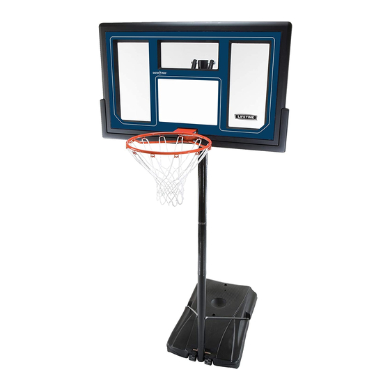
- Page 1 MODEL N° 1529 OWNER’S MANUAL...
-
Page 2: Safety Instructions
SAFETY INSTRUCTIONS FAILURE TO FOLLOW THESE WARNINGS MAY RESULT IN SERIOUS INJURY OR PROPERTY DAMAGE AND WILL VOID WARRANTY. Most injuries are caused by misuse and/or not following instructions. Use caution when using this product. BEFORE BEGINNING ASSEMBLY... - Page 3 TOOLS AND PARTS REQUIRED FOR THIS ASSEMBLY 1/2” Wrench 7/16” Wrench 9/16” Wrench 3/16” Allen Wrench 3/4” Wrench 3/8” Wrench Rubber Mallet Pliers Phillips Screwdriver Funnel Water Hose Scrap Wood Sand *Two adults required to complete assembly* Only adults should set up the product. Do not allow children in the setup area until assembly is complete.
- Page 4 ASSEMBLY GUIDES Refer to the following areas throughout the instructions to assist in the assembly process: This area is located at the top, TOOLS AND HARDWARE REQUIRED FOR THIS PAGE left-hand corner of the page and indicates which tools and hardware are needed to complete the assembly steps on a page.
-
Page 5: Parts List
PARTS LIST Item Description HARDWARE LIST Item Description Pole Assembly Hardware Pole to Base Assembly Hardware... - Page 6 HARDWARE LIST Item Description Backboard to Rim Assembly Hardware Backboard to Pole Assembly Hardware Handle Assembly Hardware...
- Page 7 PARTS IDENTIFIER Parts shown at 10% of Actual Size ” 43 ” *Warning Sticker applied to side not shown ” 3 7” 15 ” 17”...
- Page 8 PARTS IDENTIFIER Parts shown at 10% of Actual Size Parts shown at 5% of Actual Size Part shown at Actual Size...
- Page 9 PARTS IDENTIFIER Parts shown at 25% of Actual Size...
- Page 10 HARDWARE IDENTIFIER POLE ASSEMBLY HARDWARE Hardware shown at Actual Size POLE TO BASE ASSEMBLY HARDWARE Hardware shown at Actual Size BACKBOARD TO RIM ASSEMBLY HARDWARE Hardware shown at Actual Size...
- Page 11 HARDWARE IDENTIFIER BACKBOARD TO RIM ASSEMBLY HARDWARE (CONTINUED) Hardware shown at Actual Size Hardware shown at 25% of Actual Size BACKBOARD TO POLE ASSEMBLY HARDWARE Hardware shown at Actual Size 6 5/8”...
- Page 12 HARDWARE IDENTIFIER HANDLE ASSEMBLY HARDWARE Hardware shown at Actual Size 6 1/2 ” 6 5/8”...
- Page 13 POLE ASSEMBLY HARDWARE REQUIRED Hardware shown at Actual Size PARTS REQUIRED Parts shown at 10% of Actual Size Part shown at 25% of Actual Size ” 43 ” *Warning Sticker applied to side not shown ” 3 TOOLS REQUIRED 9/16” Wrench Phillips Screwdriver Scrap Wood...
- Page 14 TOOLS AND HARDWARE REQUIRED FOR THIS PAGE Top Pole (ALH) Middle Pole (ALF) 1/4” x 3/4” Screw (ADS) Domed Countersink Washer (CIH) Warning Sticker Note: The 1/4” x 3/4” Screw and Domed Countersink Washer should be fl ush with the Pole, but will spin freely once installed. Do not jam the Poles together until instructed.
- Page 15 TOOLS AND HARDWARE REQUIRED FOR THIS PAGE Scrap Wood NO HARDWARE REQUIRED FOR THIS PAGE ATTENTION: THIS STEP CANNOT BE REVERSED! Top Pole (ALH) Middle Pole (ALF) WARNING The Poles must be seated together! Even if the Poles cover the slots before seating, they must be struck on a hard surface fi...
- Page 16 TOOLS AND HARDWARE REQUIRED FOR THIS PAGE Middle Pole (ALF) Bottom Pole (ALE) 1/4” x 3/4” Screw (ADS) Domed Countersink Washer (CIH) Note: The 1/4” x 3/4” Screw and Domed Countersink Washer should be fl ush with the Pole, but will spin freely once installed. Do not jam the Poles together until instructed.
- Page 17 TOOLS AND HARDWARE REQUIRED FOR THIS PAGE 9/16” 3/8” x 3 1/2” Hex Bolts (ABH) 3/8” Flat Washers (AAF) Middle Pole (ALF) 1/2” x 2.91” Spacers (ADA) Pole Bracket (ALL) Large holes Small holes...
- Page 18 TOOLS AND HARDWARE REQUIRED FOR THIS PAGE Scrap Wood NO HARDWARE REQUIRED FOR THIS PAGE ATTENTION: THIS STEP CANNOT BE REVERSED! Top and Middle Poles (ALH and ALF) Bottom Pole (ALE) DO NOT COMPLETE ASSEMBLY WARNING The Poles must be seated together! Even if the Poles cover the slots before seating, they must be struck on a hard surface fi...
- Page 19 Bag BCQ POLE TO BASE ASSEMBLY HARDWARE REQUIRED Hardware shown at Actual Size PARTS REQUIRED Part shown at 5% of Actual Size Part shown at 25% of Actual Size Parts shown at 10% of Actual Size 7” 15 ” TOOLS REQUIRED EEO-3/16”...
- Page 20 TOOLS AND HARDWARE REQUIRED FOR THIS PAGE NO TOOLS REQUIRED FOR THIS PAGE Pole Brace (ALI) Base (AJM) Only fi nger tighten the hardware for now. Curved End Straight End Note: Repeat this step to install the other Pole Brace to the other side of the Base.
- Page 21 TOOLS AND HARDWARE REQUIRED FOR THIS PAGE 3/16" 1/2" Middle Pole (ALF) 1/2” x 15 3/4” Axle (AJC) Base (AJM) 1/2” x 7” Axle (AJE) Pole Braces (ALI) Bottom Pole (ALE) tighten all Pole to Base assembly hardware Note: Tip the system forward so the Pole rests on the ground. Do not stand the system up until it is fi...
- Page 22 BACKBOARD TO RIM ASSEMBLY HARDWARE REQUIRED Hardware shown at Actual Size Hardware shown at 25% of Actual Size...
- Page 23 BACKBOARD TO RIM ASSEMBLY PARTS REQUIRED Parts shown at 10% of Actual Size Part shown at 5% of Actual Size Part shown at 25% of Actual Size TOOLS REQUIRED 1/2” Wrench 3/8” Wrench 7/16” Wrench Pliers...
- Page 24 TOOLS AND HARDWARE REQUIRED FOR THIS PAGE 7/16” 4.86” U-Bolt (BNP) Left and Right Backboard Brackets (AJJ & AJK) Notch 1/4” x 2 3/4” Hex Bolts (AAS) 1/2” x 2 5/16” Galvanized Spacers (ABS) 1/4” Centerlock Nuts (AAB) Note: Tighten the hardware securely now.
- Page 25 TOOLS AND HARDWARE REQUIRED FOR THIS PAGE 1/2” 5/16” x 2 1/4” Tap Bolts (ABI) 5/16” Washers (ABD) 7/16” Rubber Washers (ABF) (ALX) 5/16” Hex T-Nuts (AAJ) ABD ABF Note: Make sure that the 5/16” x 2 1/4” Tap Bolts are positioned on the outside edge of the holes as shown.
- Page 26 TOOLS AND HARDWARE REQUIRED FOR THIS PAGE 1/2” Rim Support Channel (AOX) Backboard (AJI) 4.86” U-Bolt (BNP) Rim (ALX) Backboard (AJI) 5/16” Jam Nuts (AAV) 4.86” U-Bolt (BNP) 5/16” Nylock Flange Nuts (ABK) 5/16” x 2 1/4” Tap Bolts (ABI)
- Page 27 TOOLS AND HARDWARE REQUIRED FOR THIS PAGE 1/2” Compression Springs (AJW) 4.86” U-Bolt (BNP) Spring Retainer Plate (AOW) 5/16” Nylock Flange Nuts (ABK) Rim (ALX) Note: DO NOT COMPLETELY TIGHTEN THE 5/16” NYLOCK FLANGE NUTS IN THIS STEP! Only tighten the Nuts until the Rim does not wobble. Tightening the Nuts will adjust the Rim tension.
- Page 28 TOOLS AND HARDWARE REQUIRED FOR THIS PAGE 3/8” Left and Right Backboard Brackets (AJJ & AJK) Backboard (AJI)
- Page 29 BACKBOARD TO POLE ASSEMBLY HARDWARE REQUIRED Hardware shown at Actual Size 6 5/8” PARTS REQUIRED Parts shown at 10% of Actual Size 17” Part shown at 25% of Actual Size TOOLS REQUIRED 3/4” Wrench 7/16” Wrench Rubber Mallet...
- Page 30 TOOLS AND HARDWARE REQUIRED FOR THIS PAGE 7/16” NO HARDWARE REQUIRED FOR THIS PAGE Counterbalance Spring (AJY) 1/2” x 2 5/16” Galvanized Spacer (ABS) Note: It may be necessary to use a Rubber Mallet to snap the Counterbalance Spring into place.
- Page 31 TOOLS AND HARDWARE REQUIRED FOR THIS PAGE 6 5/8” 3/4” Short Extension Arms (AKC) Note: Tighten the 1/2” Centerlock Nut (AAX) until it is fl ush with the end of the Bolt.
- Page 32 TOOLS AND HARDWARE REQUIRED FOR THIS PAGE 6 5/8” 3/4” Long Extension Arms (AKB) Note: Tighten the 1/2” Centerlock Nut (AAX) until it is fl ush with the end of the Bolt.
- Page 33 TOOLS AND HARDWARE REQUIRED FOR THIS PAGE 6 5/8” 3/4” CAUTION: HAVE ONE ADULT HOLD THE BACKBOARD IN PLACE UNTIL ASSEMBLY HAS BEEN COMPLETED! Short and Long Extension Arms (AKC & AKB) Note: Tighten the 1/2” Centerlock Nut (AAX) until it is fl ush with the end of the Bolt.
- Page 34 HANDLE ASSEMBLY HARDWARE REQUIRED Hardware shown at Actual Size 6 1/2 ” 6 5/8”...
- Page 35 HANDLE ASSEMBLY PARTS REQUIRED Parts shown at 10% of Actual Size Parts shown at 25% of Actual Size Parts shown at Actual Size TOOLS REQUIRED 7/16” Wrench 1/2” Wrench Phillips Screwdriver 3/4” Wrench 9/16” Wrench...
- Page 36 TOOLS AND HARDWARE REQUIRED FOR THIS PAGE Lock Tab (AQG) Trigger (AMN) Note: Make sure the Lock Tab is oriented as shown when attaching the Tab to the Trigger. Right Handle (AKN) Outer Tube (ALB) Note: Make sure that the Inner Channel (AKQ) has been removed from the Outer Tube before performing this step.
- Page 37 TOOLS AND HARDWARE REQUIRED FOR THIS PAGE Trigger Spring (AQH) Trigger (AMN) Right Handle (AKN) Lock Tab (AQG) Outer Tube (ALB) Note: Pull the Trigger to ensure it moves correctly before attaching the Left Handle (AKL). Left Handle (AKL) Right Handle (AKN) Outer Tube (ALB) Note: To prevent stripping the holes in the Handles, do not overtighten the #6 x 5/8”...
- Page 38 TOOLS AND HARDWARE REQUIRED FOR THIS PAGE 7/16” 1/4” x 1 1/4” Hex Bolt (AAL) Outer Tube (ALB) 1/4” Cap Nut (ADJ) WARNING...
- Page 39 TOOLS AND HARDWARE REQUIRED FOR THIS PAGE 1/2” Trigger (AMN) Inner Channel (AKQ) Outer Tube (ALB) Note: Ensure that the notches on the Inner Channel face the Handle as shown. Inner Channel (AKQ) Pole Bracket (ALL) WARNING...
- Page 40 TOOLS AND HARDWARE REQUIRED FOR THIS PAGE 6 5/8” 3/4” Outer Tube (ALB) Long Extension Arms (AKB) Note: Tighten the 1/2” Centerlock Nut (AAX) until it is fl ush with the end of the Bolt.
- Page 41 TOOLS AND HARDWARE REQUIRED FOR THIS PAGE 6 1/2 ” 9/16” 3/8” x 6 1/2” Hex Bolt (ABA) Short Extension Arms (AKC) 3/8” Centerlock Nut (ABB) Note: Tighten the 3/8” Centerlock Nut until it is fl ush with the end of the Bolt.
- Page 42 TOOLS AND HARDWARE REQUIRED FOR THIS PAGE Wrench NO HARDWARE REQUIRED FOR THIS PAGE 5.10 Counterbalance Spring (AJY) 3/8” x 6 1/2” Hex Bolt (ABA) Note: Make sure all hardware has been securely tightened before moving to the next section.
- Page 43 FINAL ASSEMBLY HARDWARE REQUIRED NO HARDWARE REQUIRED FOR THIS SECTION PARTS REQUIRED Parts shown at 10% of Actual Size Parts shown at Actual Size TOOLS REQUIRED Sand Water Hose Funnel...
- Page 44 TOOLS AND HARDWARE REQUIRED FOR THIS PAGE NO HARDWARE REQUIRED FOR THIS PAGE Two adults are required to complete assembly. To prevent serious injuries, the Pole should be held down by one adult at all times while the Base is being fi lled. OPTION A: FILLING WITH SAND Base Plug (AEF) Base (AJM)
- Page 45 TOOLS AND HARDWARE REQUIRED FOR THIS PAGE NO HARDWARE REQUIRED FOR THIS PAGE Two adults are required to complete assembly. To prevent serious injuries, the Pole should be held down by one adult at all times while the Base is being fi lled. OPTION B: FILLING WITH WATER Base Plug (AEF) Base (AJM)
- Page 46 TOOLS AND HARDWARE REQUIRED FOR THIS PAGE NO TOOLS OR HARDWARE REQUIRED FOR THIS PAGE Net (AKZ) Rim (ALX) Note: If a replacement Net is needed, please call our Customer Service Department. Our Nets are shorter than average to reduce the risk of entanglement. Height Sticker (AKP) Left Handle (AKL)
- Page 47 OPERATION OF HEIGHT ADJUSTMENT SYSTEM ONLY ADULTS SHOULD ADJUST THE HEIGHT OF THE SYSTEM. MOVING THE SYSTEM WARNING: CAUTION: POLE CARE AND SYSTEM MAINTENANCE IF RUST HAS PENETRATED THROUGH THE POLE ANYWHERE, REPLACE IT IMMEDIATELY!
- Page 48 WARNING FAILURE TO FOLLOW THESE WARNINGS MAY RESULT IN SERIOUS INJURY AND/OR PROPERTY DAMAGE.
-
Page 49: Warranty Information
WARRANTY INFORMATION LIFETIME BASKETBALL EQUIPMENT 5-YEAR LIMITED FACTORY WARRANTY THE MANUFACTURER RESERVES THE RIGHT TO MAKE SUBSTITUTIONS TO WARRANTY CLAIMS IF PARTS ARE UNAVAILABLE OR OBSOLETE. Discover other sports equipment on our website.
Need help?
Do you have a question about the 1529 and is the answer not in the manual?
Questions and answers