
Related Manuals for Lifetime 51544


Summary of Contents for Lifetime 51544
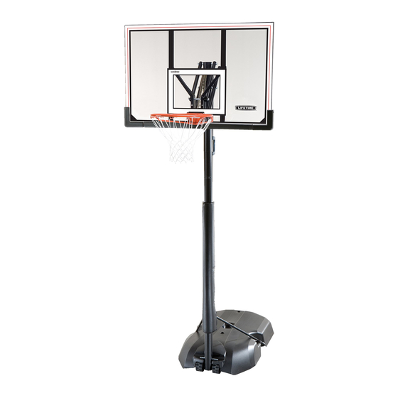
- Page 1 MODEL N° 51544 OWNER’S MANUAL Keep this Product ID Number and use when contacting Customer Service:...
- Page 2 Maintaining your privacy is our long-standing policy at Lifetime. And you can rest as- sured that Lifetime will not sell or provide your personal data to other third parties, or allow them to use your personal data for their own purposes.
-
Page 3: Safety Instructions
SAFETY INSTRUCTIONS To ensure safety, do not attempt to assemble this product without reading and following all instructions carefully. Check the entire box and inside all packing materials for parts and/or additional instruction material. Before beginning assembly, identify and inventory all parts and hardware using the parts and hardware lists and identifi... - Page 4 TOOLS AND PARTS REQUIRED FOR THIS ASSEMBLY Electric Drill Pliers Rubber Mallet Phillips Screwdriver Sand (362 lb) *Two adults required to complete assembly*...
- Page 5 ASSEMBLY GUIDES Refer to the following areas throughout the instructions to assist in the assembly process: This area is located at the top, TOOLS AND HARDWARE REQUIRED FOR THIS PAGE left-hand corner of the page and indicates which tools and hardware are needed to on a page.
-
Page 6: Table Of Contents
PARTS LIST Item Description Top Pole Middle Pole Bottom Pole Right Backboard Bracket Backboard Counterbalance Spring Short Extension Arm Outer Tube Inner Channel Trigger Right Handle Pole Bracket Plastic Guard Base Pole Brace Wheel 1/2” x 15 3/4” Axle 1/2” x 7” Axle Base Plug Pole Pad Corner Frame Pad... -
Page 7: Hardware List
HARDWARE LIST Item Description Pole to Base Assembly Hardware (1066284) Continued 1/4” Barrel Nut 1/4” x 3” Shoulder Bolt 3/16” Allen Wrench Backboard to Rim Assembly Hardware (1045426) 1/4” x 2 3/4” Hex Bolt 1/2” x 2 5/16” Galvanized Spacer 5/16”... -
Page 8: Top Pole
PARTS IDENTIFIER Parts shown at 10% of Actual Size ” ALH (x1) Top Pole 43 ” (x1) Middle Pole 43 ” ALE (x1) Bottom Pole 40” ALB (x1) Outer Tube ” 7” AKQ (x1) Inner Channel (x1) 1/2” x 7” Axle ALI (x2) Pole Brace 15 ”... - Page 9 PARTS IDENTIFIER Parts shown at 10% of Actual Size ALX (x1) AKZ (x1) (x2) Corner Frame Pad (x1) Center Frame Pad Parts shown at 5% of Actual Size (x1) Base (x1) ALN (x1) Backboard Pole Pad...
-
Page 10: Pole Bracket
PARTS IDENTIFIER Parts shown at 25% of Actual Size AKL (x1) AKN (x1) Right Handle AMU (x2) Wheel (x1) ALD (x1) Counterbalance Spring Plastic Guard AMN (x1) ALL (x1) Trigger Pole Bracket Part shown at Actual Size (x2) Base Plug... -
Page 11: Allen Wrench
HARDWARE IDENTIFIER Hardware shown at Actual Size ABH (x2) (x2) 3/8” x 3 1/2” Hex Bolt 3/8” Washer ADA (x2) 1/2” x 2.91” Spacer ABB (x2) 3/8” Centerlock Nut CIH (x2) ADS (x2) Domed Countersink Washer 1/4” x 3/4” Screw Hardware shown at Actual Size ABD (x4) ABN (x2) - Page 12 HARDWARE IDENTIFIER Hardware shown at Actual Size ACS (x2) .38” x 1” Steel ABS (x2) Spacer 1/2” x 2 5/16” Galvanized Spacer AAV (x2) 5/16”Jam Nut AAB (x2) (x2) 1/4” Centerlock Nut 5/16” x 2 1/2” Tap Bolt (x2) (x2) ABK (x6) ABD (x2) 7/16”...
-
Page 13: Centerlock Nut
HARDWARE IDENTIFIER Hardware shown at Actual Size AAU (x1) AAN (x1) AAL (x1) 1/4” Cap Nut 5/16” Cap Nut 1/4” x 1 1/4” Hex Bolt AAM (x1) (x1) ACZ (x2) 5/16” x 1 1/2” Tap Bolt .69” x 1.4” Spacer 6 1/2”... - Page 14 POLE ASSEMBLY HARDWARE REQUIRED Hardware shown at Actual Size ABH (x2) (x2) 3/8” x 3 1/2” Hex Bolt 3/8” Washer ADA (x2) 1/2” x 2.91” Spacer ABB (x2) CIH (x2) 3/8” Centerlock Domed Countersink Washer ADS (x2) 1/4” x 3/4” Screw PARTS REQUIRED Parts shown at 10% of Actual Size Part shown at 25% of Actual Size...
- Page 15 TOOLS AND HARDWARE REQUIRED FOR THIS PAGE ADS (x1) CIH (x1) Align the hole in the Top Pole (ALH) with the slot in the slide the Top Pole over the Middle Pole. Insert a 1/4” x 3/4” Screw (ADS) through a and into the small hole in the Top Pole and into the slot in the Middle Pole as shown.
- Page 16 TOOLS AND HARDWARE REQUIRED FOR THIS PAGE ADS (x1) CIH (x1) Align the hole in the with the slot in the Bottom Pole (ALE) and slide the Middle Pole over the Bottom Pole. Insert a 1/4” x 3/4” Screw (ADS) through a and into the small hole in the Middle Pole and into the slot in the Bottom Pole as shown.
- Page 17 TOOLS AND HARDWARE REQUIRED FOR THIS PAGE ADA (x2) 9/16” (x2) ABB (x2) ABH (x2) (x2) Insert the 3/8” x 3 1/2” Hex Bolts (ABH) with the into as shown. Then slide the 1/2” x 2.91” Spacers (ADA) onto the Hex Bolts. Place the onto the 3/8”...
- Page 18 TOOLS AND HARDWARE REQUIRED FOR THIS PAGE ATTENTION: THIS STEP CANNOT BE REVERSED! In order to seat the Poles, strike each end of the Pole very hard fi ve to six times on a piece of scrap wood or cardboard. This must be done even if the Poles cover the slots before seating has occurred.
- Page 19 POLE TO BASE ASSEMBLY HARDWARE REQUIRED Hardware shown at Actual Size BTS (x1) ABD (x4) AAE (x2) ABN (x2) 1/4” Barrel Nut 5/16” Washer 5/16” x 1” Hex Bolt 1/2” x 1/8” Spacer BZO (x1) AAO (x2) 1/4” x 3” Shoulder Screw 5/16”...
- Page 20 TOOLS AND HARDWARE REQUIRED FOR THIS PAGE AAE (x2) ABD (x4) ABN (x2) AAO (x2) Attach the fl attened end of the Pole Brace (ALI) to the with the hardware shown. Remove any residual plastic in the hole with pliers. Only fi nger tighten the hardware. Note: Repeat this step to install the other Pole Brace to the other side of the Base.
- Page 21 TOOLS AND HARDWARE REQUIRED FOR THIS PAGE 1/2" (x2) BZO (x1) 3/16" (x2) BTS (x1) Place the Pole assembly on the ground with the facing down. Position the under the bottom slots of the as shown, and step onto the Base so the Axle snaps into the slots.
- Page 22 BACKBOARD TO RIM ASSEMBLY HARDWARE REQUIRED Hardware shown at Actual Size AAS (x2) ABC (x2) 1/4” x 2 3/4” Hex Bolt 5/16” x 1 1/4” Carriage Bolt ACS (x2) AAB (x2) .38” x 1” Steel Spacer 1/4” Centerlock Nut ABD (x2) (x2) 5/16”...
- Page 23 BACKBOARD TO RIM ASSEMBLY PARTS REQUIRED Parts shown at 10% of Actual Size ALX (x1) (x1) (x1) Right Backboard Bracket Part shown at 5% of Actual Size Part shown at 25% of Actual Size ALD (x1) Plastic Guard (x1) Backboard TOOLS REQUIRED (x2) Pliers...
- Page 24 TOOLS AND HARDWARE REQUIRED FOR THIS PAGE 7/16” (x2) AAS (x2) AOU (x1) ABS (x2) AAB (x2) (Not to scale) Slide the 4 1/2” U-Bolt (AOU) through the as shown. Notch Connect the Backboard Brackets together using two 1/4” x 2 3/4” Hex Bolts (AAS), two , and two 1/4”...
- Page 25 TOOLS AND HARDWARE REQUIRED FOR THIS PAGE 1/2” (x2) (x2) ABD (x2) (x2) Insert two with the and the through the bottom holes in the back of the Rim (ALX) as shown, and secure the hardware with two Note: Make sure that the 5/16” x 2 1/2” Tap Bolts are positioned on the outside edge of the holes as shown.
- Page 26 TOOLS AND HARDWARE REQUIRED FOR THIS PAGE 1/2” ACS (x2) AAV (x2) ABK (x2) Insert the 4 1/2” U-Bolt (AOU) through the upper part of the opening on the backside of the as shown. Connect the Rim (ALX) and to the with the hardware shown.
- Page 27 TOOLS AND HARDWARE REQUIRED FOR THIS PAGE (x1) (x2) 1/2” (Not to scale) (Not to scale) ABK (x2) Slide the onto the 4 1/2” U-Bolt (AOU), and place the over the Compression Springs. Tighten the until the Rim (ALX) does not wobble to complete this step.
- Page 28 TOOLS AND HARDWARE REQUIRED FOR THIS PAGE 1/2” ABC (x2) ABK (x2) Slide a 5/16” x 1 1/4” Carriage Bolt (ABC) into the crimped slot in each Backboard Channel as shown. Bend the Backboard Brackets outward by hand and gently lift them over the 5/16”...
- Page 29 BACKBOARD TO POLE ASSEMBLY HARDWARE REQUIRED Hardware shown at Actual Size ABL (x4) ABP (x4) AAX (x4) 1/2” x 3/8” Clear .69” x .59” Black 1/2” Centerlock Nut Spacer Poly Spacer 6 5/8” (Not actual length) (x4) 1/2” x 6 5/8” Hex Bolt PARTS REQUIRED Parts shown at 10% of Actual Size 26”...
- Page 30 TOOLS AND HARDWARE REQUIRED FOR THIS PAGE 7/16” (x2) Place one end of the over the lower as shown. Note: It may be necessary to use a Rubber Mallet to snap the Counterbalance Spring into place. If the Rubber Mallet does not work , undo the hardware in the image that has been shaded gray.
- Page 31 TOOLS AND HARDWARE REQUIRED FOR THIS PAGE 6 5/8” 3/4” (x2) (x1) (Not actual length) AAX (x1) ABL (x2) Secure the Short Extension Arms (AKC) to the Backboard Brackets in the location shown with the hardware indicated. Note: Tighten the 1/2” Centerlock Nut (AAX) until it is fl ush with the end of the Bolt.
- Page 32 TOOLS AND HARDWARE REQUIRED FOR THIS PAGE 6 5/8” (x1) 3/4” (x2) (Not actual length) AAX (x1) ABL (x2) Secure the Long Extension Arms (AKB) to the Backboard Brackets in the location shown with the hardware indicated. Note: Tighten the 1/2” Centerlock Nut (AAX) until it is fl ush with the end of the Bolt.
- Page 33 TOOLS AND HARDWARE REQUIRED FOR THIS PAGE 6 5/8” (x2) 3/4” (x2) (Not actual length) AAX (x2) ABP (x4) CAUTION: HAVE ONE ADULT HOLD THE BACKBOARD IN PLACE UNTIL ASSEMBLY HAS BEEN COMPLETED! Pole assembly. Rest the Rim on cardboard to prevent scratching. Then secure the Short and Long Extension Arms (AKC &...
- Page 34 HANDLE ASSEMBLY HARDWARE REQUIRED Hardware shown at Actual Size AAU (x1) AAL (x1) AAN (x1) 1/4” Cap Nut 1/4” x 1 1/4” Hex Bolt 5/16” Cap Nut AAM (x1) 5/16” x 1 1/2” Tap Bolt ACZ (x2) (x1) .69” x 1.4” Spacer 6 1/2”...
- Page 35 HANDLE ASSEMBLY PARTS REQUIRED Parts shown at 10% of Actual Size 40” ALB (x1) Outer Tube ” AKQ (x1) Inner Channel Parts shown at 25% of Actual Size AKL (x1) AKN (x1) Right Handle AMN (x1) Trigger TOOLS REQUIRED (x2) Phillips Screwdriver (x2) (x2)
- Page 36 TOOLS AND HARDWARE REQUIRED FOR THIS PAGE AAP (x2) (x1) Secure the to the Trigger (AMN) with the hardware shown. Note: Make sure the Lock Tab is oriented as shown when attaching the Tab to the Trigger. Place the Right Handle (AKN) onto the Outer Tube (ALB) so that the notch of the Outer Tube fi...
- Page 37 TOOLS AND HARDWARE REQUIRED FOR THIS PAGE ADT (x7) AQH (x1) Place the Trigger Spring (AQH) onto the Trigger (AMN) as shown. Then place the Trigger inside the Right Handle (AKN) so that the fi ts into the slot on the Outer Tube (ALB) as shown. Note: Pull the Trigger to ensure it moves correctly before attaching the Left Handle (AKL).
- Page 38 TOOLS AND HARDWARE REQUIRED FOR THIS PAGE 7/16” (x2) AAL (x1) AAU (x1) Insert the 1/4” x 1 1/4” Hex Bolt (AAL) through the holes indicated on the Outer Tube (ALB). Secure the 1/4” x 1 1/4” Hex Bolt to the Outer Tube with the 1/4” Cap Nut (AAU). Do not overtighten the Cap Nut.
- Page 39 TOOLS AND HARDWARE REQUIRED FOR THIS PAGE 1/2” (x2) AAM (x1) AAN (x1) While holding the Trigger (AMN) in, insert the notched end of the Inner Channel (AKQ) into the Outer Tube (ALB). Continue to insert the Inner Channel into the Outer Tube until the Trigger clicks into the fi rst slot. Then release the Trigger.
- Page 40 TOOLS AND HARDWARE REQUIRED FOR THIS PAGE 6 5/8” (x1) 3/4” (x2) (Not actual length) AAX (x1) ACZ (x2) Secure the Outer Tube (ALB) to the Long Extension Arms (AKB) with the hardware shown. Note: Tighten the 1/2” Centerlock Nut (AAX) until it is fl ush with the end of the Bolt.
- Page 41 TOOLS AND HARDWARE REQUIRED FOR THIS PAGE 6 1/2” 9/16” (x2) (Not actual length) ABA (x1) ABB (x1) Insert the 3/8” x 6 1/2” Hex Bolt (ABA) through the holes in the Short Extension Arms (AKC) that are closest to the Pole. Secure the 3/8” x 6 1/2” Hex Bolt to the Short Extension Arms with the Note: Tighten the 3/8”...
- Page 42 TOOLS AND HARDWARE REQUIRED FOR THIS PAGE TOOLS AND HARDWARE REQUIRED FOR THIS PAGE Using the closed end of a Wrench, stretch the 5.10 up and over the 3/8” x 6 1/2” Hex Bolt (ABA) as shown. Note: Make sure all hardware has been securely tightened before moving to the next section.
- Page 43 HARDWARE REQUIRED Hardware shown at Actual Size ADP (x10) PARTS REQUIRED Part shown at 10% of Actual Size (x2) AKZ (x1) Corner Frame Guard (x1) Center Frame Guard Part shown at Actual Size Part shown at 5% of Actual Size (x2) Base Plug ALN (x1)
- Page 44 TOOLS AND HARDWARE REQUIRED FOR THIS PAGE ADP (x8) Remove the plastic fi lm from the , and attach the to the Backboard in the location shown with the hardware indicated. Make sure that the Center Frame Pad is centered on the metal piece of the Backboard as shown. Attach the to the in the locations...
- Page 45 TOOLS AND HARDWARE REQUIRED FOR THIS PAGE (362 lb) (362 lb of sand required) a. Insert a into the in the hole closest to the Pole. b. Using a funnel, fi ll the Base with sand through the hole furthest from the Pole until the sand is just below the hole.
- Page 46 TOOLS AND HARDWARE REQUIRED FOR THIS PAGE a. Insert a into the in the hole closest to the Pole. b. Fill the Base with cold water through the hole furthest from the Pole until the water is just below the hole. c.
- Page 47 TOOLS AND HARDWARE REQUIRED FOR THIS PAGE Attach Net (AKZ) to the Rim (ALX). Note: If a replacement Net is needed, please call our Customer Service Department. Our Nets are shorter than average to reduce the risk of entanglement. Pull the Handle all the way down so the system is at the highest setting. with the arrow on the Left Handle (AKL), and apply the Sticker to the back of the Pole as shown.
- Page 48 TOOLS AND HARDWARE REQUIRED FOR THIS PAGE Attach Pole Pad (ALN) to the Pole.
- Page 49 OPERATION OF HEIGHT ADJUSTMENT SYSTEM The basketball system may be adjusted from 8 feet to 10 feet. the Backboard. Raising the Handle will lower the Backboard. MOVING THE SYSTEM The system must only be moved by people capable of handling its weight. Children should not be allowed to move the system. a.
- Page 50 ® ENHANCE YOUR LIFETIME PURCHASE BY ADDING ACCESSORIES OR OTHER GREAT PRODUCTS: To purchase accessories or other Lifetime Products, visit us at: www.lifetime.com Or call: 1-800-424-3865...
- Page 51 No cuelgue nada de la dañar el sistema y anular la garantía. www.lifetime.com #FS16400 10/12/2004...
-
Page 52: Warranty Information
This warranty gives you specifi c legal rights, and you may also have other rights which vary from state to state. **Call or visit our Web site for Saturday hours** Please include your dated sales receipt and photographs of damaged parts. www.lifetime.com...
Need help?
Do you have a question about the 51544 and is the answer not in the manual?
Questions and answers