Advertisement
Installation Instructions for
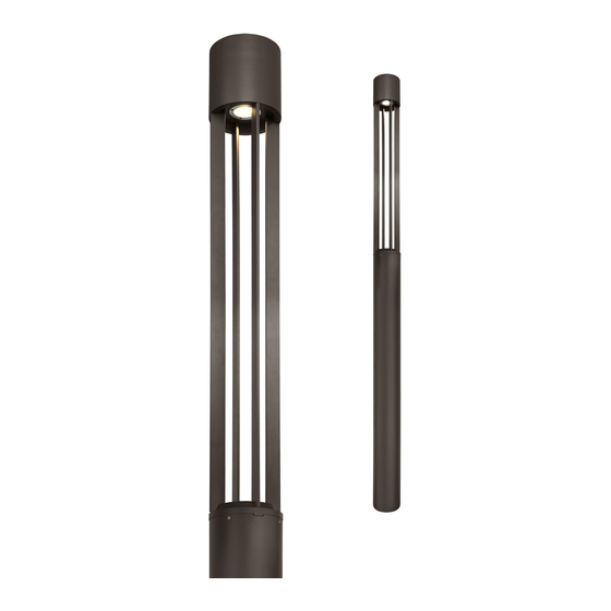
Turbo Column
G
ENERAL RODUCT NFORMATION
P
I
This product is suitable for wet locations.
Refer to the product specsheet for dimming information.
Install the Column
1A
ALLEN
WRENCH
SET SCREW
Loosen
(Do Not Remove)
1
column base with the provided Allen wrench and
remove the base plate.
1B
3
Bring the power wires to the fixture location in
2
accordance with local electrical codes.
Mount the base plate to an even and smooth surface
3
using the provided template on page 3.
NOTE: anchor/lag bolts, nuts, and washers not
provided.
OUTDOOR
:
1
BASE PLATE
the four set screws on
2
3
CAUTION RISK OF FIRE
This product must be installed in accordance with
the applicable installation code by a person familiar
with the construction and operation of the product
and the hazards involved.
Use minimum 90°c supply conductors.
1C
COLUMN TOP TAB
4
COLUMN BOTTOM SLOT
Align the tab on the column top to the slot in the
4
column base, insert the fixture wires into the column
base, and assemble them together.
5
Secure them together by installing the Allen bolts and
washers with the provided Allen wrench.
1D
Carefully install the column assembly onto the base
6
plate and secure it in place by tightening all 4 set
screws.
1
920OCTURBO
700OCTUR_
-
ALLEN BOLT
& WASHERS
ALLEN WRENCH
5
ALLEN
WRENCH
SET SCREW
1.5
1.0
Advertisement
Table of Contents

Related Manuals for Tech Lighting 700OCTUR

Summary of Contents for Tech Lighting 700OCTUR
- Page 1 Installation Instructions for 920OCTURBO Turbo Column 700OCTUR_ OUTDOOR ENERAL RODUCT NFORMATION This product is suitable for wet locations. Refer to the product specsheet for dimming information. CAUTION RISK OF FIRE This product must be installed in accordance with the applicable installation code by a person familiar with the construction and operation of the product and the hazards involved.
- Page 2 Wire the Column Loosen (Do Not Remove) the access panel set screw on column base with the provided Allen wrench. Pull away the top of the access panel and lift it completely out the column base. Connect the red and black wires from the column top Power the fixture using the following steps or wiring respectively to the red and black wires in the column diagrams according to the options included with the...
- Page 3 Use the gray and purple dimming wires for 0-10v dimming application (if not in use, make sure to cap these wires off). Reinstall the access panel (reversal of section 2A). Note for Photocell equipped fixtures: at initial power up, the photocell must calibrate which will cause the fixture to cycle on/off for a moment.
- Page 4 SAVE THESE INSTRUCTIONS! 847.410.4400 www.techlighting.com © 2018 Tech Lighting, L.L.C. All rights reserved. The "Tech Lighting" graphic is a registered trademark of Tech Lighting, L.L.C. Tech Lighting reserves the right to change specifications for product improvements without notification. A Generation Brands Company...
Need help?
Do you have a question about the 700OCTUR and is the answer not in the manual?
Questions and answers