CTC Union EcoHeat 400 Installation And Maintenance Manual
400v 3n~ / 230v 1n~
Hide thumbs
Also See for EcoHeat 400:
- Installation and maintenance manual (68 pages) ,
- Installation and maintenance manual (116 pages)

Subscribe to Our Youtube Channel
Related Manuals for CTC Union EcoHeat 400


Summary of Contents for CTC Union EcoHeat 400
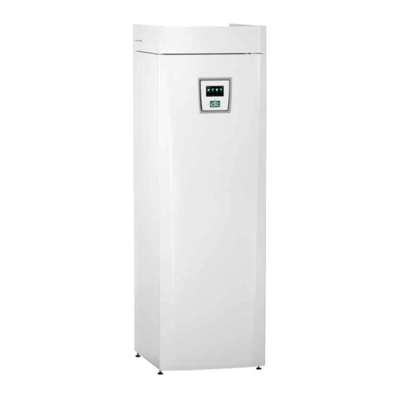
- Page 1 162 205 02-3 2018-01-23 Providing sustainable energy solutions worldwide Installation and Maintenance Manual CTC EcoHeat 400 400V 3N~ / 230V 1N~ IMPORTANT READ CAREFULLY BEFORE USE KEEP FOR FUTURE REFERENCE...
- Page 2 Removing the cooling module 1. Disconnect the cooling module’s power cable con- 2. Attach the two carrying handles to the bottom of the nector and hoses. cooling module. 3. Unscrew the cooling module’s screws. 4. Pull the cooling module by i rst lifting the front edge slightly with the carrying handles.
- Page 3 Installation and maintenance manual 162 205 02-3 2018-01-23 CTC EcoHeat 400 400 V 3N~ / 230 V 1N~...
-
Page 4: Table Of Contents
Technical Data Unpacking _____________________________________________________ _______________________________________________________ Single phase 230V 1N~ Recycling ____________________________________ ________________________________________________________ Measurements and connections Standard delivery ________________________ _____________________________________________ CTC EcoHeat 400 design Pipe installation ___________________________________ ___________________________________________________ Parameter list Filling ______________________________________________________ ______________________________________________________________ Menu overview Schematic diagram ____________________________________________________ __________________________________________ Detail Description Menus 10. - Page 5 If it is looked after properly, you • Facilitates the setting of values and troubleshooting in will be able to enjoy the use of your CTC EcoHeat 400 for a simple and well-structured way many years. This manual will provide all the information you The built-in copper coil provides copious amounts of will need.
-
Page 6: Check List
Check and filling, heating system † Fine tuning information, heat curve † Alarm information † Mixing valve † Safety valve function test † Warranty † Information on procedures for fault registration † _____________________________________ ______________________________________ Date / Customer Date / Installer CTC EcoHeat 400... -
Page 7: Important To Remember
• Remember to leave a service area of at least 1 m in front of the product. • The product must not be placed below floor level either. • Avoid placing EcoHeat in rooms with lightly insulated walls where neighbouring rooms may be disturbed by the compressor and vibrations. CTC EcoHeat 400... -
Page 8: Safety Instructions
Enertech’s commitment under the applicable warranty terms is not binding. Information in this type of box [i] is intended to help ensure that the product functions optimally. Information in this type of box [!] is particularly important for correctly installing and using the product. CTC EcoHeat 400... -
Page 9: Your Home's Heating Installation
Installer/Settings/Radiator system menu. Recommended values are: Floor heating only Inclination 35 Low temperature system (well insulated houses) Inclination 40 Normal temperature system (factory setting) Inclination 50 High temperature system (older houses, small radiators, poorly insulated) Inclination 60 CTC EcoHeat 400... - Page 10 You then need to adjust the heating curve, as necessary, following the method shown above. When the basic values have been set more or less correctly, the curve can be finely adjusted directly using the Room temp. shown on the home menu screen. CTC EcoHeat 400...
- Page 11 Inclination 60 °C Adjustment 0 °C In this example, the maximum outgoing primary flow temperature is set at 55 °C. The minimum permitted primary flow temperature is 27 °C (e.g. summer-time basement heating or the floor circuits in a bathroom). Outside Temperature CTC EcoHeat 400...
- Page 12 Off means that the heating is switched off. For systems with a radiator pump, the radiator pump is switched off. - No selection means no function when activated. CTC EcoHeat 400...
-
Page 13: Technical Data
Heating system. nominal flow Pressure drop for mixing valve heating See pressure drop diagram in the Pipe installation chapter ∆t = 10 K and 0/35 °C heat pump operation No annual leakage control of the refrigerant is required CTC EcoHeat 400... - Page 14 3.1 (31 bar) Weight Depth x Width x Height 672 x 595 x 1904 Minimum ceiling height 1925 Sound power according to EN12102 dB(A) 44.9 43.9 48.5 48.0 No annual leakage control of the refrigerant is required CTC EcoHeat 400...
-
Page 15: Single Phase 230V 1N
Heating system. nominal flow Pressure drop for mixing valve heating See pressure drop diagram in the Pipe installation chapter ∆t = 10 K and 0/35 °C heat pump operation No annual leakage control of the refrigerant is required CTC EcoHeat 400... - Page 16 3.1 (31 bar) Weight Depth x Width x Height 642 x 600 x 1850 Minimum ceiling height 1925 Sound power according to EN12102 dB(A) 44.9 43.9 48.5 48.0 No annual leakage control of the refrigerant is required CTC EcoHeat 400...
-
Page 17: Measurements And Connections
5. Radiator primary fl ow 22 compression 6. Radiator return/expansion Ø22 7. From ground loop Ø28 (right, left and back) 8. To ground loop Ø28 (right, left and back) 9. Lifting sleeve 3/4 " 10. Connection for external systems (pipe penetration) 87 134 CTC EcoHeat 400... -
Page 18: Ctc Ecoheat 400 Design
2. CTC EcoHeat 400 design The picture below shows the fundamental construction of the heat pump. The energy in the lake or ground is drawn up by the cooling system. The compressor then increases the temperature to a usable level. Afterwards it releases the energy for the heating system and hot water. -
Page 19: Parameter List
Smart block mixing valve Conv. factor curr. sensors Input voltage 3x400 V Tariff EL Upper tank Factory User (set) value value Stop temp HP ºC Start/stop diff ºC Max. time upper tank Max. time lower tank Time lower after DHW CTC EcoHeat 400... -
Page 20: Menu Overview
4. Menu overview Night reduction heat circ. Start menu CTC EcoHeat 400 Monday 09:35 Weekly program Day by day 00 - 06 22 - 24 Monday Tuesday 00 - 06 22 - 24 Wednesday 00 - 06 22 - 24... - Page 21 Remote control Service Function test Heating circuit Function test Heat pump Alarm log Valves Electric heater Factory settings coded Solar Quick start compressor. Diff thermostat function Software update, USB Pool Write log to USB Control current sensors Re-installation CTC EcoHeat 400...
-
Page 22: Detail Description Menus
5. Detail Description Menus Start menu All the settings can be configured directly on screen using CTC EcoHeat 400 Monday 09:35 the well-structured control panel. The large icons operate as buttons on the touch display. Start menu This menu is the system's start menu. This provides an Room temp. -
Page 23: Room Temp
The systems. Radiator system 1 with a room sensor and radiator product's alarm is triggered. system 2 without one. The radiator thermostatic valves must be held fully open when the system is tuned. CTC EcoHeat 400... -
Page 24: Night Reduction Temperature
Temporary extra hot water and the weekly program for extra hot water are stopped. The heat pump only operates in the lower tank. The value by which the temperature is reduced - Room temp. red – is set under Installer/Settings/Radiator system/ Factory value: -2 °C. CTC EcoHeat 400... -
Page 25: Dhw
This is used if you always know when you repeatedly need extra hot water, for instance, during the Tip: Set the time approx. 1 hour earlier morning and evening. than you need the hot water as it take some time to heat up the water. CTC EcoHeat 400... -
Page 26: Operation
This value operation). If two radiator systems will vary during operation according to the parameters set, are installed, the values for both are the radiator system's capacity and the current outdoor displayed. temperature. CTC EcoHeat 400... -
Page 27: Operation Data Ecoheat
Indicates whether the charge pump (G46) from the external tank is turned on (ON, OFF) Indicates the temperature in the external tank.(B46) Pool ºC Off 19 (22) Pool function Shows whether pumps (G50,G51) are switched on (ON, OFF). Displays pool temperature and (setpoint). CTC EcoHeat 400... -
Page 28: Stored Operation Data
Current L1 percentage. Brine pump (On — .Off) Shows whether the brine pump is operating or not. HP in/out °C Shows the heat pump's return and primary flow temperatures. Current L1 Shows the current across the compressor (phase L1). CTC EcoHeat 400... -
Page 29: Operation Data Heating
The blue curve is the current outdoor temperature. Room1 Prim1 Return Room2 Prim2 Green/pink curves are room temperatures 1 and 2. Red/grey curves are primary flow temperatures 1 and 2. The yellow curve is the heat pump's return temperature. CTC EcoHeat 400... -
Page 30: Installer
Settings, Define system and Service. Time/Language Settings Define system Service Time/Language includes time and language settings for your CTC EcoHeat 400. Software display PCB: 20120205 Settings are used both by the installer and users for Software HP PCB: 20120125 installing the system. -
Page 31: Settings
There is no heating, the radiator pump does not run (is turned over). Heating mode, ext Switching between heating and summer mode can be controlled remotely. Specify here what is to happen with remote control. Find out more in the section entitled “Define/Remote control”. CTC EcoHeat 400... - Page 32 Alarm room temp ºC 5 (-40 — 40) When the room temperature is too low, the message “[E123] Alarm Low room 1 temp” is sent to CTC SMS. The room sensor must be connected and activated. CTC EcoHeat 400...
- Page 33 4 the heat pump works until it achieves “maximum heat pump temperature”. This is also termed “full condensation”. “No” • means that the heat pump will always follow the temperature of the radiators. CTC EcoHeat 400...
- Page 34 Here you set the temperature for Mode 1/2/3 as shown Room temp. Operation above. [I014] Drying period active (25) 22,2 ºC 21,2 ºC 58 ºC -5 ºC Example for operation data Mode 2, Day 1 of 12 with current (setpoint) 25ºC. CTC EcoHeat 400...
-
Page 35: Heat Pump
Find out more in section entitled “Define/Remote control”. Smart block HP No (No/Yes) This is used when a dual tariff is used with lower energy costs at set hours of the day. Find out more in section entitled Define/Remote control/Smart Grid CTC EcoHeat 400... -
Page 36: Electric Heater
This setting is only performed if the connection has been is reset to 3x400V by default. For installed for a current sensor for higher currents. Example: 1x230V please re-set the correct User (set) value 2 => 16 A will be 32 A value under Installer/Settings/Electric heater/. CTC EcoHeat 400... - Page 37 When the lower tank is being charged and there is a demand for DHW, the diverting valve switches to the upper tank to charge DHW instantly. EcoHeat 400 will resume lower tank charging after the set point in the upper tank is reached to compensate the energy loss in the house during DHW charging (0-15 minutes).
- Page 38 NB: If the expansion card (A3) has not These settings are intended for accessory solar panels. See been installed and solar panels are the CTC Solar controls/Expansion card manual for more defined, the product will emit an alarm: information. Comm. fault expansion card. CTC EcoHeat 400...
- Page 39 Pool diff ºC Pool priority Smart low price. ºC Smart over capcity. ºC NB: If the expansion card (A3) has not been installed and Pool has been defined, the product will emit an alarm: Comm. fault expansion card. CTC EcoHeat 400...
-
Page 40: Deine System
5.4.4 Def heating circuit 1 or 2 Def heating circuit Specify whether the room sensor should be connected to the system. Heating circuit 1 Room sensor 1 Select whether the room sensor for the heating circuit is Type Wire permanently connected wireless (Wired/Wireless) CTC EcoHeat 400... - Page 41 NB: For more information on the SMS function, see the “CTC SMS” manual. Dei ne Cooling (accessory) Cooling No (No/Yes) This is for selecting whether cooling is installed (accessory). NOTE: See CTC EcoComfort manual for more information. CTC EcoHeat 400...
-
Page 42: Ctc Ecovent (Accessory)
5.4.5 CTC EcoVent (accessory) The product is ready for connection to ventilation unit CTC EcoVent. 5.4.6 Define CTC SmartControl (accessory) CTC SmartControl components are defined in this menu. For CTC SmartControl functionality and settings, please refer to the relevant manual. CTC EcoHeat 400... -
Page 43: Deine Remote Control
Example in which "Heating, ext. mode HS1" has been assigned terminal block "K24" for remote control. NB: Enertech AB is NOT responsible for the required heat being produced if the remote control has blocked the heating over a long period. CTC EcoHeat 400... - Page 44 Open terminal block = "On" (in this example) Closed terminal block = "Off" (in this example) NB: Enertech AB is NOT responsible for the required heat being produced if the remote control has blocked the heating over a long period. CTC EcoHeat 400...
- Page 45 Additional Domestic Hot Water Select this option if you want to activate the Extra DHW function. NB: Enertech AB is NOT responsible for the required heat being produced if the remote control has blocked the heating over a long period. CTC EcoHeat 400...
- Page 46 "Ripple control". Vent. Reduced, Vent. Boost, Vent. Custom, Vent. Unoccupied NB: Enertech AB is NOT responsible for the required heat being produced if the remote control has blocked the heating over a long period. CTC EcoHeat 400...
- Page 47 In each function that can be controlled there is a choice of temperature change for low price mode and overcapacity mode. NB: Enertech AB is NOT responsible for the required heat being produced if the remote control has blocked the heating over a long period. CTC EcoHeat 400...
- Page 48 NB: Enertech AB is NOT responsible for the required heat being produced if the remote control has blocked the heating over a long period. CTC EcoHeat 400...
- Page 49 If demand falls and the mixing valve closes, it may not open more than 50%. NB: Enertech AB is NOT responsible for the required heat being produced if the remote control has blocked the heating over a long period. CTC EcoHeat 400...
- Page 50 • Cooling. Room temperature is reduced by 2ºC (Factory setting, Smart overcap. ºC) (EcoZenith 550; Heating System 2 is not affected) NB: Enertech AB is NOT responsible for the required heat being produced if the remote control has blocked the heating over a long period. CTC EcoHeat 400...
-
Page 51: Service
Opens and closes the mixing valve. Rad pump Starts and stops the radiator pump. LED room sensor The room sensor alarm function can be controlled from here. When activated, the room sensor's red LED comes on steady. CTC EcoHeat 400... - Page 52 Test differential thermostat function Pump H-tank (G46) (On/Off) Charge pump function test. Test Pool (accessory) This function will only work if an expansion card (A3) is connected to the product. See the CTC Solar controls/Expansion card manual for more information. CTC EcoHeat 400...
- Page 53 However, you can also take a Code 0 0 0 0 look without any code to see what options feature in the Upper tank Lower tank menu. Compressor operation Expansion valve Log compressor stop Cooling CTC EcoHeat 400...
- Page 54 All three currents (L1, L2 and L3) will appear in the current clearly after restart. operational data when EcoHeat 400 has identified the current transformers' relevant phases. In this situation it is important that you have switched off any major consumers of electricity.
-
Page 55: Operation And Maintenance
The DHW circuit, which contains around five litres, is emptied by inserting a hose at the bottom of the cold water connection and then siphoning it off. No annual leakage control of the refrigerant is required CTC EcoHeat 400... -
Page 56: Fault Tracing/Appropriate Measures
• that the placement of the room sensors is appropriate for the house. • that the radiator thermostats don't interfere with the room sensor. • that no other heat sources/cold sources interfere with the room sensor. • that the mixing valve is not in manual mode. CTC EcoHeat 400... -
Page 57: Motor Protection
Motor protection EcoHeat constantly monitors the compressor's operating current and an alarm is triggered if the compressor is using an unusually high current. When a fault occurs the message “Motor protect high current” is displayed. CTC EcoHeat 400... -
Page 58: Information Messages
• 2h max. 6 kW. Electric heating elements are limited to 6 kW for 2 hours after being switched on. This message appears if more than 6 kW are required during the product's first 2 hours of operation. This is applicable after a power outage or a new installation. CTC EcoHeat 400... - Page 59 If the heating is switched off, “Heating off, heating circuit 1/2” is also displayed. [I028] Holiday period Displayed when setting the holiday schedule, which entails lowering the room temperature and that no hot water is produced. CTC EcoHeat 400...
-
Page 60: Alarm Messages
Press reset and check whether the alarm recurs. If the fault recurs, contact your installer. [E050] Stop,low superheat exp.v This message appears when the expansion valve’s overheat temperature is low. Press reset and check whether the alarm recurs. If the fault recurs, contact your installer. CTC EcoHeat 400... - Page 61 [E036] Sensor high pressure [E037] Sensor discharge [E043] Sensor low pressure [E074] Room sensor 1 (B11) [E075] Room sensor 2 (B12) [E080] Sensor suction gas [E137] Sensor Diffthermostat (B46) [E138] Sensor EcoTank bottom (B42) [E139] Sensor EcoTank top (B41 CTC EcoHeat 400...
-
Page 62: Installation
It is of great importance that the product's refrigerant, compressor oil and electrical/electronic equipment are properly disposed of. 8.4 Standard delivery • CTC EcoHeat 400 heat pump • Connection pipe for cold side • Brine filling kit • Connected electrical wiring - The power supply cable 3m. -
Page 63: Pipe Installation
When filling the system, the mixing valve (Y1) must be wide open. Pull out the knob on the valve and turn it anticlockwise as far as you can. Do not forget to push in the valve's knob in automated mode. CTC EcoHeat 400... -
Page 64: Schematic Diagram
Radiator system 2 can only give the same temperature as radiator system 1 or a lower temperature. CTC EcoHeat 400 Mixing valve for radiator system 2 Primary flow sensor for radiator system 1 Radiator system 1 Primary flow sensor for radiator system 2... - Page 65 Note that no hot water circulation may be connected as it affects the function of the heat pump and the system. If the heat pump is connected together with another heat source, e.g. an existing boiler, the installations must have separate expansion vessels. CTC EcoHeat 400...
- Page 66 You can connect a DHW circulation system. You can see this kind of connection in the figure below. DHW pump (G40*) (*G40 Not controlled by the product. Use a separate control or constant voltage on the circulation pump.) CTC EcoHeat 400...
-
Page 67: Pressure Drop
Start with the heat requirement in kW (e.g. 15 kW), then move vertically to the selected ∆t (e.g. 10 °C). Then move horizontally to the line for the EcoHeat mixing valve = line 6.3 DN20. The reading for the pressure drop is taken from the scale directly below (4 kPa). For EcoHeat, see valve DN20. CTC EcoHeat 400... -
Page 68: Connecting The Brine System
Ø28 mm. Arrange the hoses so that the longest is the outermost. This applies whether connected from the left or right. Brine out Brine in CTC EcoHeat 400... - Page 69 The pressure/level switch is connected to blocks K22/K23/K24/K25 and then defined under the Installer/Define system/ Def Heat pump menu. If there is a leak, the compressor and brine pump stop and the Flow/level switch alarm appears on the display. CTC EcoHeat 400...
-
Page 70: Brine System Schematic Diagram
Fit the safety valve (105) as shown in the schematic diagram and fit a suitable plug to the top of the vessel. If the vessel cannot be fitted at the highest point, a closed expansion vessel can be fitted. CTC EcoHeat 400... - Page 71 If this is the case, the heat pump triggers the alarm. The alarm factory setting is 7 °C, but 9 °C is permitted for the first 72 hours while the compressor is running, as microbubbles in the system can reduce brine flow. CTC EcoHeat 400...
-
Page 72: Brine Pump
Q [m³/h] Electrical data, 1 x 230 V, 50 Hz UPMXL GEO 25-125 180 PWM, 1 x 230 V, 50/60 Hz [kPa] ≤ Q [m³/h] Q [l/s] Q [m³/h] Electrical data, 1 x 230 V, 50 Hz CTC EcoHeat 400... -
Page 73: Energylex
If you are unsure how to make the connection, contact CTC for suggestions on how to install the system. Schematic diagram only The installer adds expansion vessels, safety valves, etc., and sizes the system. CTC EcoHeat 400... - Page 74 Solar output (3/4) H. Symbol of tank volume in CTC EcoHeat 400 and CTC EcoZenith i250. The tank in the CTC EcoHeat 400 and CTC EcoZenith i250 will be called the H-tank (main tank). Energy can be collected through the solar outputs (solar panels, wood-fired boiler) or generated (swimming pool).
- Page 75 Charge from solar panels only to the EcoTank buffer tank + CTC EcoHeat 400/CTC EcoZenith i250. Solar system 3 Charge from solar panels either to X-Volume or CTC EcoHeat 400/ EcoZenith i250. Using a diverting valve, the charge is prioritised either to the H-tank in the EcoHeat/EcoZenith i250 or to the external...
-
Page 76: Electrical Installation
Supply The power supply cable is connected at (1). Length 180 cm. The CTC EcoHeat 400 400V 3N~must be connected to 400V 3N~ and protective earth. The CTC EcoHeat 400 230V 1N~must be connected to 230V 1N~ and protective earth. - Page 77 This means that the current sensors, along with the electronics, prevent more power being supplied than the main fuses can tolerate. Use at least 0.5 mm cable. Connection block From electricity meter To boiler Low current Current sensor Fuse panel CTC EcoHeat 400...
-
Page 78: Positioning Of Electrical Components
White cable: G52 Green cable: G53 Terminal block: G11-G22. Terminal block: G41-G48. Terminal block: G61-G76. Terminal block: A11-A20. Terminal block: G31-G40. Terminal block: A21-A30. Contactors Electrical installation EcoHeat 400 Strain reliever. Power supply cooling module Communication HP CTC EcoHeat 400... - Page 79 There is a terminal board for sensors etc. behind the panel. Open the spring block first using a screwdriver before the cable is inserted. Otherwise, there is a risk of poor contact. Also make sure that the conductor is sufficiently stripped. CTC EcoHeat 400...
-
Page 80: Settings Made By The Installation Electrician
1.3 A Power 1.2 kW 2.3 kW 0.6 kW 2.3 kW 0.3 kW 230V 1N~ Relay EL2B EL2B EL1B EL1A Ström 8,7 A 8,7 A 8,7 A 13 A Power 2,0 kW 2,0 kW 2,0 kW 3,0 kW CTC EcoHeat 400... - Page 81 CTC EcoHeat 400...
-
Page 82: Tank Wiring Diagram 400V 3N
12.4 Tank wiring diagram 400V 3N~ CTC EcoHeat 400... - Page 83 CTC EcoHeat 400...
-
Page 84: Cooling Module Wiring Diagram 400V 3N
12.5 Cooling module wiring diagram 400V 3N~ CTC EcoHeat 400... - Page 85 CTC EcoHeat 400...
-
Page 86: Tank Wiring Diagram 230V 1N
12.6 Tank wiring diagram 230V 1N~ CTC EcoHeat 400... - Page 87 CTC EcoHeat 400...
-
Page 88: Cooling Module Wiring Diagram 230V 1N
12.7 Cooling module wiring diagram 230V 1N~ CTC EcoHeat 400... -
Page 89: Parts List
Flexible remote control/ Smart Grid Flexible remote control/ Smart Grid Flexible remote control/ Smart Grid Flexible remote control/ Smart Grid Thermostat input (optional) Kompressor Terminal Terminal Mixing valve 1 Mixing valve 2 Expansion valve Diverting valve DHW CTC EcoHeat 400... -
Page 90: Connection - Pump(G46) To Operating Thermostat Function
12.9 Connection – pump(G46) to operating thermostat function 230 V 1N~ The circulation pump is connected at the following terminal blocks: Relay card in EcoZenith i250 or EcoHeat 400 (see wiring diagram for the relevant product). Note the cable colours! Phase:... -
Page 91: Sensor Resistance
2478 22000 3289 27100 60852 33540 76496 41800 98322 52400 125779 Suction gas sensor 66200 Suction gas Temperature °C NTC 015 Resistance Ω 5830 6940 8310 10000 12090 14690 17960 22050 27280 33900 42470 53410 67770 86430 CTC EcoHeat 400... -
Page 92: First Start
Symbol for backup heating bled. thermostat: (The CTC EcoHeat 400 is bled through the safety valve on the top cover of the product.) 2. Ensure that the brine system is illed with water and antifreeze and that it is bled, or ensure that the compressor is blocked. - Page 96 162 205 02-3 2018-01-23 Enertech AB. P.O Box 309 SE-341 26 Ljungby Sweden. www.ctc.se, www.ctc-heating.com...
Need help?
Do you have a question about the EcoHeat 400 and is the answer not in the manual?
Questions and answers