Sign In
Upload
Download
Table of Contents
Contents
Add to my manuals
Delete from my manuals
Share
URL of this page:
HTML Link:
Bookmark this page
Add
Manual will be automatically added to "My Manuals"
Print this page
×
Bookmark added
×
Added to my manuals
Manuals
Brands
Pro-face Manuals
Control Unit
SP-5B10
Installation manual
Pro-face SP-5B10 Installation Manual
Sp5000 series (box module)
Hide thumbs
1
Table Of Contents
2
3
4
5
6
7
8
9
10
11
12
13
14
15
16
17
18
19
20
21
22
23
24
25
26
27
28
29
30
31
32
33
page
of
33
Go
/
33
Contents
Table of Contents
Bookmarks
Table of Contents
Table of Contents
Safety Information
Important Information
Model Numbers
Overview
Package Contents
About the Manual
Global Code
Language Settings (Only for Open Box)
Part Numbers and Functions
Sp-5B10
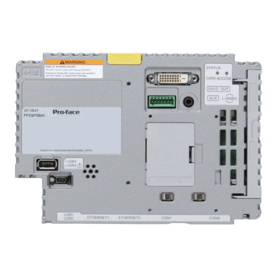
Sp-5B40 / Sp-5B41
LED Indications
Specifications
Electrical Specifications
Environmental Specifications
Interface
Interface Caution
Serial Interface
Auxiliary Output/Speaker Output Interface (AUX)
DVI-D Output Interface (Only for Open Box)
Installation
Installation Procedure
Removal Procedure
Connecting to the USB Interface
Attaching USB Clamp Type a (1 Port)
AUX Connector
Cleaning this Product
Standards
Advertisement
Quick Links
1
Table of Contents
2
Sp-5B10
3
Sp-5B40 / Sp-5B41
4
Led Indications
5
Interface
6
Serial Interface
7
Installation Procedure
8
Connecting to the Usb Interface
Download this manual
SP5000 Series (Box Module)
Installation Guide
HRB78714_07_EN
Table of
Contents
Previous
Page
Next
Page
1
2
3
4
5
Advertisement
Table of Contents
Need help?
Do you have a question about the SP-5B10 and is the answer not in the manual?
Ask a question
Questions and answers
Related Manuals for Pro-face SP-5B10
Control Unit Pro-face GP4000 Series Replacement Manualbook
(45 pages)
Control Unit Pro-face PFXZXMADSM31 Installation Manual
Display module/rear module separation cable (4 pages)
Control Unit Pro-face PL Series Installation Manual
Dim module (8 pages)
Control Unit Pro-face PRO-iO2 Installation Manual
(20 pages)
Control Unit Pro-face GP-377 Series Installation Manual
(10 pages)
Control Unit Pro-face GP-37W3 Series User Manual
Pro-designer compatible (49 pages)
Control Unit Pro-face AGP3000 Quick Start Manual
To yaskawa j7 drive via modbus rtu (3 pages)
Control Unit Pro-face GP377R-TC11-24V Installation Manual
(9 pages)
Control Unit Pro-face CA2-ISOALL422-01 Installation Manual
Isolation unit (6 pages)
This manual is also suitable for:
Sp-5b41
Sp-5b40
Pfxsp5b10
Pfxsp5b40
Pfxsp5b41
Table of Contents
Print
Rename the bookmark
Delete bookmark?
Delete from my manuals?
Login
Sign In
OR
Sign in with Facebook
Sign in with Google
Upload manual
Upload from disk
Upload from URL


Need help?
Do you have a question about the SP-5B10 and is the answer not in the manual?
Questions and answers