
Related Manuals for Beninca KER


Summary of Contents for Beninca KER
- Page 1 L8542498 04/2011 rev 3 UNIONE NAZIONALE COSTRUTTORI AUTOMATISMI PER CANCELLI, PORTE SERRANDE ED AFFINI...
- Page 2 Dichiarazione CE di conformità Déclaration CE de conformité EC declaration of confirmity Declaracion CE de conformidad Deklaracja UE o zgodności EG-Konformitatserklarung Con la presente dichiariamo che il nostro prodotto We hereby declare that our product Hiermit erklaren wir, dass unser Produkt Nous déclarons par la présente que notre produit Por la presente declaramos que nuestro producto Niniejszym oświadczamy że nasz produkt...
- Page 3 F3 KER230: F6,3A F3 KER115: F10A F2: F315 mA LOCK Lock 12Vac DIP5: OFF N GND LAMP 115/230Vac 40W max...
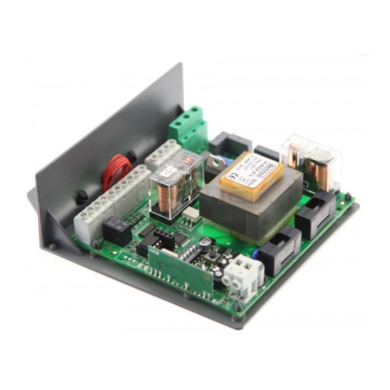
- Page 4 KER control unit The KER electronic control unit can be used to control 1 motor with power not higher than 750W. GENERAL WARNINGS a) The wire connections and the operating logic should be in compliance with regulations in force. b) The cables featuring different voltage should be physically detached, or adequately insulated by an additional shield of at least 1 mm.
- Page 5 HOW TO CHECK CONNECTIONS: 1) Cut off power supply. 2) Manually release the door and push it for about half stoke. Lock the door again. 3) Restore power supply. 4) Send a step-by-step control through P2 push-button, P.P. input or radio-control signal. 5) The door must move in the opening phase.
- Page 6 Once the desired torque is selected, to learn this setting move the DIP1 to OFF. RADIO LEARNING (DIP1:OFF) The KER control unit is equipped of a built-in radio module for the reception of variable code, with 433.92 MHz frequency. To use a remote control, its code must be stored in memory. The memorisation procedure is shown hereunder.
- Page 7 Note: The transmitters are stored in an EPROM memory (U2), which can be removed and repositioned in a new KER control unit, if required. For safety reasons, it is not possible to store transmitter codes into memory during the opening/ closing phases of the motor.
Need help?
Do you have a question about the KER and is the answer not in the manual?
Questions and answers