Table of Contents
Advertisement
Quick Links
Advertisement
Table of Contents

Related Manuals for Fermax iLoft VDS Dominium


Summary of Contents for Fermax iLoft VDS Dominium
- Page 1 VDS Dominium Monitor V4.0 ANUAL COD. 97754Ic V06_16...
-
Page 3: Table Of Contents
ANUAL VDS D - V4.0 OMINIUM ONITOR Index General Description ______________________________________________________________ 3 Operating Modes ____________________________________________________________________ 4 1.1.1 Home Automation Mode ____________________________________________________________________ 4 1.1.2 Energy Efficient Mode ______________________________________________________________________ 4 About using the BUSing system ________________________________________________________ 4 Technical description _____________________________________________________________ 5 Operating in Home Automation mode _______________________________________________ 6 Main screen ________________________________________________________________________ 6 3.1.1 Browsing between pages ____________________________________________________________________ 7... -
Page 4: General Description
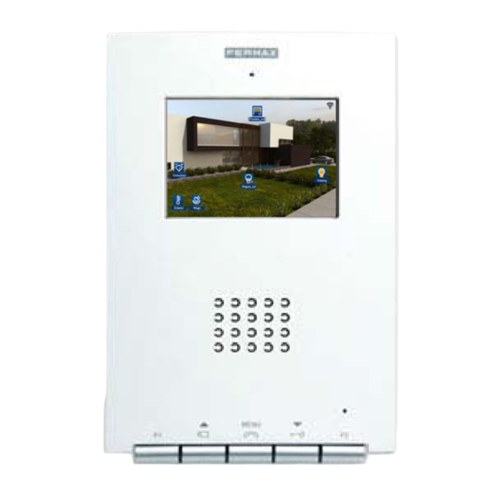
ENERAL ESCRIPTION The iLoft VDS Dominium Monitor is a video entry unit as a result of FERMAX’s joint venture with ingenium. This ® monitor has a 3.5” colour touch screen that allows you to monitor and control the home automation BUSing system quickly and intuitively via allusive icons in each of the installation’s rooms. -
Page 5: Operating Modes
Technical and Security Alarms. Each BUSing device requires address and parameters programming to be able to integrate into an installation. This programming must be performed by a specialised technician via the SIDE Fermax programming software Graphic control 4 of 52... -
Page 6: Technical Description
It emerges from the wall 14 mm once installed FERMAX Flush Mounted Box Size: 108 (width) x 158 (height) x 45 (depth) mm Standard Flush Mounted Box Size: 114 (width) x 174 (height) x 50 (depth) mm ... -
Page 7: Operating In Home Automation Mode
ANUAL VDS D - V4.0 OMINIUM ONITOR PERATING IN UTOMATION MODE The graphic interface is divided into three main areas: A central area with the installation’s maps over which the control icons are distributed over the different equipment. An upper bar which becomes visible upon dragging the map main screen down. In this bar we can activate different scenarios programmed in SIDE, besides being able to create new scenarios. -
Page 8: Browsing Between Pages
ANUAL VDS D - V4.0 OMINIUM ONITOR 3.1.1 B ROWSING BETWEEN PAGES Slide your finger over the screen to the right or left to browse between pages 3.1.2 C OMMON CONS 3.1.2.1 LIGHT BULBS To light up or turn off any of the light switches just click over the light bulb drawn on the page. When the light bulb is yellow, the light is lit, otherwise when it is blue it is off. - Page 9 ANUAL VDS D - V4.0 OMINIUM ONITOR In the new drop down window, drag your finger over the shutter to adjust the opening level, dragging your finger up or down on the touch surface. When the user lifts his/her finger the open level is set, the shutter level window will close and the actuator will activate the corresponding output.
- Page 10 ANUAL VDS D - V4.0 OMINIUM ONITOR By clicking on a thermostat icon, a box appears to be able to turn the thermostat on or on, adjust the temperature, establish the operating mode, check data history and configure up to 10 different scenarios with the schedule.
- Page 11 ANUAL VDS D - V4.0 OMINIUM ONITOR Remote mode and operating mode: Summer (demand for cooling) Winter (demand for heat) Mixed When the icons are in white the selection is deactivated. When they are in yellow, the selection is activated and it is the mode currently in operation.
- Page 12 ANUAL VDS D - V4.0 OMINIUM ONITOR Finally, you can set the temperature for the timer , and it will be defined in the thermostat when the scenario turns on. This temperature can be edited by pressing the number and sliding your finger up without releasing it to increase, down to reduce it.
- Page 13 ANUAL VDS D - V4.0 OMINIUM ONITOR 3.1.2.6 DETECTORS Detector in standby Detector activated This icon is used to show the installation’s presence detector’s status. Detector on switch : This icon is to manually turn the detector on, that is, by pressing on this icon the SRBUS detects movement and operations normally.
- Page 14 ANUAL VDS D - V4.0 OMINIUM ONITOR Each channel can have its maximum limit set, which the consumption measurements should remain under. If it surpasses this range, the installation would perform a series of actions to correct the excess in demand according to the configured parameters.
- Page 15 ANUAL VDS D - V4.0 OMINIUM ONITOR status (including percentage of charge), pipe status or equipment autonomy. As a complement, you can turn the lighting on or off to check its proper performance. As you can see, in the middle it shows the lighting’s status, offering information on its battery percentage, tube or autonomy.
-
Page 16: Upper Scenario Row
ANUAL VDS D - V4.0 OMINIUM ONITOR PPER SCENARIO ROW The upper bar, which appears after swiping the main screen down, displays all of the configured scenarios in the project since the SIDE, and also includes an icon on the left (always visible) that allows you to create new scenarios, along with editing or deleting those that have been created on the screen itself. - Page 17 ANUAL VDS D - V4.0 OMINIUM ONITOR 3.2.2.1 ADD A SCENARIO By clicking on the add a new scenario icon , an on-screen keypad appears with which you can name a new event to later be associated to the desired status icons. 3.2.2.2 REMOVE A SCENARIO Press the remove a scenario icon , to delete the selected event (of those previously configured on the...
-
Page 18: Lower Control Bar
ANUAL VDS D - V4.0 OMINIUM ONITOR To add events to a scenario, just drag the corresponding icons from the lower horizontal bar to the icon box on the upper right. If you want to delete an event, just mark the corresponding icon by pressing it, and press the remove button on the right of the screen: If adding icons, the status of the output associated to this icon remains linked to the scenario, so that when the scenario is executed, it will establish the statuses associated upon editing the scenario. -
Page 19: Notepad
ANUAL VDS D - V4.0 OMINIUM ONITOR By pressing on the different available icons in the lower bar, new windows appear with the functions of each section. In order to close the drop downs, just confirm the actions within the drop-down panel, or by re-pressing the corresponding icon via which we open a new window. - Page 20 ANUAL VDS D - V4.0 OMINIUM ONITOR To access the notepad you must press on the corresponding icon located on the lower bar. To draw or jot down a note simply slide your finger over the screen. If you want to delete something you can select the eraser icon available in the left area.
-
Page 21: Technical Alarms Notifications
ANUAL VDS D - V4.0 OMINIUM ONITOR 3.3.2 T ECHNICAL LARMS NOTIFICATIONS The iLoft video entry unit allows for up to 5 different technical alarms to be displayed when produced in the installation, whether flooding, gas, fire, etc. Whenever a technical alarm has been generated, the screen warns the user via an icon in the upper right corner next to the WiFi signal icon , and blinking the technical alarms icon in the lower bar’s menu options. -
Page 22: Schedule
ANUAL VDS D - V4.0 OMINIUM ONITOR For each technical alarm on the installation, you can link the IP cameras to send images of the incident together with the alarm notification email when it goes off. The technical alarms menu option is which will give us access to assigning these cameras for the notification of each alarm. - Page 23 ANUAL VDS D - V4.0 OMINIUM ONITOR 3.3.3.1 ADD SCHEDULE On the vertical list on the left side, you find the set of schedules programmed on the monitor. To add a schedule just press on the icon and a new window appears to select the scenario, with two columns, one on the left with the already created schedules, and another on the right with the available periods to schedule.
- Page 24 ANUAL VDS D - V4.0 OMINIUM ONITOR Add year: Add all the days of the year for the same schedule. Add the whole month: Add the schedule for every day of the month in which the calendar on the right is.
- Page 25 ANUAL VDS D - V4.0 OMINIUM ONITOR 3.3.3.3 EDIT A SCHEDULE To edit a previously made schedule on the monitor, you must select it on the vertical list on the left side of the screen. Once selected, pressing the icon, the previously described screen drops down to add a schedule. On this screen we can add or delete schedules for the previously selected scenario, taking advantage of the repetition levels as discussed in point 3.3.3.1 Add schedule.
-
Page 26: Intruder Alarm
ANUAL VDS D - V4.0 OMINIUM ONITOR If in the previous example we click on the icon, the schedule remains deactivated and does not execute until reactivated by clicking on the icon. 3.3.4 I NTRUDER LARM The intruder alarm icon, identified below, allows you to activate/deactivate the intruder alarm. After pressing the indicated icon, a numeric keypad appears on the screen to enter the user code: 1234 (By default). -
Page 27: Presence Simulation
ANUAL VDS D - V4.0 OMINIUM ONITOR When the intruder alarm is deactivated, the icon is fixed in the lower horizontal bar. Once the intruder alarm system is activated, the icon blinks continuously. 3.3.5 P RESENCE IMULATION The icon indicated in the following image allows us to activate/deactivate the presence simulation in the home. By pressing it, a dialogue box will appear in which you have to confirm or cancel the presence simulation system’s activation/deactivation: Then the following is displayed: To activate:... -
Page 28: Configuration Menu
ANUAL VDS D - V4.0 OMINIUM ONITOR When the presence simulation is deactivated, the icon is fixed in the lower horizontal bar. Once the presence simulation is activated, the icon blinks continually. ONFIGURATION In this section we can edit the different configurable parameters, which have 9 options that are described below: Once the configuration icon is pressed, a window with the menu options opens 3.4.1 WIFI... - Page 29 ANUAL VDS D - V4.0 OMINIUM ONITOR To edit the fields just press on them and use the on-screen keypad that drops down. Within the editable parameters: SSID: Public name of the wireless network to which video entry unit connects to. When the editable fields are selected, a list with all of the available WiFi networks drops down, displaying each of their coverage.
- Page 30 ANUAL VDS D - V4.0 OMINIUM ONITOR control the installation may connect to (PCs, tablets, smartphones, etc). The wireless network will have the visible name as indicated in the SSID field (Option “Other…” from the editing drop-down menu) and the password from the password field. For the password, the type of encryption is that which we mark in the selectable field WEP, WPA, or no encryption if we select none.
- Page 31 ANUAL VDS D - V4.0 OMINIUM ONITOR This option allows you to establish the screen’s IP address, subnet mask and local network’s gateway to connect The following are the configurable parameters: IP Address: The screen’s IP address within the local network. ...
-
Page 32: Security
ANUAL VDS D - V4.0 OMINIUM ONITOR To confirm saving these changes. To save the changes press , to cancel them press 3.4.2 S ECURITY In this menu option the user can activate monitor usage protection via a 4 digit password, or modify this administrator screen password, which is necessary to carry out actions like activating/deactivating the intruder alarm. - Page 33 ANUAL VDS D - V4.0 OMINIUM ONITOR On the right side, the application lets you modify the video entry unit’s administrator password, using various menu options. Once the change is accessed, the screen asks for the current password, necessary to be able to continue with the process.
-
Page 34: System Restart
ANUAL VDS D - V4.0 OMINIUM ONITOR In order to guarantee proper insertion with the touch screen, and to avoid errors when entering the password, it is asked for a second time to compare it with the first one. If the new password is entered erroneously, or the two consecutive attempts do not coincide, the screen will display the corresponding error message. -
Page 35: Firmware Update
ANUAL VDS D - V4.0 OMINIUM ONITOR Reboot: Restart the system to resolve any inconsistent situation that could have been produced. The video entry unit restarts again after a few seconds. Restore Data: The application restores the internal database, and restarts it as a clean system, maintaining the project but without historical registries, schedules, new edited scenarios, etc. -
Page 36: Time Zone
ANUAL VDS D - V4.0 OMINIUM ONITOR The new equipment without programs launches a periodic message to the bus, which the video entry unit can receive and display on screen as shown below. For each equipment, you can 3.4.6 T IME ZONE This option helps select the time zone in which you find yourself, so as to set the screen’s clock to the corresponding zone, guaranteeing proper execution of the timed scenarios. -
Page 37: Email List
ANUAL VDS D - V4.0 OMINIUM ONITOR 3.4.7 E MAIL LIST You can receive notifications from the video entry unit via email. For this, just edit the email list with those used for different notifications. Using the + and - buttons, the user has the option of adding new email addresses to the list or delete the selected ones. -
Page 38: Register Installation
ANUAL VDS D - V4.0 OMINIUM ONITOR 3.4.9 R EGISTER NSTALLATION This menu option is indispensable for registering the project on the ingenium server and for making it available for remote control via the ingenium applications for PC, iOS, Android and Samsung SmartTV. Accessing this tool you must press on "Register device,"... -
Page 39: Weather Forecast
ANUAL VDS D - V4.0 OMINIUM ONITOR decide to delete the server’s project, the screen will request confirmation from the user prior to starting the process. After confirming, the project is deleted from the server, and may not be controlled remotely. If you want to upload the project up to the server again, the user can do so by registering their device again and defining the username and password. - Page 40 ANUAL VDS D - V4.0 OMINIUM ONITOR 3.5.1.1 EDITING LOCATIONS The screen allows you to add or delete forecast locations for future searches. For this just use the icons on the lower-right, pressing the button to add a new city, and the button to delete the current city you are currently searching.
- Page 41 ANUAL VDS D - V4.0 OMINIUM ONITOR Once selected from the vertical list of results, to add the location to our screen just press the icon amongst the vertical drop down arrows, to add it to the iLoft memory. The new location is added in the last position of the already configured list.
-
Page 42: Operating In Energy Efficiency Mode
ANUAL VDS D - V4.0 OMINIUM ONITOR PERATING IN NERGY FFICIENCY In this mode you are optimising the control of thermostats and consumption meters, along with viewing their status instantaneously and/or accumulated in the established period. The application of efficiency is divided into two large groups: ... - Page 43 ANUAL VDS D - V4.0 OMINIUM ONITOR specific element to control is selected, we can act upon it in the central part of the screen, over the information displayed. For thermostats, you can activate or deactivate the thermostat (On- Yellow, Off - White). The average temperature continues functioning to include registries but not make decisions on how to turn the boiler on or off, for example), view the measured temperature, set the temperature with the + or - buttons, and the operating mode by pressing on any of them.
-
Page 44: View
ANUAL VDS D - V4.0 OMINIUM ONITOR For the consumption meters, you can establish the threshold for each channel upon which programmed commands will be executed if this value is surpassed. This value can be changed by using the side arrows for each one. -
Page 45: Total Registries Period
ANUAL VDS D - V4.0 OMINIUM ONITOR 4.2.1 T OTAL REGISTRIES PERIOD This menu option allows you to select the range of dates to view the total registries. As a quick access, you can define them to the current day, for the last week or last month. For other customised periods, select the last option and show a calendar that gives the option to choose the range's start date and end date. -
Page 46: Instantaneous Values
ANUAL VDS D - V4.0 OMINIUM ONITOR After having completed the selection process, the calendar icon shows the established range in the lower part. 4.2.2 I NSTANTANEOUS VALUES The application includes information issued from thermostats or consumption meters, and is capable of processing and showing them in a real evolution graph, with up-to-date consumption instantaneously. -
Page 47: Total Registries
ANUAL VDS D - V4.0 OMINIUM ONITOR If the consumption meter has more than one channel, you can select the one that interests you most in the listed circles on the right of the screen by simply pressing what was desired. 4.2.3 T OTAL EGISTRIES... -
Page 48: Configuration Menu
ANUAL VDS D - V4.0 OMINIUM ONITOR ONFIGURATION The configuration menu, accessed via the button in the upper right corner, has 9 options. The explanation of each of these options is found in section 3.4 Configuration Menu of this manual. Graphic control 47 of 52... -
Page 49: Recovery Screen
ANUAL VDS D - V4.0 OMINIUM ONITOR ECOVERY SCREEN This screen is shown when the video door-entry system enters in an inconsistent mode, facilitating the tools to restore specific values or to recuperate the device from operating problems. The screen has four options: Restart the complete video entry unit project , configure the WiFi network on the screen , restore the vital application files from the ingenium server for the screen to work... -
Page 50: Restore Default Settings
ANUAL VDS D - V4.0 OMINIUM ONITOR 5.1.4 R ESTORE DEFAULT SETTINGS This option lets you restore the screen to the default setting. Sometimes this option can solve stability problems relative to the screen’s function. When you select this tool, the screen asks for a user password to confirm the operation. -
Page 51: Installation
ANUAL VDS D - V4.0 OMINIUM ONITOR NSTALLATION Graphic control 50 of 52... - Page 52 NOTES...
Need help?
Do you have a question about the iLoft VDS Dominium and is the answer not in the manual?
Questions and answers