Advertisement
Quick Links
"
PrimeTec
User Manual
2"
Introduction
1
Box Contents
1.1
3"
E
Markings for
safety curtain
adjustment
4"
(See page 6)
F
G
PrimeTec Self-Adhesive Mounting Template
Screw
5"
Dia. 1/2" (12 mm) for cable exit
Tools Required for Installation
1.2
- Ladder
- Tape measure
- Level
- Wire cutter
- 4 gauge (5 mm dia.) wire stripper for cable sleeve
Parts of the Sensor
1.3
A
E
F
D
Markings for
safety curtain
adjustment
(See page 6)
E
C
B
A
Screw
Align with center of door header
C
B
D
I
J K
L
M
Combined microwave (motion)/active infrared (safety) sensor
for activating and protecting automatic pedestrian sliding doors
EN ISO
This product meets or exceeds
9001
ANSI standard 156.10 as independently
Quality
international
level
tested by TÜV Rheinland North America
Combined microwave (motion)/active infrared (safety) sensor
for activating and protecting automatic pedestrian sliding doors
0641&7%6+10
Box Contents
9001
EN ISO
This product meets or exceeds
Quality
international
level
ANSI standard 156.10 as independently
tested by TÜV Rheinland North America
for activating and protecting automatic pedestrian sliding doors
Combined microwave (motion)/active infrared (safety) sensor
Box Contents
0641&7%6+10
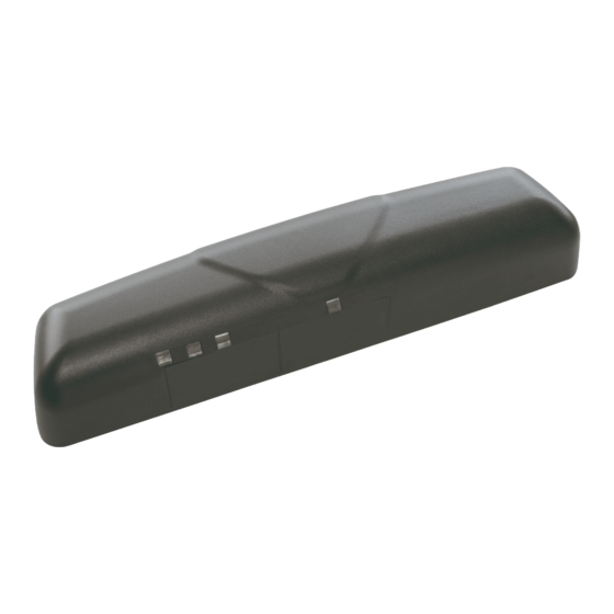
Sensor cover
The box contains the following items:
PrimeTec sensor
Quality
ternational
9001
N ISO
level
ANSI standard 156.10 as independently
tested by TÜV Rheinland North America
This product meets or exceeds
Markings for
Self-tapping mounting screws (2)
Instruction manual
Click-in safety curtain masking covers (2)
Instruction manual
Self-tapping mounting screws (2)
- Electric drill with 1/2" (12 mm) drill bit
sensor to door operator
adjustment
Tools required for installation:
0641&7%6+10
Box Contents
- Ladder
PrimeTec sensor
- Level
- Tape measure
- 4 gauge (5 mm dia.) wire stripper for cable sleeve
- Wire cutter
- 26 gauge (0.14 mm²) wire stripper for single wires
- Phillips head screwdriver (size #1)
Marking for
Self-adhesive mounting template
Click-in safety curtain masking covers (2)
The box contains the following items:
10' (3 m) 8-wire electrical cable to connect
(See page 6)
Sensor cover
safety curtain
- Flathead screwdriver 1/8" (#1/ 3.6 mm)
Combined microwave (motion)/active infrared (safety) sensor
for activating and protecting automatic pedestrian sliding doors
PrimeTec sensor
(See page 6)
adjustment
safety curtain
sensor to door operator
10' (3 m) 8-wire electrical cable to connect
Self-adhesive mounting template
Parts of the Sensor
- Electric screwdriver with phillips head (size #2)
- Tape measure
- Ladder
Tools required for installation:
PrimeTec Self-Adhesive Mounting Template
Sensor cover
- Wire cutter
- Level
- 4 gauge (5 mm dia.) wire stripper for cable sleeve
- 26 gauge (0.14 mm²) wire stripper for single wires
Screw
D a. 1/2" (12 mm) for cable exit
Align with center of door header
Sc ew
- Phillips head screwdriver (size #1)
- Flathead screwdriver 1/8" (#1/ 3.6 mm)
- Electric drill with 1/2" (12 mm) drill bit
- Electric screwdriver with phillips head (size #2)
Parts of the Sensor
Click-in safety curtain masking covers (2)
Instruction manual
Self-tapping mounting screws (2)
10' (3 m) 8-wire electrical cable to connect
sensor to door operator
PrimeTec Self-Adhesive Mounting Template
Self-adhesive mounting template
Screw
Screw
Align with center of door header
Dia. 1/2" (12 mm) for cable exit
Tools Required for Installation
- Ladder
- 26 gauge (0.14 mm²) wire stripper for single wires
- Tape measure
- Phillips head screwdriver (size #1)
- Level
- Flathead screwdriver 1/8" (#1/ 3.6 mm)
- Wire cutter
- Electric drill with 1/2" (12 mm) drill bit
- 4 gauge (5 mm dia.) wire stripper for cable sleeve
- Electric screwdriver with phillips head (size #2)
Parts of the Sensor
S
- 26 gauge (0.14 mm²) wire stripper for single wires
- Phillips head screwdriver (size #1)
- Flathead screwdriver 1/8" (#1/ 3.6 mm)
- Electric drill with 1/2" (12 mm) drill bit
- Electric screwdriver with phillips head (size #2)
N
O
Page 1
PrimeTec sensor
A
B
Sensor cover
C
Click-in safety curtain masking covers (2)
Instruction manual
D
Self-tapping mounting screws (2)
10' (3 m) 8-wire electrical cable to connect
F
sensor to door operator
Self-adhesive mounting template
G
A
Cover
Safety sensor
indicator LED window
Safety curtain window
C
Motion sensor
D
indicator LED window
E
Cable bushing
F
Cable connector
G
(for new installations)
Screw terminals
H
(for retrofit installations)
Active infrared safety curtain lens
I
F
(safety sensor)
Safety sensor indicator LED (red)
J
Red button (function)
K
L
Black button (value)
Motion sensor indicator LED (green)
M
N
Safety curtain adjustment screw
Microwave module (motion sensor)
O
P
LCD display
3"
Advertisement

Related Manuals for Bircher Reglomat PrimeTec

Summary of Contents for Bircher Reglomat PrimeTec
-
Page 1: User Manual
- Electric screwdriver with phillips head (size #2) Parts of the Sensor Tools required for installation: - Ladder - Tape measure PrimeTec Self-Adhesive Mounting Template Sensor cover Markings for - Level - Wire cutter - 4 gauge (5 mm dia.) wire stripper for cable sleeve - 26 gauge (0.14 mm²) wire stripper for single wires... - Page 2 -Ensure (e.g. by walk testing) that installation is in compliance with all applicable standards (e.g. ANSI 156.10) after completion of installation. -If the sensor sustains damages (e.g falls), replace it with a new unit. -If a satisfactory solution cannot be achieved after troubleshooting a problem, please call Bircher Reglomat at 800-252-1272 or visit our website at www.bircherreglomat.com.
- Page 3 Route the cable in the cable channels so it is flush against the back of the sensor. Several options are shown- select the best option for your installation. Positioning & Attaching the Sensor Middle of door opening PrimeTec Self-Adhesive Mounting Template Screw Screw Align with center of door header Dia.
- Page 4 Electrical Connections 4-Wire Connection: Standard Option (Combined motion & safety outputs) New installation using gray cable with plug Retrofit installation using detachable screw terminal Black 11.5 - 36 VDC/ Power 10 - 28 VAC Cable White 11.5 - 36 VDC/ Motion/ Motion/ Power...
- Page 5 Initialization Green LED Red LED REMOVE all foreign OBJECTS that are not part of the normal (Motion) (Safety door system environment BEFORE powering on the sensor. Make sure no people or moving objects are in the door area, otherwise correct startup will not be possible. The alternate flashing LED’s indicate the initialization (teach-in) of the sensor.
- Page 6 Adjusting the Safety Curtain Distance from the Door – – + + 7° Please refer to current published For assistance, use the measu- 2° (factory setting) ANSI standard for exact measure- ring guide on the front of the 0° manual to determine this ments.
- Page 7 Adjusting the Motion Field Size to Meet Standard Requirements In order to meet ANSI standard 156.10, the sensor’s motion field pattern must cover the ANSI-specified field dimensions (designated by x’s in the drawing). Please refer to the current published ANSI standard for details.
- Page 8 Configuration (Operator Buttons) Entering Configuration Mode LCD panel location Red button Black button Shortly press Once in configura- Start in = Motion Functions Once in the desired fun- Once all changes End in the red & tion mode, the circ- = Safety Functions complete, ction block, press the...
- Page 9 Safety Curtain Settings Function Values Description Safety Functions (Select with (Select with Factory settings in bold with * RED button) BLACK button) 2 = Regular sensitivity* 2, 3 Sensitivity 3 = Snow mode Teach-In Time 1 = 10 seconds 2 = 30 seconds* The amount of time until 1 - 5 3 = 60 seconds...
-
Page 10: Troubleshooting
Door stays open 1. Change output logic of safety or motion output (NO/NC) (section 8). If a satisfactory solution cannot be achieved after troubleshooting a problem, please call Bircher Reglomat at 800-252-1272 or visit our website at www.bircherreglomat.com. DO NOT LEAVE ANY PROBLEMS UNRESOLVED! DO NOT SACRIFICE SAFETY FOR ANY REASON! - Page 11 Besam UniSlide Door Operator 6-Wire Connection: Recommended option (enhanced performance through separate motion & safety outputs) Common Door Operator Wiring Diagrams Other options available - please see PrimeTec manual or contact Bircher Reglomat for assistance. Besam UniSlide 10.1 PrimeTec Sensor must be programmed for this wiring configuration.
- Page 12 For more details, please see section 8. Black inside & outside PrimeTecs Red inside & outside PrimeTecs Alternatively black inside & outside PrimeTecs Alternatively red inside & outside PrimeTecs White outside PrimeTec Green outside PrimeTec White inside PrimeTec Green inside PrimeTec Brown inside & outside PrimeTecs Blue inside &...
- Page 13 Ext. Sw IN and select "Aux. Sw"; next scroll down and select "Safety Beam". Emerg.Opn/Cls Aux. Sw Input disabled Emerg.Opn/Cls Aux. Sw Connect the PrimeTec’s as shown below. disabled Safety Beam Aux. Sw Safety Beam Sidescrn sensr Sidescrn sensr SERIES 5100 019.808.187...
- Page 14 Press and hold the black value button for 8 seconds to separate motion & safety outputs. For more details, please see section 8. IN 24V IN 24V OUT 24V IN OUT 24V PrimeTec B ES/01 Inside Brown & Orange Blue Black & White Green PrimeTec B ES/01 Outside Brown &...
- Page 15 - Connect the equipment into an outlet on a circuit different from that to which the receiver is connected. - Consult the dealer or an experienced radio/TV technician for help. Warning: Changes or modifications to this equipment not expresssly approved by Bircher Reglomat may void the FCC authorization to operate this equipment.
- Page 16 FFC: UXS2 6902A-UXS2 Important note: Bircher Reglomat reserves the right to change any information in this document without notice. For the latest version, please visit www.bircherreglomat.com or call 800-252-1272 to request a copy. Bircher Reglomat 870 Pratt Avenue N Schaumburg, IL 60193...
Need help?
Do you have a question about the PrimeTec and is the answer not in the manual?
Questions and answers