Sign In
Upload
Download
Table of Contents
Contents
Add to my manuals
Delete from my manuals
Share
URL of this page:
HTML Link:
Bookmark this page
Add
Manual will be automatically added to "My Manuals"
Print this page
×
Bookmark added
×
Added to my manuals
Manuals
Brands
F5 Manuals
Multi-service Platforms
i5000 Series
Setting up
F5 i5000 Series Setting Up
Platform
Hide thumbs
Also See for i5000 Series
:
Platform manual
(72 pages)
1
2
Table Of Contents
3
4
5
6
7
8
9
10
11
12
13
14
15
16
17
18
19
20
21
22
23
24
25
26
27
28
29
30
page
of
30
Go
/
30
Contents
Table of Contents
Bookmarks
Table of Contents
Table of Contents
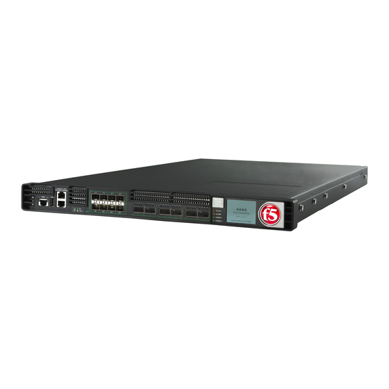
Platform Overview
About I5000/I7000/I10000/I11000 Series Models
About the Platform
Hardware Included with the Platform
Peripheral Hardware Required
Platform Installation
About Installing the I5000/I7000/I10000/I11000 Series Platform
About the Quick-Install Rails
Quick-Install Rail Kit Hardware
Install the Rail Lock Brackets
About Grounding the Platform
Connect the Ground Lug to the Ground Terminal
Connect the Cables and Other Hardware
Configure a Management IP Address Using the LCD
License the Platform
Environmental Guidelines
General Environmental and Installation Guidelines
Chassis Rack-Mount Spatial Requirements
Guidelines for Power Supplies
Guidelines for AC-Powered Equipment
Guidelines for DC-Powered Equipment
Platform Airflow Diagram
Legal Notices
Advertisement
Quick Links
1
About I5000/I7000/I10000/I11000 Series Models
Download this manual
Setting Up the i5000/i7000/i10000/i11000
Series Platform
MAN-0620-08
Table of
Contents
Previous
Page
Next
Page
1
2
3
4
5
Advertisement
Table of Contents
Need help?
Do you have a question about the i5000 Series and is the answer not in the manual?
Ask a question
Questions and answers
Related Manuals for F5 i5000 Series
Network Hardware F5 i5000 Series Platform Manual
(72 pages)
Multi-service Platforms F5 i5820-DF Setting Up
Platform (30 pages)
Multi-service Platforms F5 i7820-DF Setting Up
Platform (30 pages)
Multi-service Platforms F5 i10000-D Setting Up
Platform (30 pages)
Multi-service Platforms F5 2000 Series Manual
(28 pages)
This manual is also suitable for:
I7000 series
I10000 series
I11000 series
I5820-df
I7820-df
I7000-d
...
Show all
I10000-d
I10810
I10610
Table of Contents
Print
Rename the bookmark
Delete bookmark?
Delete from my manuals?
Login
Sign In
OR
Sign in with Facebook
Sign in with Google
Upload manual
Upload from disk
Upload from URL


Need help?
Do you have a question about the i5000 Series and is the answer not in the manual?
Questions and answers