Table of Contents
Advertisement
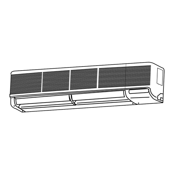
SPLIT-TYPE, HEAT PUMP AIR CONDITIONERS
SPLIT-TYPE, AIR CONDITIONERS
TECHNICAL & SERVICE MANUAL
Series PKA
Indoor unit
[Model names]
PKA-RP2.5FAL
PKA-RP3FAL
PKA-RP4FAL
Indoor unit
Remote controller
Wall Mounted
[Service Ref.]
PKA-RP2.5FAL
PKA-RP3FAL
PKA-RP4FAL
Model name
indication
R407C/R410A
CONTENTS
INDOOR AND OUTDOOR UNITS ····················2
2. SAFETY PRECAUTION ····································3
3. PART NAMES AND FUNCTIONS·····················6
4. SPECIFICATIONS ·············································8
5. DATA································································14
6. OUTLINES AND DIMENSIONS ······················33
7. WIRING DIAGRAM ·········································35
8. REFRIGERANT SYSTEM DIAGRAM ·············36
9. TROUBLESHOOTING·····································37
10. DISASSEMBLY PROCEDURE ·······················47
11. RoHS PARTS LIST··········································50
12. OPTIONAL PARTS··························Back Cover
August 2013
No.OC301
REVISED EDITION-B
Revision:
• Part No. of TOP PLATE (page
50, 51) has been modified in
REVISED EDITION-B.
• Please void OC301
REVISED EDITION-A.
Note:
• This manual does not cover
outdoor units. When servicing
them, please refer to service
manual OC261, OC285,
OC294, OC298 and this
manual in a set.
• RoHS compliant products
have <G> mark on the spec
name plate.
Advertisement
Table of Contents

Subscribe to Our Youtube Channel
Related Manuals for Mitsubishi PKA-RP2.5FAL


Summary of Contents for Mitsubishi PKA-RP2.5FAL
-
Page 1: Table Of Contents
Series PKA Wall Mounted R407C/R410A Indoor unit Revision: [Model names] [Service Ref.] • Part No. of TOP PLATE (page 50, 51) has been modified in PKA-RP2.5FAL REVISED EDITION-B. PKA-RP2.5FAL • Please void OC301 PKA-RP3FAL REVISED EDITION-A. PKA-RP3FAL Note: PKA-RP4FAL • This manual does not cover PKA-RP4FAL outdoor units. -
Page 2: Combination Of Indoor And Outdoor Units
(R410A Inverter) Outdoor unit [OC294 REVISED EDITION-A] Heat pump type Indoor unit PUHZ-RP 2.5VHA 3VHA 4VHA 4VHA — — PKA-RP2.5FAL PKA-RP3FAL — — PKA-RP4FAL — — (R407C Fixed speed) Outdoor unit [OC285] Outdoor unit [OC298] Heat pump type Cooling only type... -
Page 3: Safety Precaution
SAFETY PRECAUTION CAUTIONS RELATED TO NEW REFRIGERANT Cautions for units utilizing refrigerant R407C Do not use the existing refrigerant piping. Use liquid refrigerant to seal the system. The old refrigerant and lubricant in the existing piping If gas refrigerant is used to seal the system, the composition contains a large amount of chlorine which may cause the of the refrigerant in the cylinder will change and performance lubricant deterioration of the new unit. - Page 4 [3] Service tools Use the below service tools as exclusive tools for R407C refrigerant. Tool name Specifications Gauge manifold ·Only for R407C. ·Use the existing fitting SPECIFICATIONS. (UNF7/16) ·Use high-tension side pressure of 3.43MPa·G or over. Charge hose ·Only for R407C. ·Use pressure performance of 5.10MPa·G or over.
- Page 5 CAUTIONS RELATED TO NEW REFRIGERANT Cautions for units utilizing refrigerant R410A Use new refrigerant pipes. Do not use refrigerant other than R410A. In case of using the existing pipes for R22, be careful with If other refrigerant (R22 etc.) is used, chlorine in refrige- the followings.
-
Page 6: Part Names And Functions
Unit Gravimeter [3] Service tools Use the below service tools as exclusive tools for R410A refrigerant. Specifications Gauge manifold ·Only for R410A ·Use the existing fitting specifications . (UNF1/2) ·Use high-tension side pressure of 5.3MPa·G or over. Charge hose ·Only for R410A ·Use pressure performance of 5.09MPa·G or over. -
Page 7: Wireless Remote Controller
Wireless remote controller When cover is open. display CHECK TEST RUN CHECK&TEST RUN display indicates that the unit is being checked or test-run. display MODEL SELECT Blinks when model is selected. display Lights up while transmission to the indoor unit is mode using switches. display SET TEMP. -
Page 8: Specifications
SPECIFICATIONS 4-1. Heat pump type (1) Service Ref. PKA-RP2.5FAL Item Function Cooling Heating Btu/h 20,500 23,900 Capacity 6,000(2,700~6,700) 7,000(2,800~8,200) 1.55 2.01 Total input Service Ref. PKA-RP2.5FAL Power supply(phase, cycle, voltage) Single phase, 50Hz, 220-230-240V 0.09 Input 0.09 Running current 0.43 0.43... - Page 9 Service Ref. PKA-RP4FAL Item Cooling Function Heating Btu/h 34,100 38,200 10,000(5,000~11,400) 11,200(5,600~14,000) Capacity PUHZ-RP4VAH PUHZ-RP4VAH 10,000(4,900~11,400) 11,200(4,500~14,000) 2.93 3.25 Total input Service Ref. PKA-RP4FAL Power supply(phase, cycle, voltage) Single phase, 50Hz, 220-230-240V 0.11 Input 0.11 Running current 0.52 0.52 0.90 Starting current 0.90 External finish...
- Page 10 4-2. Heat pump type (2) Service Ref. PKA-RP2.5FAL Item Cooling Function Heating Btu/h 22,000 25,100 Capacity 6,450 7,350 2.65 2.63 Total input Service Ref. PKA-RP2.5FAL Power supply(phase, cycle, voltage) Single phase, 50Hz, 220-230-240V Input 0.09 0.09 Running current 0.43 0.43 Starting current 0.80...
- Page 11 Service Ref. PKA-RP4FAL Item Function Cooling Heating Btu/h 32,100 36,800 Capacity 9,400 10,800 3.59 3.77 Total input Service Ref. PKA-RP4FAL Power supply(phase, cycle, voltage) Single phase, 50Hz, 220-230-240V Input 0.11 0.11 0.52 Running current 0.52 Starting current 0.90 0.90 External finish Munsell 3.4Y 7.7/0.8 Heat exchanger Plate fin coil...
- Page 12 4-3. Cooling only type Service Ref. PKA-RP2.5FAL Item Cooling Function 22,000 Btu/h Capacity 6,450 2.65 Total input Service Ref. PKA-RP2.5FAL Power supply(phase, cycle, voltage) Single phase, 50Hz, 220-230-240V 0.09 Input 0.43 Running current 0.80 Starting current Munsell 3.4Y 7.7/0.8 External finish...
- Page 13 Service Ref. PKA-RP4FAL Item Function Cooling Btu/h 32,100 Capacity 9,400 3.59 Total input Service Ref. PKA-RP4FAL Power supply(phase, cycle, voltage) Single phase, 50Hz, 220-230-240V Input 0.11 Running current 0.52 Starting current 0.90 External finish Munsell 3.4Y 7.7/0.8 Heat exchanger Plate fin coil Fan(drive) x No.
-
Page 14: Data
DATA 5-1. PERFORMANCE DATA COOLING CAPACITY(1) PKA-RP2.5FAL / PUHZ-RP2.5VHA (230V) Outdoor intake air D.B.(°C) Indoor Indoor Intake air Intake air D.B.(°C) W.B.(°C) SHC(W) P.C. SHC(W) P.C. SHC(W) P.C. 5,940 4,336 0.73 1.24 5,760 4,205 0.73 0.73 1.31 5,580 4,073 1.39... - Page 15 COOLING CAPACITY(2) PKA-RP2.5FAL / PUHZ-RP2.5VHA (230V) Outdoor intake air D.B.(°C) Indoor Indoor Intake air Intake air D.B.(°C) W.B.(°C) SHC(W) P.C. SHC(W) P.C. SHC(W) P.C. 5,340 3,898 0.73 1.49 5,100 3,723 0.73 0.73 1.60 4,860 3,548 1.73 5,760 3,514 0.61 1.53...
- Page 16 COOLING CAPACITY(3) PKA-RP3FAL / PUHZ-RP3VHA (230V) Outdoor intake air D.B.(°C) Indoor Indoor Intake air Intake air D.B.(°C) W.B.(°C) SHC(W) P.C. SHC(W) P.C. SHC(W) P.C. 7,029 4,709 0.67 0.67 1.58 6,816 4,567 1.67 6,603 0.67 4,424 1.77 7,526 4,139 0.55 0.55 1.61 7,313 4,022...
- Page 17 COOLING CAPACITY(4) PKA-RP3FAL / PUHZ-RP3VHA (230V) Outdoor intake air D.B.(°C) Indoor Indoor Intake air Intake air P.C. SHC(W) P.C. SHC(W) D.B.(°C) W.B.(°C) SHC(W) P.C. 0.67 0.67 0.67 5,751 3,853 2.21 1.90 6,035 4,043 2.04 6,319 4,234 0.55 0.55 0.55 2.10 6,177 3,397 2.26...
- Page 18 COOLING CAPACITY(5) PKA-RP4FAL / PUHZ-RP4VHA PUHZ-RP4VHA (230V) Outdoor intake air D.B.(°C) Indoor Indoor Intake air Intake air D.B.(°C) W.B.(°C) SHC(W) P.C. SHC(W) P.C. SHC(W) P.C. 9,900 6,039 0.61 0.61 2.34 9,600 5,856 2.48 9,300 0.61 5,673 2.62 10,600 5,194 0.49 0.49 2.39 10,300...
- Page 19 COOLING CAPACITY(6) PKA-RP4FAL / PUHZ-RP4VHA PUHZ-RP4VHA (230V) Outdoor intake air D.B.(°C) Indoor Indoor Intake air Intake air P.C. D.B.(°C) W.B.(°C) SHC(W) P.C. SHC(W) SHC(W) P.C. 0.61 0.61 0.61 4,941 3.27 8,500 5,185 3.02 8,100 8,900 5,429 2.81 0.49 0.49 0.49 4,263 3.34 9,300...
- Page 20 COOLING CAPACITY(7) PKA-RP2.5FAL / PUH-P2.5VGAA PUH-P2.5VGAA.UK PUH-P2.5YGAA.UK PUH-P2.5VGAA PUH-P2.5YGAA PU-P2.5VGAA PU-P2.5VGAA.UK PU-P2.5YGAA.UK PU-P2.5VGAA PU-P2.5YGAA (230V) Outdoor intake air D.B.(°C) Indoor Indoor Intake air Intake air D.B.(°C) W.B.(°C) SHC(W) P.C. SHC(W) P.C. SHC(W) P.C. 6,386 4,470 0.70 2.12 6,192 0.70 0.70 4,334 2.24...
- Page 21 COOLING CAPACITY(8) PKA-RP2.5FAL / PUH-P2.5VGAA PUH-P2.5VGAA.UK PUH-P2.5YGAA.UK PUH-P2.5VGAA PUH-P2.5YGAA PU-P2.5VGAA PU-P2.5VGAA.UK PU-P2.5YGAA.UK PU-P2.5VGAA PU-P2.5YGAA (230V) Outdoor intake air D.B.(°C) Indoor Indoor Intake air Intake air D.B.(°C) W.B.(°C) SHC(W) P.C. SHC(W) P.C. SHC(W) P.C. 5,741 4,018 0.70 2.54 5,483 3,838 0.70 2.73...
- Page 22 COOLING CAPACITY(9) PKA-RP3FAL / PUH-P3VGAA PUH-P3YGAA PUH-P3VGAA.UK PUH-P3YGAA.UK PUH-P3VGAA .UK PUH-P3YGAA PU-P3VGAA PU-P3YGAA PU-P3VGAA.UK PU-P3YGAA.UK PU-P3VGAA PU-P3YGAA (230V) Outdoor intake air D.B.(°C) Indoor Indoor Intake air Intake air D.B.(°C) W.B.(°C) SHC(W) P.C. SHC(W) P.C. SHC(W) P.C. 7,772 4,974 0.64 2.74 7,536 4,823 0.64...
- Page 23 COOLING CAPACITY(10) PKA-RP3FAL / PUH-P3VGAA PUH-P3YGAA PUH-P3VGAA.UK PUH-P3YGAA.UK PUH-P3VGAA .UK PUH-P3YGAA PU-P3VGAA PU-P3YGAA PU-P3VGAA.UK PU-P3YGAA.UK PU-P3VGAA PU-P3YGAA (230V) Outdoor intake air D.B.(°C) Indoor Indoor Intake air Intake air D.B.(°C) W.B.(°C) SHC(W) P.C. SHC(W) P.C. SHC(W) P.C. 6,987 4,471 0.64 3.29 0.64 0.64 6,673...
- Page 24 COOLING CAPACITY(11) PKA-RP4FAL / PUH-P4YGAA PUH-P4VGAA.UK PUH-P4YGAA.UK PUH-P4VGAA .UK PUH-P4YGAA PU-P4YGAA PU-P4VGAA.UK PU-P4YGAA.UK PU-P4VGAA PU-P4YGAA (230V) Outdoor intake air D.B.(°C) Indoor Indoor Intake air Intake air D.B.(°C) W.B.(°C) SHC(W) P.C. SHC(W) P.C. SHC(W) P.C. 9,306 6,142 0.66 0.66 2.87 9,024 5,956 3.03 8,742...
- Page 25 COOLING CAPACITY(12) PKA-RP4FAL / PUH-P4YGAA PUH-P4VGAA.UK PUH-P4YGAA.UK PUH-P4VGAA .UK PUH-P4YGAA PU-P4YGAA PU-P4VGAA.UK PU-P4YGAA.UK PU-P4VGAA PU-P4YGAA (230V) Outdoor intake air D.B.(°C) Indoor Indoor Intake air Intake air D.B.(°C) W.B.(°C) SHC(W) P.C. SHC(W) P.C. SHC(W) P.C. 8,366 5,522 0.66 0.66 0.66 3.45 7,990 5,273 3.70...
- Page 26 P.C. P.C. P.C. P.C. P.C. P.C. D.B. (˚C) 4,445 1.19 4,830 1.31 5,390 1.51 7,070 1.81 7,980 2.01 8,890 2.17 PKA-RP2.5FAL 4,270 1.29 4,620 1.41 5,110 1.63 6,825 1.95 7,700 2.17 8,575 2.33 4,130 1.37 4,480 1.53 4,900 1.77 6,440 2.07...
- Page 27 5-2. PERFORMANCE CURVE PKA-RP•FAL / PUHZ-RP•VHA PUHZ-RP•VHA Cooling performance curve(50Hz) Heating performance curve(50Hz) Correcting the capacity line influenced by frosting Not correcting the capacity line influenced by frosting INDOOR In some cases, heating operation cannot be conducted with the maximum D.B.(°C) INDOOR frequency in the area below the slanting line.
- Page 28 5-3. Correction factors PKA-RP•FAL / PUHZ-RP•VHA PUHZ-RP•VHA Cooling capacity correction factors Refrigerant piping length (one way) Service Ref. PKA-RP2.5FAL 1.00 0.992 0.976 0.962 0.949 0.936 0.930 — — — PKA-RP3FAL 1.00 0.988 0.966 0.946 0.929 0.913 0.905 — — —...
- Page 29 5-4. STANDARD OPERATION DATA Heat pump type (1) Service Ref. PKA-RP2.5FAL PKA-RP3FAL PKA-RP4FAL Mode Cooling Heating Cooling Heating Cooling Heating Capacity 6,000 7,000 7,100 8,000 10,000 11,200 Input 1.55 2.01 1.98 2.40 2.93 3.25 Indoor unit Service Ref. PKA-RP2.5FAL PKA-RP3FAL...
- Page 30 Heat pump type (2) Service Ref. PKA-RP2.5FAL PKA-RP3FAL PKA-RP4FAL Mode Cooling Heating Cooling Heating Cooling Heating Cooling Heating Cooling Heating Cooling Heating Capacity 6,450 7,350 6,450 7,350 7,850 9,400 7,850 9,400 9,400 10,800 9,400 10,800 Input 2.65 2.63 2.65 2.63 3.43...
- Page 31 Cooling only type Service Ref. PKA-RP2.5FAL PKA-RP3FAL PKA-RP4FAL Mode Cooling Cooling Cooling Cooling Cooling Cooling Capacity 6,450 6,450 7,850 7,850 9,400 9,400 Input 2.65 2.65 3.43 3.43 3.59 3.59 Indoor unit Service Ref. PKA-RP2.5FAL PKA-RP3FAL PKA-RP4FAL Phase , Hz 1 , 50...
- Page 32 5-6. NOISE CRITERION CURVES PKA-RP2.5FAL PKA-RP4FAL SPL(dB) NOTCH SPL(dB) LINE NOTCH LINE PKA-RP3FAL NC-70 NC-70 NC-60 NC-60 NC-50 NC-50 NC-40 NC-40 NC-30 NC-30 APPROXIMATE APPROXIMATE THRESHOLD OF THRESHOLD OF HEARING FOR HEARING FOR NC-20 NC-20 CONTINUOUS CONTINUOUS NOISE NOISE 1000...
-
Page 33: Outlines And Dimensions
OUTLINES AND DIMENSIONS PKA-RP2.5FAL Unit : mm PKA-RP3FAL Display section Emergency switch(Heat) Receiving section Emergency switch(Cool) Defrosting Initial heating lamp Power lamp Front Right side 1400 Left side Knock out hole for right piping 1090 Air intake Refrigerant pipe. Drain pipe... - Page 34 PKA-RP4FAL Unit : mm Display section Emergency switch(Heat) Emergency switch(Cool) Receiving section Defrosting Initial heating lamp Power lamp Front Knock out hole for right piping Right side Left side 1680 1370 Air intake Knock out hole for left piping Terminal block for indoor/outdoor connecting line Liquid pipe Gas pipe Bolt...
-
Page 35: Wiring Diagram
WIRING DIAGRAM PKA-RP2.5FAL PKA-RP3FAL PKA-RP4FAL SYMBOL NAME SYMBOL NAME SYMBOL NAME INDOOR POWER BOARD CAPACITOR(FAN MOTOR) WIRELESS REMOTE CONTROLLER BOARD FUSE(4A) FAN MOTOR RECEIVING UNIT VARISTOR VANE MOTOR BUZZER INDOOR CONTROLLER BOARD TERMINAL BLOCK(INDOOR/OUTDOOR LED1 LED(RUN INDICATOR) CN2L CONNECTOR(LOSSNAY) CONNECTING LINE) -
Page 36: Refrigerant System Diagram
REFRIGERANT SYSTEM DIAGRAM PKA-RP2.5FAL Unit : mm PKA-RP3FAL PKA-RP4FAL Strainer Heat exchanger Refrigerant GAS pipe connection (Flare) Condenser/evaporator temperature thermistor (TH5) Refrigerant flow in cooling Refrigerant flow in heating Refrigerant LIQUID pipe connection (Flare) Pipe temperature thermistor/liquid Room temperature (TH2) -
Page 37: Troubleshooting
TROUBLESHOOTING 9-1. TROUBLESHOOTING <Error code display by self-diagnosis and actions to be taken for service (summary)> Present and past error codes are logged and displayed on the wired remote controller or controller board of outdoor unit. Actions to be taken for service and the inferior phenomenon reoccurrence at field are summarized in the table below. Check the contents below before investigating details. - Page 38 9-2. Malfunction-diagnosis method by remote controller <In case of trouble during operation> When a malfunction occurs to air conditioner, both indoor unit and outdoor unit will stop and operation lamp blinks to inform unusual stop. < Malfunction-diagnosis method at maintenance service> [Procedure] 1.
- Page 39 Note: Refer to the manual of outdoor unit for the details of display 9-3. SELF-DIAGNOSIS ACTION TABLE such as F, U, and other E. Error Code Meaning of error code and detection method Countermeasure Cause Abnormality of room temperature 1 Defective thermistor 1~3 Check resistance value of thermistor.
- Page 40 Error Code Meaning of error code and detection method Countermeasure Cause Freezing/overheating protection is (Cooling or drying mode) (Cooling or drying mode) working 1 Clogged filter (reduced airflow) 1 Check clogs of the filter. 1 Freezing protection (Cooling mode) 2 Short cycle of air path 2 Remove shields.
- Page 41 Error Code Meaning of error code and detection method Countermeasure Cause Abnormality of pipe temperature ther- 1 Defective thermistor 1~3 Check resistance value of thermistor. mistor / Condenser-Evaporator (TH5) For characteristics, refer to (P1) above. characteristics 2 Check contact failure of connector (CN29) 1 The unit is in three-minute resume pro- 2 Contact failure of connector on the indoor controller board.
- Page 42 9-4. TROUBLESHOOTING OF PROBLEMS Note: Refer to the manual of outdoor unit for the detail of remote controller. Phenomena Cause Countermeasure (1)LED2 on indoor controller board • When LED1 on indoor controller board is also off. 1 Power supply of 220~240V is not supplied to outdoor 1 Check the voltage of outdoor power is off.
-
Page 43: Emergency Operation
9-5. EMERGENCY OPERATION 9-5-1. When wireless remote controller troubles or its battery is exhausted 1. Emergency operation is available in such a case using emergency operation switch equipped next to the receiver of indoor unit. 2. To start operation • Cooling Operation·······Press (Cooling) switch. - Page 44 9-6. How to check the parts PKA-RP2.5FAL PKA-RP3FAL PKA-RP4FAL Parts name Check points Room temperature Disconnect the connector then measure the resistance with a tester. thermistor (TH1) (Surrounding temperature 10:~30:) Pipe temperature thermistor/liquid(TH2) Normal Abnormal Condenser/evaporator temperature thermistor 4.3k"~9.6k" Open or short...
- Page 45 9-7. TEST POINT DIAGRAM 9-7-1. Indoor controller board PKA-RP2.5FAL PKA-RP3FAL PKA-RP4FAL CN22 CN90 CN2D Connect to the terminal block(TB5) CN32 Connect to the wireless Connect to the indoor (Remote controller connecting wire) CN6V Connector remote controller board power board (CN2S)
- Page 46 9-7-2. Indoor power board CN2S PKA-RP2.5FAL Connect to the indoor controller – PKA-RP3FAL board (CN2D) PKA-RP4FAL (12~16V DC) CN02 Connect to the indoor controller board (CN03) Between 1 and 2 0~24V DC – (Indoor/Outdoor transmission) Between 2 and 3 220~240V AC + –...
-
Page 47: Disassembly Procedure
DISASSEMBLY PROCEDURE PKA-RP3FAL OPERATING PROCEDURE PHOTOS & ILLUSTRATION 1. Removing the lower side of the indoor unit from the Figure 1 installation plate (1) Remove the 2 screws. Hang the indoor unit hangers to the catches on the installation plate. Hanger of indoor unit Catch of installation plate Metal fixture... - Page 48 OPERATING PROCEDURE PHOTOS & ILLUSTRATION (9) Remove the screws of the indoor controller board case, Photo 3 and pull out the indoor controller board case. Relay Then the indoor power board, the capacitor and the relay can be serviced. Indoor Capacitor power board Indoor controller...
- Page 49 OPERATING PROCEDURE PHOTOS 8. Removing the line flow fan and the fan motor Photo 7 (1) Remove the left and right side panels. (2) Remove the grilles. (3) Remove the electrical parts box. Screw Line flow fan (4) Remove the drain pan. (5) Loosen the screw that fixes the line flow fan to the fan Fan motor motor.
-
Page 50: Rohs Parts List
RoHS PARTS LIST STRUCTURAL PARTS PKA-RP2.5FAL PKA-RP3FAL Part numbers that is circled is not shown in the figure. ty/unit Wiring Recom- Remarks Part No. PKA- Part Name Specifications Diagram mended ( Drawing No. ) Symbol RP2.5FAL RP3FAL R01 14G 662... - Page 51 RoHS PARTS LIST STRUCTURAL PARTS PKA-RP4FAL Part numbers that is circled is not shown in the figure. ty/unit Wiring Recom- Remarks Part No. Part Name Specification Diagram mended ( Drawing No. ) PKA-RP4FAL Symbol R01 14G 662 LEFT SIDE PANEL R01 E02 812 UNDER PLATE R01 E01 811...
- Page 52 RoHS PARTS LIST ELECTRICAL PARTS PKA-RP2.5FAL PKA-RP3FAL 15 16 ty/unit Remarks Wiring Recom- PKA- Part No. Part Name Specification ( Drawing No. ) Diagram mended Symbol RP2.5FAL RP3FAL R01 Z61 102 BEARING MOUNT R01 E23 114 LEFT LINEFLOW FAN R01 K49 480...
- Page 53 RoHS PARTS LIST From the previous page. ty/unit Wiring Recom- Remarks PKA- Part No. Part Name Specification mended Diagram ( Drawing No. ) Symbol RP2.5FAL RP3FAL — (BG25B573H06) CONTROLLER CASE T7W E00 313 INDOOR POWER BOARD 3P(S1, S2, S3) T7W E13 716 TERMINAL BLOCK R01 H06 202 ROOM TEMPERATURE THERMISTOR...
- Page 54 RoHS PARTS LIST ELECTRICAL PARTS PKA-RP4FAL 15 16 ty/unit Wiring Recom- Remarks Part No. Part Name Specification Diagram mended ( Drawing No. ) PKA-RP4FAL Symbol R01 Z61 102 BEARING MOUNT R01 E24 114 LEFT LINEFLOW FAN T7W E99 480 HEAT EXCHANGER T7W E25 529 DRAIN PAN (BG25J821G01)
- Page 55 RoHS PARTS LIST From the previous page. ty/unit Wiring Recom- Remarks Part Name Part No. Specification Diagram mended ( Drawing No. ) PKA-RP4FAL Symbol — (BG25B573H06) CONTROLLER CASE T7W E00 313 INDOOR POWER BOARD T7W E13 716 3P(S1, S2, S3) TERMINAL BLOCK R01 H06 202 ROOM TEMPERATURE THERMISTOR...
-
Page 56: Optional Parts
Part No. PAC-SE88DM-E HEAD OFFICE : TOKYO BLDG., 2-7-3, MARUNOUCHI, CHIYODA-KU, TOKYO 100-8310, JAPAN cCopyright 2004 MITSUBISHI ELECTRIC CORPORATION Distributed in Aug. 2013 No.OC301 REVISED EDITION-B Distributed in May 2004 No.OC301 REVISED EDITION-A PDF 9 Distributed in Jan. 2004 No.OC301 PDF 9 New publication, effective Aug.
Need help?
Do you have a question about the PKA-RP2.5FAL and is the answer not in the manual?
Questions and answers