
Related Manuals for Entre Matic Ditec DAB105

Summary of Contents for Entre Matic Ditec DAB105
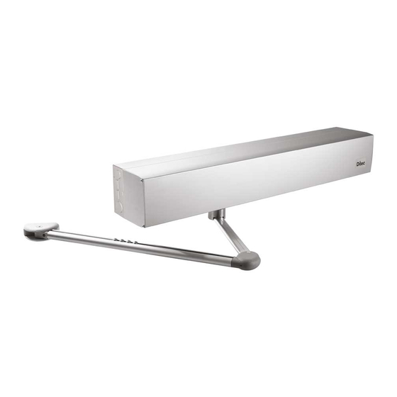
- Page 1 IP2159EN Ditec DAB105 Technical Manual Swing doors (translation of the original instructions) www.entrematic.com...
-
Page 2: Table Of Contents
Contents Subject Page General safety precautions General safety precautions for the user Declaration of incorporation of partly completed machinery Technical specifications Standard installation Dimensions Main components Installation 7.1 Preliminary checks 7.2 General information 7.3 Installation examples 7.4 Removing the cover Automation with articulated arm DAB805PSA 8.1 Automation preparation and fastening 8.2 Fixing the arm... -
Page 3: General Safety Precautions
1. General safety precautions This installation manual is intended for qualified personnel only. Installation, electrical connections and adjustments must be performed in accordance with Good Working Methods and in compliance with the present standards. Read the instructions carefully before installing the product. Incorrect installation could be dangerous. -
Page 4: General Safety Precautions For The User
2. General safety precautions for the user These precautions are an integral and essential part of the product and must be supplied to the user. Read them carefully since they contain important information on safe installation, use and maintenance. These instructions must be kept and forwarded to all possible future users of the system. This product must only be used for the specific purpose for which it was designed. -
Page 5: Declaration Of Incorporation Of Partly Completed Machinery
Entrematic Group AB Lodjursgatan 10 SE-261 44 Landskrona Sweden declare under our responsibility that the following types of equipment: Ditec DAB105 comply with the following directives: 2014/30/EU Electromagnetic Compatibility Directive (EMCD) 2006/42/EC Machinery Directive (MD) for the following essential health and safety requirements: 1.1.2, 1.1.3, 1.2.1, 1.2.3, 1.2.4, 1.2.6, 1.3.2, 1.3.4, 1.5.1, 1.5.2, 1.5.3, 1.5.8, 1.5.9, 1.5.10, 1.5.11, 1.6.3, 1.7.3, 1.7.4... - Page 6 Revisions The following pages have been revised: Page Revision 2016-05-05 → 2017-06-12 DAB805PLA arm inertia data item "Fixing requisites" paragraph added Modified dimensions for Y arm extension distance Slide guide dimension GND-OPD description DIP1 description Description of alarm 1 Description of the battery functions Trimmer description Paragraph for advanced settings (increased thrust force on closure / management of electric lock power supply)
-
Page 7: Technical Specifications
3. Technical specifications DAB105 Power 100-240V~ +10/-15% 50/60 Hz Consumption max. 75W Power supply for accessories 400 mA max. Power supply fuse F1-F2 2xT6.3A 250 V Opening time min. 3s / 0°-80° max. 6s / 0°-80° Closing time min. 3s / 90°-10° max. -
Page 8: Standard Installation
4. Standard installation Ref. Code Description DAB105 Electro-mechanical actuator Control panel DAB805PSA-PSAF Articulated movement arm (DAB805PSAF for applications on fire barriers) DAB805PLA Sliding movement arm DAB805PLAT Movement arm with three levers DAB805PLAB Sliding movement arm (break-out/anti-panic) Opening sensor COM400MHB Function selector switch COM400MKB Command button Connect the power supply to a type-approved omnipolar switch, with a contact opening distance of at... -
Page 9: Dimensions
5. Dimensions Ø18 (6x) 23 (2x) Ø7 (6x) Ø7 (6x) 1 11 / 16" 8 1 / 4" 210 mm 30 mm... -
Page 10: Main Components
6. Main components Ref. Code Description Base plate Gearmotor DAB105CU Control panel Power End stop Upper head Lower head Casing DAB905ESE Safety and pulse extension card (optional) DAB905ESA Extension card for safety functions (optional) Cable fastener Cable transit slits DAB905BAT Battery kit Encoder ON/OFF/HOLD OPEN switch... -
Page 11: Installation
7. Installation The given operating and performance features can only be guaranteed with the use of DITEC Entrematic accessories and safety devices. Unless otherwise specified, all measurements are expressed in mm. 7.1 Preliminary checks Check the stability and weight of the door wing. Make sure it moves smoothly, without any friction (reinforce the frame if necessary). Any “door closers”... -
Page 12: Installation Examples
7.3 Installation examples The DAB105 automation for swing doors can be installed on one swing door, on two swing doors, or on two swing doors with a double exit. DAB805CMP DAB805CMP DAB805SE2 7.4 Removing the casing Remove the casing [8] by loosening the screw [Z]. NB: the product label is in the position shown in the figure below. -
Page 13: Automation With Articulated Arm Dab805Psa
8. Automation with articulated arm DAB805PSA Use the articulated arm for doors that open outwards (as seen from the automation side). Before fixing the base plate [1], make holes for the cables to pass through. Shaft extension ~400 DAB805SE2 Ø 16 DAB805SE5 DAB805SE7 OPENING... - Page 14 6 mm • Fix the automation in place using the screws [A]; tighten them firmly and evenly. • Move the gearmotor sideways by loosening the 4 screws [B], so the base plate can be fixed in place. • Fix the base plate with the screws [A]. 6 mm •...
- Page 15 Apertura a destra Right-hand opening • Prepare the set-up for fixing the automation to the wall, respecting the measurements shown in the figures above (with reference to the hinge axis). • Drill a hole in the door wing, in line with the fixing for the articulated arm. •...
-
Page 16: Fixing The Arm
8.2 Fixing the arm NB: open the door slightly and tighten the screw of the arm support seat [A] at 16 Nm (as shown in the figure). If a torque wrench is not available, use a hexagon wrench of the type shown in the 90°... -
Page 17: Automation With Articulated Arm Dab805Psaf
9. Automation with articulated arm DAB805PSAF (for applications on fire barriers) Before fixing the base plate [1], make holes for the cables to pass through. Shaft extension DAB805SE5F Ø 16 Arm expansion 0-100 100-215 DAB805TFL 215-305 DAB805TFS DAB805TKJ OPENING 9.1 Automation preparation and fastening Left-hand opening Apertura a sinistra •... - Page 18 6 mm • Fix the automation in place using the screws [A]; tighten them firmly and evenly. • Move the gearmotor sideways by loosening the 4 screws [B], so the base plate can be fixed in place. • Fix the base plate with the screws [A]. 6 mm •...
- Page 19 Apertura a destra Right-hand opening • Prepare the set-up for fixing the automation to the wall, respecting the measurements shown in the figures above (with reference to the hinge axis). • Drill a hole in the door wing, in line with the fixing for the articulated arm. •...
-
Page 20: Fixing The Arm
9.2 Fixing the arm Kit prolungamento braccio Arm extension kit DAB805TFL 90° DAB805TFS DAB805TKJ 25 Nm • Move the door manually to check it opens and closes correctly, without any friction. • With the door closed, fix the arm to the arm support [A] on the automation. •... -
Page 21: Automation With Sliding Arm Dab805Pla
10. Automation with sliding arm DAB805PLA Use the sliding arm for doors that open inwards (as seen from the automation side). Before fixing the base plate [1], make holes for the cables to pass through. Ø 16 Shaft extension DAB805SE2 DAB805SE5 DAB805SE7 OPENING... - Page 22 1 8 0 ° • Fix the automation using the screws [A], tightening them firmly. • Loosen the screws [B] that hold the motor in place. Remove the motor. Fix the base plate with the 2 screws [A]. • Rotate the motor 180°, as shown in the figure. 6 mm B x4 •...
- Page 23 Apertura a destra Right-hand opening • Prepare the set-up for fixing the automation to the wall, respecting the measurements shown in the figures above (with reference to the hinge axis). • Drill a hole in the door wing, in line with the fixing for the sliding arm. •...
- Page 24 1 8 0 ° • Loosen the screws [B] that hold the motor in place. Remove the motor. Fix the base plate with the 2 screws [A]. • Rotate the motor 180°, as shown in the figure. 6 mm B x4 2 1 0 •...
-
Page 25: Fixing The Sliding Arm
10.2 Fixing the sliding arm min 700 4 mm 16 Nm NB: open the door slightly and tighten the screw of the arm support seat [A] at 16 Nm (as shown in the figure). If a torque wrench is not available, use a hexagon wrench of the type shown in the figure, gripping it on the long side and tightening very firmly. -
Page 26: Fixing The Door Stop
10.3 Fixing the door stop Left-hand opening Right-hand opening Apertura a sinistra Apertura a destra 180° 180° The following operations must be carried out with the arm installed and the door closed. In the case of installations with a sliding arm, proceed as follows: •... -
Page 27: Connecting To The Electricity Supply
11. Connecting to the electricity supply Before connecting the power supply, make sure the plate data correspond to that of the mains power supply. An omnipolar disconnection switch with a contact opening distance of at least 3 mm must be fitted on the mains supply. Check there is an adequate residual current circuit breaker and overcurrent cut-out upstream of the electrical system. -
Page 28: Starting Up The Door
12. Starting up the door Place the door in the closed position. Rotate the SPTE trimmer on the control panel to 0° (if it is not already in this position). SPTE 0° Turn on the power supply. Gradually rotating the SPTE trimmer clockwise, the door opens electrically. Slowly bring it to the required open position, plus about 15 mm. -
Page 29: Dab105Cu Electrical Connections
13. Electrical connections DAB105CU SINCRONIZZAZIONE ANTE DOPPIE SYNCHRONISATION OF DOUBLE DOOR WINGS ON/OFF/HOLD OPEN ON/OFF/HOLD OPEN 24 V LOUT NON USARE DO NOT USE Rilevamento di presenza / pedana a pavimento Motion sensor / mat safety Opening (controlled from ON/OFF Apertura (controllata da ON/OFF XIMP HOLD OPEN) -
Page 30: Outputs And Accessories
Contact Function / Accessory Description Automatic self-learning. When the door is started up, and on every spring tensioning variation, CLTQ trimmer variation, replacement of the extension units (DAB905ESE-DAB905ESA) or replacement of the electric lock / electic strike, it is necessary to perform an automatic self-learning operation. -
Page 31: Adjustments
13.3. Adjustments Trimmer Trimmer Description SPTE Door start-up The SPTE trimmer is used to make adjustments for the acquisition of the opening/closing stops when the door starts up. Spring tension adjustment The spring pre-tensioning is factory-set at 210°. The maximum pre-tensioning of the spring is 210°. A greater tension could damage the spring or overheat the motor. - Page 32 Dip-switches Description DIP1 - PAG Push & Go Disabled Enabled The manual pushing of the door activates an automatic opening operation. When the door is closed, a closure thrust is main- tained by the motor or the spring. Push and Go is not active in program se- lector setting DOOR CLOSED.
-
Page 33: Pre-Configured Parameters
14. Pre-configured parameters The DAB105 automation has 10 groups of pre-configured system-loaded parameters. The group of parameters set in the factory corresponds to number 1. To modify the group of parameters: 1. Disconnect the batteries (if installed). 2. Disconnect the mains power supply. 3. -
Page 34: Door Requisites For Low Energy Use
15. Door requisites for Low Energy use The DAB105 automation is factory supplied with the Low Energy setting enabled. If necessary, adjust the OPSP and CLSP trimmers so that the opening and closing times are the same or longer than those indicated in the table in accordance with EN16005:2012 and ANSI 156.19 (the information in brackets refers to DIN 18650-2). -
Page 35: Example Of An Application With A Standard Automation
16. Example of an application with a standard control panel Double wings connection DAB105 ON/OFF/HOLD OPEN ON/OFF/HOLD OPEN PASS24 (XIMP) PASS24 (XIMP) -
Page 36: Ese Extension Unit Dab905Ese (Optional)
17. Extension unit DAB905ESE (optional) There is a command extension card for managing the electric lock / electric strike, function selector, batteries, key selector switch and night-time closure. BATTERIES BATTERIE Torx T10 Torx T10 DAB905ESA +24 V DC (optional) (optional) OPEN EXIT 5 mm nut driver... - Page 37 Contact Function - Accessory Description EMERGENCY CLOSURE The closure of the contact activates an emergency closure operation. This command is ac- tive in every situation, and has priority over every other command. GND-KILL (FIRE BARRIERS) When the contact has reopened (with JUMPER J=ON), the door resumes operating as set by the selector.
-
Page 38: Outputs And Accessories
17.2 Outputs and accessories Output Description Output for the power supply to the accessories 24V 400 mA max. 3 ... NB: the maximum absorption of 400 mA corresponds to the sum of all the accessories installed. Output for connecting an electric lock / electric strike. Select the type of electric lock / electric strike using DIP1. -
Page 39: Advanced Settings Available On The Control Panel Version Indicated, Or Subsequent Versions
17.4 Advanced settings available on the control panel version indicated, or subse- quent versions DAB105CU 0501123456 Increased thrust force on closure when an electric lock is fitted 1. Disconnect batteries if any. 2. Disconnect the mains. 3. Press the LEARN BUTTON (LRN) and keep it depressed. 4. -
Page 40: Dab905Esa Extension Unit
18. Extension unit DAB905ESA (optional) There is a command extension card for managing motion sensors, alarm indications and door status. Torx T10 Torx T10 SAFETY EXCLUSION LED ESCLUSIONE DAB905ESA (optional) (optional) SICUREZZA 24V output 1 A Uscita 24 V 1 A 5 mm nut driver 5 mm nut driver NON USARE... -
Page 41: Outputs And Accessories
18.2 Outputs and accessories Output Description Output for the power supply to the accessories 24V 400 mA max. 1 ... NB: the maximum absorption of 400 mA corresponds to the sum of all the accessories installed. Connect a self-checking safety sensor on the door wing. Connect the closing side sensor to terminals 1-2 (GND-PIMP). -
Page 42: Adjustments
18.3. Adjustments Trimmer Trimmer Description Adjustment of the opening safety exclusion, from 45° to 90°. During the door opening phase, this excludes the functioning of the safety device installed on the door wing, so that the wall is not detected. When the safety device is excluded, the LED lights up. -
Page 43: Example Of An Application With Optional Extension Units
19. Example of an application with optional extension units Battery Battery Error indication or door open (DAB905ESA) Error indication or door open (DAB905ESA) (DAB905ESE) (DAB905ESE) DAB105 PASS24 (OIMP - DAB905ESE) PASS24 (IIMP) (DAB905ESA) - Page 44 20. Parallel automations (DAB905SYN) SORMONTO OVERLAP SFIORAMENTO SENZA SFIORAMENTO DOPPIA USCITA DOUBLE EXIT SKIM WITHOUT SKIM Connect the two automations to the plug on the control panel, using the synchronisation cable (DAB905SYN). Depending on the type of installation, cut the jumpers on the MASTER or SLAVE cable, as shown in the table: The MASTER automation is the one that opens first.
- Page 45 20.2 Example of installation of parallel doors (DAB905SYN) INNER INNER FUNCTION FUNCTION OPEN SENSOR OPEN SENSOR SELECTOR SELECTOR SAFETY SAFETY SAFETY SAFETY SENSOR SENSOR SENSOR SENSOR SLAVE MASTER OUTER OUTER OPEN SENSOR OPEN SENSOR SLAVE MASTER (see applications chapter 21) DAB905SYN (see applications chapter 21) INNER OPEN SENSOR INNER OPEN SENSOR...
- Page 46 20.3 Interlocked automations (DAB905SYN) DOOR B DOOR A DOOR A DOOR B MAGNET MAGNET SWITCH SWITCH +24 V DC OPEN EXIT MASTER SLAVE DOOR B DOOR B MAGNET MAGNET DOOR B DOOR B SWITCH KRST SWITCH KILL OIMP DAB905ESE DOOR B DOOR B DOOR A DOOR A...
-
Page 47: Electrical Start-Up
21. Electrical start-up Before performing any type of operation, make sure that the automation is turned off and the batteries are discon- nected. The trimmers can only be adjusted with the automation idle. 1. Connect the motor and encoder cables to the DAB105CU control panel. 2. -
Page 48: Troubleshooting
23. Troubleshooting Problem Possible cause Solution / Explanation The door does not open a) The motor does not start The function selector is set on OFF Change the function selector setting There is no mains power supply Check the mains power supply The command unit does not work Check the connections of the command ac- cessories... -
Page 49: Signs
24. Signs 40 mm Make sure the signs are in good condition, and attach them. Obligatory indicates that this sign is required by the European directives and equivalent national legislation outside the EEC. Ref. Description Product label. Obligatory. DAB105 ART. NO. TYPE YEAR+WEEK XXXXXXX... - Page 50 Entrematic Group AB Lodjursgatan 10 SE-261 44, Landskrona Sweden www.entrematic.com...
Need help?
Do you have a question about the Ditec DAB105 and is the answer not in the manual?
Questions and answers