Table of Contents
Advertisement
Quick Links
Side
B
Side
Side
A
B
JAPANESE
ENGLISH
FX
-30M/E-2AD
3S
HARDWARE MANUAL
Manual Number
JY997D51701
Revision
E
Date
December 2017
This manual describes the part names, dimensions, mounting, cabling and
specifications of the product. Before use, read this manual and the manuals of
all relevant products fully to acquire proficiency in handling and operating the
product. Make sure to learn all the product information, safety information, and
precautions.
Store this manual in a safe place so that it can be taken out and read whenever
necessary. Always forward it to the end user.
Registration: Phillips is a registered trademark of Phillips Screw Company.
The company and product names described in this manual are registered
trademarks or the trademarks of their respective companies.
Effective December 2017
Specifications are subject to change without notice.
©
2013 MITSUBISHI ELECTRIC CORPORATION
Safety Precaution
(Read these precautions before use.)
If the equipment is used in a manner not specified by the manufacturer, the
protection provided by the equipment may be impaired.
This manual classifies the safety precautions into two categories:
and
.
Indicates that incorrect handling may cause hazardous
conditions, resulting in death or severe injury.
Indicates that incorrect handling may cause hazardous
conditions, resulting in medium or slight personal injury
or physical damage.
Depending on the circumstances, procedures indicated by
also cause severe injury.
It is important to follow all precautions for personal safety.
STARTUP AND MAINTENANCE
PRECAUTIONS
• Do not touch any terminal while the PLC's power is on.
Doing so may cause electric shock or malfunctions.
• Before cleaning or retightening terminals, cut off all phases of the power
supply externally. Failure to do so may cause electric shock.
• Before modifying or disrupting the program in operation or running the
PLC, carefully read through this manual and the associated manuals and
ensure the safety of the operation.
An operation error may damage the machinery or cause accidents.
STARTUP AND MAINTENANCE
PRECAUTIONS
• Turn off the power to the PLC before attaching or detaching the memory
cassette. If the memory cassette is attached or detached while the PLC's
power is on, the data in the memory may be destroyed, or the memory
cassette may be damaged.
• Do not disassemble or modify the PLC.
Doing so may cause fire, equipment failures, or malfunctions.
For repair, contact your local Mitsubishi Electric representative.
• Turn off the power to the PLC before connecting or disconnecting any
connection cable.
Failure to do so may cause equipment failures or malfunctions.
JY997D51701E
STARTUP AND MAINTENANCE
PRECAUTIONS
• Turn off the power to the PLC before attaching or detaching the following
devices. Failure to do so may cause equipment failures or malfunctions.
- Peripheral devices, display module, expansion boards, special
adapters and memory cassette
• Do not use the chemicals for cleaning.
• If there is the possibility of touching the PLC inside a control panel in
maintenance, make sure to discharge to avoid the influence of static
electricity.
DISPOSAL PRECAUTIONS
• Please contact a certified electronic waste disposal company for the
environmentally safe recycling and disposal of your device.
TRANSPORTATION AND
STORAGE PRECAUTIONS
• The PLC is a precision instrument. During transportation, avoid impacts
larger than those specified in section 3.1 by using dedicated packaging
boxes and shock-absorbing palettes.
Failure to do so may cause failures in the PLC.
After transportation, verify operation of the PLC and check for damage of
the mounting part, etc.
Associated manuals
How to obtain manuals
For the necessary product manuals or documents, consult with your local
Mitsubishi Electric representative.
Associated manuals
FX
-30M/E-2AD comes with this document (hardware manual).
3S
For a detailed explanation of the FX
Series hardware and information on
3S
instructions for PLC programming, refer to the relevant documents.
Specifications not described in this manual are same as FX
refer to the following manual.
→ Refer to FX
Series User's Manual - Hardware Edition.
3S
Manual name
Manual No.
Explains FX
JY997D48601
FX
Series User's Manual
specification details for I/O,
3S
MODEL CODE:
- Hardware Edition
wiring, installation, and
09R535
maintenance.
FX
/FX
/FX
/FX
/
Describes PLC programming
3S
3G
3GC
3U
JY997D16601
FX
Series Programming
for basic/applied instructions
3UC
MODEL CODE:
Manual - Basic & Applied
STL/SFC programming and
09R517
Instruction Edition
devices.
Programming methods,
MELSEC-Q/L/F Structured
SH-080782
specifications, functions, etc.
Programming Manual
MODEL CODE:
required to create structured
(Fundamentals)
13JW06
may
programs.
FXCPU Structured
JY997D26001
Devices, parameters, etc.
Programming Manual
MODEL CODE:
provided in structured
[Device & Common]
09R925
projects of GX Works2.
FXCPU Structured
JY997D34701
Sequence instructions
Programming Manual
MODEL CODE:
provided in structured
[Basic & Applied Instruction]
09R926
projects of GX Works2.
FXCPU Structured
JY997D34801
Application functions
Programming Manual
MODEL CODE:
provided in structured
[Application Functions]
09R927
projects of GX Works2.
Explains N:N link, parallel
FX Series User's Manual
JY997D16901
link, computer link, no
- Data Communication
MODEL CODE:
protocol communication by
Edition
09R715
RS instructions/FX
Describes specifications for
FX
/FX
/FX
/FX
/
JY997D16701
analog control and
3S
3G
3GC
3U
FX
3UC
Series User's Manual
MODEL CODE:
programming methods for
- Analog Control Edition
09R619
FX
3S
FX
3UC
Explains the specifications
FX
/FX
/FX
/FX
/
JY997D16801
for positioning control of
3S
3G
3GC
3U
FX
Series User's Manual
MODEL CODE:
FX
3UC
3S
- Positioning Control Edition
09R620
FX
3UC
programming procedures.
Certification of UL, cUL standards
Please consult with Mitsubishi Electric for information on UL, cUL standard
practices and the corresponding types of equipment.
Compliance with EC directive (CE Marking)
This product complies with EC directive, however, this document does not
guarantee that a mechanical system including this product will comply with EC
directive.
Compliance to EMC directive and LVD directive of the entire mechanical
system should be checked by the user/manufacturer. For more details please
contact the local Mitsubishi Electric sales site.
Caution for compliance with EC Directive
• Please use the FX
programmable controllers while installed in conductive
3S
shielded control panels under a general industrial environment.
• Programmable controllers are open-type devices that must be installed and
used within conductive control panels. Please secure the control box lid to
the control box (for conduction). Installation within a control box greatly
affects the safety of the system and aids in shielding noise from the
programmable controller.
• For the control panel, use the product having sufficient strength, fire
protectiveness and shielding property to an installation environment.
• 24 V DC of the power supply must be supplied from the circuit double/
reinforced insulated from the main power supply (MAINS).
Caution for compliance with the LVD directive (EN61010-2-201:2013)
• To an external connection port other than AC power supply terminal and AC
input/output terminal, connect the circuit separated from a dangerous
voltage by a double/reinforced insulation.
• Between the commons having the adjacent relay output terminals, if an
external power supply is higher than 120 V AC, the insulation is basic.
Therefore, when using 120 V AC or higher external power supply and 30 V
DC/AC or lower external power supply between the adjacent commons, do
not handle 30 V DC/AC or lower external power supply as a touchable part,
(When handling 30 V DC/AC or lower external power supply as a touchable
part, add a basic insulation.)
• Do not wire two or more crimp terminals to one terminal. (If the wiring with
PLC. For details,
3S
two or more wires is needed, take an appropriate action such as adding an
external terminal.)
• For crimp terminals to be used for the wiring applied with 30 V AC or higher,
Description
use the products with insulating sleeves.
• Cutoff device such as a breaker or a circuit protector should be installed in
3S
Series PLC
accordance with the following precautions.
- Use EN60947-1 or EN60947-3 standards.
- Use CP30-BA 2P 1-MD 0.5A or the cutoff device having the cutoff performance
equivalent to CP30-BA 2P 1-MD 0.5A.
- Place the cutoff device so that it can be operated easily.
- Specify that the cutoff device is for this equipment.
*1 For the time of compliance with the LVD directive (EN61010-2-201:2013),
refer to FX
3S
Series User's Manual - Hardware Edition.
Analog input/output
The analog input/output have been found to be compliant to the European
standards in the aforesaid manual and directive. However, for the very best
performance from what are in fact delicate measuring and controlled output
devices, Mitsubishi Electric would like to make the following points.
As analog devices are sensitive by nature, their use should be considered
carefully. For users of proprietary cables (integral with sensors or actuators),
these users should follow those manufacturers' installation requirements.
Mitsubishi Electric recommends that shielded cables be used. If NO other EMC
protection is provided, users may experience temporary loss or accuracy
between +10 %/-10 % in very heavy industrial areas.
However, Mitsubishi Electric suggests that adequate EMC precautions be
followed for the users complete control system.
- Sensitive analog cables should not be laid in the same trunking or cable
conduit as high voltage cabling. Where possible, users should run analog
cables separately.
- Good cable shielding should be used. When terminating the shield at
Earth, ensure that no earth loops are accidentally created.
- When reading analog values, EMC accuracy can be improved by
averaging the readings. This can be achieved either through functions on
-232IF.
2N
the analog products or through a user's program in the FX
main unit.
Incorporated Items
/FX
/FX
/FX
/
3G
3GC
3U
Series PLC.
Check if the following product and items are included in the package:
/FX
/FX
/FX
/
3G
3GC
3U
Product
Series and
FX
-30MR/ES-2AD,
3S
FX
-30MT/ES-2AD,
Dust proof protection sheet
3S
FX
3S
-30MT/ESS-2AD
Manuals [Japanese/English]
1. Feature
FX
-30M/E-2AD is a product based on FX
3S
input in place of variable analog potentiometers.
(Refer to the following figure)
Specifications other than the built-in analog input are the same as FX
For details, refer to FX
For details on the built-in analog input, refer to Chapter 6.
Variable analog potentiometer
2. Outline
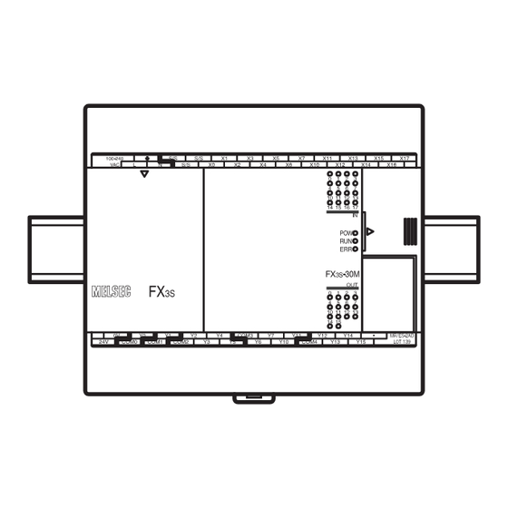
2.1 Part names
[3]
*1
[2]
[1]
No.
[1]
Top cover
Terminal names
[2]
shows a function grounding terminal.
[3]
Terminal block covers
[4]
Input display LEDs (red)
[5]
Peripheral device connecting connector cover
Operation status display LEDs
POW
Green
[6]
RUN
Green
Red
ERR
Red
[7]
Output display LEDs (red)
[8]
The year and month of production
[9]
Model name (abbreviation)
[10]
DIN rail mounting hooks
When the top covers are open
[8]
Series PLC
3S
[9]
No.
Included Items
[1]
Optional equipment connector
1 unit
[2]
Power supply terminal, Input (X) terminals
1 sheet
[3]
Analog input terminal block
[4]
RUN/STOP switch
1 manual
PLC, with built-in analog
3S
PLC.
3S
3S
Series User's Manual - Hardware Edition.
Analog input terminal block
[4]
[5]
[6]
[7]
[10]
[9]
[8]
Name
On while power is on the PLC.
On while the PLC is running.
Flashing when a program error occurs.
Lights when a CPU error occurs.
[1]
[2]
[3]
[4]
[5]
[6]
[7]
[8]
Name
Advertisement
Table of Contents

Related Manuals for Mitsubishi Electric FX3S-30MT/ES-2AD


Summary of Contents for Mitsubishi Electric FX3S-30MT/ES-2AD
- Page 1 [Device & Common] 09R925 projects of GX Works2. STARTUP AND MAINTENANCE Mitsubishi Electric recommends that shielded cables be used. If NO other EMC Model name (abbreviation) PRECAUTIONS protection is provided, users may experience temporary loss or accuracy FXCPU Structured...
- Page 2 *1 The criterion is shown in IEC61131-2. 3.3 Procedures for installing to DIN rail Name INSTALLATION *2 Dielectric withstand voltage and insulation resistance are shown in the The products can be installed on a DIN46277 rail [35 mm (1.38”) wide]. PRECAUTIONS Peripheral device connecting connector (USB) following table.
- Page 3 4.2.2 Example of external wiring 4.4.2 Examples of input wiring Notes 4. Power supply/input/output specifications and 100 to 240 V AC power is supplied to the main unit. 1. Sink input type 2. Source input type • Input/output wiring 50 to 100 m (164’1” to 328’1”) long will cause almost 100 to 240 V AC examples of external wiring Fuse...
- Page 4 - ± 2.0 % (± 200 mV) for 10 V full scale nor does it confer any patent licenses. Mitsubishi Electric Corporation cannot be 2. External wiring of source output type - The disposal size of the cable end should follow the dimensions (when ambient temperature is 0 to 55 °C)
Need help?
Do you have a question about the FX3S-30MT/ES-2AD and is the answer not in the manual?
Questions and answers