Table of Contents
Advertisement
nordictrack.com
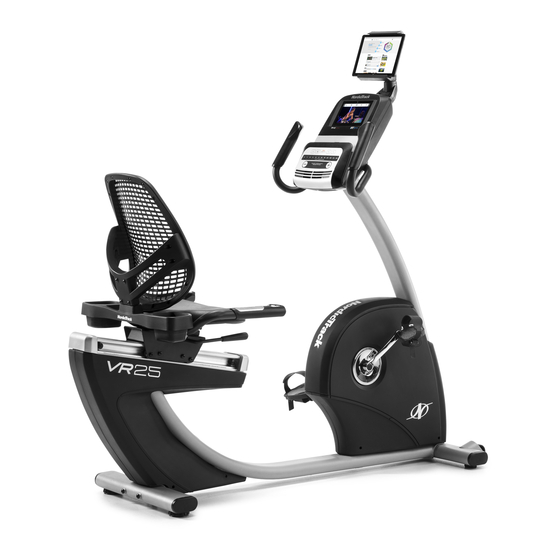
Model No. NTEX89918.0
Serial No.
Write the serial number in the
space above for reference.
Serial Number
Decal
ACTIVATE YOUR
WARRANTY
To register your product and
activate your warranty today,
go to my.nordictrack.com.
CUSTOMER CARE
For service at any time, go to
nordictrackservice.com.
Or call 1-800-TO-BE-FIT
(1-800-862-3348)
Mon.–Fri. 6 a.m.–6 p.m. MT
Sat. 8 a.m.–12 p.m. MT
Please do not contact the store.
CAUTION
Read all precautions and instruc-
tions in this manual before using
this equipment. Keep this manual
for future reference.
USER'S MANUAL
Advertisement
Table of Contents

Related Manuals for NordicTrack VR25


Summary of Contents for NordicTrack VR25
- Page 1 Serial Number Decal ACTIVATE YOUR WARRANTY To register your product and activate your warranty today, go to my.nordictrack.com. CUSTOMER CARE For service at any time, go to nordictrackservice.com. Or call 1-800-TO-BE-FIT (1-800-862-3348) Mon.–Fri. 6 a.m.–6 p.m. MT Sat.
-
Page 2: Table Of Contents
Apply the decal in the location shown. Note: The decal(s) may not be shown at actual size. NORDICTRACK and IFIT are registered trademarks of ICON Health & Fitness, Inc. The BLUETOOTH word ® mark and logos are registered trademarks of Bluetooth SIG, Inc. and are used under license. Google Maps is a trademark of Google Inc. -
Page 3: Important Precautions
IMPORTANT PRECAUTIONS WARNING: To reduce the risk of serious injury, read all important precautions and instructions in this manual and all warnings on your exercise bike before using your exercise bike. ICON assumes no responsibility for personal injury or property damage sustained by or through the use of this product. - Page 4 STANDARD SERVICE PLANS...
-
Page 5: Before You Begin
BEFORE YOU BEGIN Thank you for selecting the revolutionary reading this manual, please see the front cover of this NORDICTRACK VR 25 exercise bike. Cycling is an manual. To help us assist you, note the product model ® effective exercise for increasing cardiovascular fitness, number and serial number before contacting us. -
Page 6: Part Identification Chart
PART IDENTIFICATION CHART Use the drawings below to identify the small parts needed for assembly. The number in parentheses below each drawing is the key number of the part, from the PART LIST near the end of this manual. The number following the key number is the quantity needed for assembly. -
Page 7: Assembly
“R” or “Right.” wrenches. To avoid damaging parts, do not use power tools. • To identify small parts, see page 6. 1. Go to my.nordictrack.com on your computer and register your product. • documents your ownership • activates your warranty •... -
Page 8: The Wires
3. Set a sturdy piece of packing material under the front of the Frame (1). Have a second person hold the Frame to prevent it from tipping while you complete this step. Orient the Front Stabilizer (15) as shown. Attach the Front Stabilizer to the Frame (1) with two M10 x 122mm Screws (65). - Page 9 5. Tip: Avoid pinching the wires. Slide the Upright (2) onto the Frame (1). Attach the Upright (2) with four M10 x 62mm Screws (70); start all the Screws, and then tighten them. Avoid pinching the wires 6. Press the mount on the Front Shield (58) into the Frame (1).
-
Page 10: Console To The Main Wire (43) And The Frame
7. Orient the Upright Cover (57) as shown. Hold the Upright Cover near the Upright (2), and insert the wire tie (A) and the wires (B) upward through the Upright Cover. Then, slide the Upright Cover (57) onto the Upright (2). 8. - Page 11 10. Tip: Avoid pinching the wires. Attach the Console (4) to the Handlebar (7) with four M4 x 16mm Screws (77); start all the Screws, and then tighten them. Avoid pinching the wires 11. Attach the Upright Cover (57) to the Handlebar (7) with two M4 x 16mm Screws (77).
- Page 12 13. Insert the Rail Rod (60) into the Rail (5), and tighten a Rod Cap (62) onto each end of the Rail Rod. 14. Press the mounts on the Rear Rail Cover (90) into the Rail (5). Then, plug the wire (C) on the seat assembly fully into the Frame Pulse Receptacle (42) on the left side of the exercise bike.
- Page 13 15. Identify the Right Pedal (21). Using an adjustable wrench, firmly tighten the Right Pedal (21) clockwise into the Right Crank Arm (23). Firmly tighten the Left Pedal (not shown) counterclockwise into the Left Crank Arm (not shown). IMPORTANT: You must turn the Left Pedal counterclockwise to attach it.
- Page 14 17. Then, plug the Power Adapter (51) into the receptacle on the frame of the exercise bike. Note: To plug the Power Adapter (51) into an outlet, see HOW TO PLUG IN THE POWER ADAPTER on page 16. 18. After the exercise bike is assembled, inspect it to make sure that it is assembled correctly and that it functions properly.
-
Page 15: The Chest Heart Rate Monitor
THE CHEST HEART RATE MONITOR HOW TO PUT ON THE HEART RATE MONITOR • Store the heart rate monitor in a warm, dry place. Do not store the heart rate monitor in a plastic bag or If the heart rate monitor looks like the one shown in other container that may trap moisture. -
Page 16: How To Use The Exercise Bike
HOW TO USE THE EXERCISE BIKE HOW TO PLUG IN THE POWER ADAPTER HOW TO ADJUST THE PEDAL STRAPS IMPORTANT: If the exercise bike has been exposed To adjust the pedal to cold temperatures, allow it to warm to room straps (C), first pull temperature before you plug in the power adapter. - Page 17 CONSOLE DIAGRAM FEATURES OF THE CONSOLE When you use the manual mode of the console, you can change the resistance of the pedals with the touch The advanced console offers an array of features of a button. designed to make your workouts more effective and enjoyable.
- Page 18 HOW TO TURN ON THE CONSOLE HOW TO USE THE TOUCH SCREEN The included power adapter must be used to oper- The console features a tablet with a full-color touch ate the exercise bike. See HOW TO PLUG IN THE screen.
- Page 19 HOW TO SET UP THE CONSOLE To use the manual mode, see this page. To use a map workout or an onboard workout, see page Before you use the exercise bike for the first time, set 21. To create a draw-your-own-map workout, see page 23.
- Page 20 4. Follow your progress. If there are sheets of plastic on the metal contacts (A) on the handgrip heart rate moni- The console offers several display modes. The tor, remove the plastic. To measure your heart display mode that you select will determine which rate, hold the handgrip heart rate monitor with your palms resting against the contacts.
- Page 21 HOW TO USE A MAP WORKOUT OR AN ONBOARD symbol). You must be logged into your iFit account WORKOUT to save a featured map workout (see step 3 on page 19). 1. Touch the screen or press any button on the console to turn on the console.
- Page 22 If the resistance level is too high or too low, you can publish your results using one of the options on can manually override the setting by pressing the the screen. Then, touch Finish to return to the main Resistance buttons. If you press a Resistance menu.
- Page 23 HOW TO CREATE A DRAW-YOUR-OWN-MAP If you make a mistake, touch Undo on the left side WORKOUT of the screen. 1. Touch the screen or press any button on the The screen will display the elevation and distance console to turn on the console. statistics for your workout.
- Page 24 HOW TO USE AN IFIT WORKOUT 4. Select an iFit workout that you have previously added to your schedule on iFit.com. To use an iFit workout, the console must be connected IMPORTANT: Before iFit workouts will load, you to a wireless network (see HOW TO CONNECT TO A must add them to your schedule on iFit.com WIRELESS NETWORK on page 26).
- Page 25 HOW TO CHANGE CONSOLE SETTINGS 3. View the console tour presentation. IMPORTANT: Some of the settings and features To view a tour presentation that will guide you described may not be enabled. Occasionally, a through the features of the console, touch How It firmware update may cause your console to function Works.
- Page 26 HOW TO CONNECT TO A WIRELESS NETWORK Note: You must have your own wireless network and an 802.11b/g/n router with SSID broadcast To use iFit workouts and to use several other features enabled (hidden networks are not supported). of the console, the console must be connected to a wireless network.
-
Page 27: Fcc Information
HOW TO USE THE SOUND SYSTEM Next, place or hold your device near the console. Then, pair your device to the console as follows: Press and To play music or audio books through the console hold the Bluetooth button on the console for 3 seconds; sound system while you exercise, plug a 3.5 mm male the console will enter pairing mode. -
Page 28: Maintenance And Troubleshooting
MAINTENANCE AND TROUBLESHOOTING MAINTENANCE HOW TO ADJUST THE REED SWITCH Regular maintenance is important for optimal If the console does not display correct feedback, the performance and to reduce wear. Inspect and properly reed switch should be adjusted. tighten all parts each time the exercise bike is used. To adjust the reed switch, first unplug the power Replace any worn parts immediately. - Page 29 HOW TO ADJUST THE DRIVE BELT Next, loosen the M6 x 20mm Hex Screw (84). Then, tighten the M10 x 50mm Hex Screw (83) until the Drive If the pedals slip while you are pedaling, even while the Belt (47) is tight. When the Drive Belt is tight, tighten resistance is adjusted to the highest setting, the drive the M6 x 20mm Hex Screw.
-
Page 30: Exercise Guidelines
EXERCISE GUIDELINES Burning Fat—To burn fat effectively, you must exer- WARNING: cise at a low intensity level for a sustained period of Before beginning this time. During the first few minutes of exercise, your or any exercise program, consult your physi- body uses carbohydrate calories for energy. - Page 31 SUGGESTED STRETCHES The correct form for several basic stretches is shown at the right. Move slowly as you stretch; never bounce. 1. Toe Touch Stretch Stand with your knees bent slightly and slowly bend forward from your hips. Allow your back and shoulders to relax as you reach down toward your toes as far as possible.
-
Page 32: Part List
PART LIST Model No. NTEX89918.0 R0118A Key No. Qty. Description Key No. Qty. Description Frame Reed Switch/Wire Upright Drive Belt Foot Stabilizer Cap Console Left Handlebar Grip Rail Flange Screw Adjustment Bar Power Adapter Handlebar Shield Disc Backrest Tablet Holder Seat Tablet Holder Screw Seat Handlebar/Wire... - Page 33 Key No. Qty. Description Key No. Qty. Description M8 Split Washer M6 Small Washer Crank Cap Clip Nut Barrel Nut M6 Locknut Tree Fastener M6 x 65mm Bolt M10 Flange Nut Power Receptacle/Wire M6 Split Washer Chest Heart Rate Monitor Right Rear Shield –...
-
Page 34: Exploded Drawing
EXPLODED DRAWING A Model No. NTEX89918.0 R0118A... - Page 35 EXPLODED DRAWING B Model No. NTEX89918.0 R0118A...
-
Page 36: Ordering Replacement Parts
ORDERING REPLACEMENT PARTS To order replacement parts, please see the front cover of this manual. To help us assist you, be prepared to provide the following information when contacting us: • the model number and serial number of the product (see the front cover of this manual) •...