Table of Contents
Advertisement
Advertisement
Table of Contents

Subscribe to Our Youtube Channel
Summary of Contents for Honda SPX MVCI
- Page 1 Modular Vehicle Communication Interface User Guide...
- Page 2 Safety Defi nitions Follow all DANGER, WARNING, IMPORTANT, and NOTE messages in this User Guide. These safety messages are defi ned and formatted as follows: DANGER or WARNING: Means you risk bodily harm and /or possible loss of life. IMPORTANT: Means the information demands special attention or that you risk damage to the vehicle or the tool.
-
Page 3: Table Of Contents
MVCI Software Installation ..........11 MVCI Application Installation ..............11 MVCI Driver Installation............... 12 Network Device ..............16 Honda Diagnostic System (HDS) Setup ......17 Connecting to the Vehicle ..........20 Wireless Network Setup ............. 21 Step 1. Access Wireless Network Setup ..........21 Step 2. - Page 4 System Status ..............53 SDIO-1 ....................53 SDIO-2 ....................54 Battery Charger ................... 55 Host Status ..................55 Software Version ..............56 Hardware Test ..............57 Buzzer Test ..................57 LED Test ....................58 LCD Test ..................... 58 Keypad Test ..................59 Scroll Test ....................
-
Page 5: Safety Precautions
Safety Precautions DANGER: When an engine is operating, keep the service area WELL VENTILAT- ED or attach a building exhaust removal system to the engine exhaust system. Engines produce carbon monoxide, an odorless, poisonous gas that causes slower reaction time and can lead to serious personal injury or loss of life. -
Page 6: General Information
General Information The SPX Modular Vehicle Communications Interface (MVCI) is an interface box used to connect to a vehicle’s data link connector (DLC). The MVCI is used to read information from a vehicle’s electronic control units and sends this information to a PC application. The MVCI communicates to the PC through a USB, Ethernet, or wireless SDIO card. -
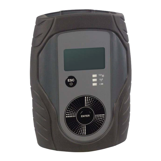
Page 7: Mvci Component Descriptions
MVCI Component Descriptions Connection Port Top Port Cover - Vehicle Cable Secure Digital Wireless Card SDIO Slot for SD Wireless Card or SD Memory Card Wireless Card Locking Retainer Clip Status Escape Button Lights: • Vehicle Off Button Communication •Wireless Connection •Battery Enter Button... - Page 8 Threaded Inserts (4) No. 4-40 unc (For future accessory Battery Cover attachment) Battery Cover Screws (2) No. 4-40 unc. x 0.375. Important: Damage will result and the warranty voided if a Battery Cover replacement screw exceeds 0.375 in length. Battery Cover removed Protocol Expansion...
-
Page 9: Mvci Screen Icon Descriptions
The wireless icon is only displayed when Honda Diagnostic System (HDS) is connected to the MVCI via a wireless connection. -
Page 10: Mvci Led Descriptions
MVCI LED Descriptions Vehicle Communication LED This LED lights solid green when the MVCI is communicating with the vehicle. Wireless Connection LED This LED lights solid blue when the wire- less card is confi gured. Battery Discharging LED When the MVCI is powered by its inter- nal battery this LED fi... -
Page 11: Mvci Software Installation
MVCI Software Installation NOTE: The SPX MVCI Installation will remove all of the previous SPX MVCI Installation. MVCI Application Installation Insert the CD into your personal computer (PC) CD-ROM tray. The install CD will automatically begin the installation procedure. NOTE: If installation does not automatically begin, go to the Start Menu (XP) or Windows Logo icon (Vista) >... -
Page 12: Mvci Driver Installation
MVCI Driver Installation NOTE: The MVCI Application (see previous page) must be installed before installing the MVCI Driver. The installed folder (C:\SPX). SPX must be on your PC main drive Plug the external power supply into the MVCI to boot it up. The following screen will appear. - Page 13 The “Found New Hardware Wizard” screen continues and asks “What do you want to do?” Select Install the software automatically (Recommended). Click Next.
- Page 14 A “Hardware Installation” screen will appear, click Continue Anyway. When the Installation is complete, click Finish to close the wizard. Installation is now complete. Restart the PC.
- Page 15 Vista Setup Windows Vista automatically installs the MVCI driver software. Observe the status and completion of its installation from your PC desktop. Installation is now complete. Restart the PC.
-
Page 16: Network Device
Network Device There are three types of network connections: USB, Wireless, and Ethernet. • USB Connection - If the USB cable is connected to the PC and MVCI (with power to the MVCI), the USB driver will be automatically recognized. Typically, when a USB connection is chosen, setup to the MVCI is not required. -
Page 17: Honda Diagnostic System (Hds) Setup
Honda Diagnostic System (HDS) Setup The MVCI can be used with HDS software. 1. Double-click the HDS shortcut icon on the desktop to start the HDS. 2. On the HDS Welcome Screen, click the F12 tab. NOTE: Please install the latest version of HDS. - Page 18 3. On the Setup screen, select SPX-MVCI in the drop down selection under Comms Interface. 4. The following screen is displayed when SPX-MVCI is selected. Press the Enter button on your keyboard or click the green check mark located in the lower right corner.
- Page 19 The HDS software will automatically restart and returns to the HDS Welcome screen. NOTE: If the following warning screen appears, press the Enter button on your keyboard or click the green check mark and try again after HDS terminates communication.
-
Page 20: Connecting To The Vehicle
Connecting to the Vehicle Connect the Vehicle Cable to the MVCI and to the Diagnostic Link Connector on the vehicle. The MVCI will power on automatically when power is received through the vehicle Diagnostic Link Connector. To turn off the MVCI, disconnect from the vehicle Diagnostic Link Connector, press the ESC button for 5 seconds. -
Page 21: Wireless Network Setup
Wireless Network Setup Setting up a Wireless Network requires the following steps: Access Wireless Network Setup. Select a Wireless Network Mode. Select and Set Up Wireless Security Set Up PC Communication to MVCI. Connect to MVCI. Begin by automatically powering on the MVCI with the AC power supply. -
Page 22: Step 2. Select A Wireless Network Mode
1-d. Select Network, press ENTER. 1-e. From Mode, select Peer to Peer, press ENTER. Step 2. Select a Wireless Network Mode 2-a. Select a Wireless Network Mode to set up: • Peer-to-Peer - MVCI and PC communicate directly to each other in a private wireless network. - Page 23 Do one of the following: • If you selected Peer-to-Peer, the Wireless Setup screen showing the active Channel will appear. Continue to Step 2-c. NOTE: Record the SSID for reference when you set up the PC to communicate with the MVCI. •...
- Page 24 2-b-2. Select SSID, press ENTER. An Edit SSID screen appears, it will allow you to manually enter the SSID of your Access Point. Scroll up/down to change the character and left/right to move between the characters of the SSID. Press the ENTER button when you have fi nished entering the SSID of the access point.
-
Page 25: Step 3. Select And Set Up Wireless Security
Step 3. Select and Set Up Wireless Security 3-a. From the Wireless Setup screen, select Security, press ENTER. • If you do not want to use wireless security, check to see that Disabled is displayed on the next screen. Then skip this step and go to Step 4: Set Up PC Communication to MVCI. - Page 26 3-b. Select an encryption mode for the Access Point you will connect to, press ENTER. NOTE: Ask your Information Technology (IT) Administrator for this information. • Disabled - Default mode, No security. • WEP-64Bit • WEP-128Bit 3-c. From the Security Setup screen, scroll down to Mode, select the current Mode, press ENTER.
- Page 27 3-e. From the Security Setup screen, scroll down to Key, select -- -- --, press ENTER. NOTE: Ask your Information Technology (IT) Administrator for this information. 3-f. Enter a key (WEP-64 requires 5 characters or 10 hexadecimal values, WEP-128 requires 13 characters or 26 hexadecimal values).
-
Page 28: Step 4. Set Up Pc Communication To Mvci
Step 4. Set Up PC Communication to MVCI NOTE: • Your PC must have internal wireless capability or an active external wireless card. • Your wireless radio must be enabled on your PC. Many laptop PCs have a software or hardware switch to enable or disable the wireless radio to allow use of a PC in a radio sensitive environment such as an airplane. - Page 29 4-f. Select the network in Access Point mode or a MVCI in Peer to Peer mode. Click Connect. NOTE: Ask your Information Technology (IT) Administrator for Access Point. 4-g. If the wireless security of the MVCI is an unsecured network, a warning message is displayed.
- Page 30 4-h. Connected is displayed when the connection between the PC and the MVCI is completed. IMPORTANT: When you have completed your diagnostics, make sure to disconnect Wireless Network Connection on the PC side and unplug the MVCI power supply. Select the MVCI which is con- nected in Wireless Network Connection screen and click Discon- nect.
- Page 31 Vista Setup 4-i. Click on the Windows Logo icon. 4-j. Click Control Panel. 4-k. Do one of the following: • Click View network status and tasks, OR • Double-click Network and Sharing Center 4-l. In the Network and Sharing Center window, click on the Manage network connections label provided on the left side panel named Tasks.
- Page 32 4-p. Select the network in Access Point mode or a MVCI in Peer to Peer mode. Click Connect. NOTE: Ask your Information Technology (IT) Administrator for Access Point. 4-q. If the wireless security of MVCI is an unsecured network, a warning message is displayed.
- Page 33 If the wireless security of the MVCI is a security-enabled network, type the Network key into the fi eld labeled Security key or passphrase. Click Connect. 4-r. Select Save this network and click Close. (If you do not wish to save this network setting, remove the checked selection and click Close.) NOTE: If the network setting is saved, it will not be necessary...
- Page 34 If the wireless security of MVCI is a security-enabled network and you select Save this network, the Network Location message is displayed. Click the Network Location “Work”. 4-s. Click Close.
- Page 35 4-t. The SSID of the MVCI which is connected with Network and Sharing Center is displayed when the connection is complete. IMPORTANT: When you have completed your diagnostics, make sure to disconnect the Wireless Network Connection on the PC side and unplug the MVCI power supply. Click Disconnect in the Network and Sharing Center screen.
-
Page 36: Step 5. Connect To Mvci
Step 5. Connect to MVCI 5-a. On your PC desktop, double-click the MVCI Discovery - Wireless icon (a utility installed from the MVCI Drivers CD). 5-b. On the MVCI Discovery utility screen, click Find SPX MVCI. - Page 37 5-c. If you have your MVCI in “Access Point” mode, a list of the MVCIs connected to the same Access Point network will display. If you have your MVCI in “Peer to Peer” mode, the MVCI selected in Step 4-f or 4-p will display. 5-d.
-
Page 38: Dlc Voltage
DLC Voltage Power up the MVCI using the Vehicle Diagnostic Link. After boot- up, press the ENTER button to enter the User Confi g screen. Select DLC Voltage. The vehicle battery voltage is displayed. -
Page 39: Mvci System Setup
MVCI System Setup Power up the MVCI. After boot-up, press the ENTER button to enter the User Confi g screen. Select MVCI Setup and press ENTER. The following setup options are available: • Clock • Language • SDIO-1 • SDIO-2 •... -
Page 40: Language
A Clock Setup menu appears: • To change the date, highlight the Date and press ENTER. Scroll up/down to change the number and left/right to move between the month, day, and year fi elds. Press ENTER to save the changes or ESC to cancel. •... -
Page 41: Sdio-1
SDIO-1 To enable/disable the SDIO-1 card slot on the MVCI, select SDIO- 1. The current status of the SDIO-1 card slot is displayed in the MVCI Setup menu. NOTE: This option should typically be left at the factory default setting (enabled). To change the card slot status, scroll up/down to move the cursor over the desired option. -
Page 42: Keybeep
Keybeep To enable/disable the beeping when the keypad is used, select Keybeep. The current status of the Keybeep is displayed in the MVCI Setup menu. Press ENTER to change status. From the Setup Screen, move the cursor over the desired option, press ENTER to save the change or ESC to cancel. -
Page 43: Factory Defaults
Scroll left/right to change the contrast percentage. Press ENTER to save the change or ESC to cancel. Factory Defaults To restore the MVCI to the factory default settings, select Restore under Factory Defaults, press ENTER. IMPORTANT: All Network confi guration settings will be reset to the following values: •... -
Page 44: Network Setup
Network Setup Power up the MVCI. After boot-up, press the ENTER button to enter User Confi g screens. Select Network Setup and press ENTER. The following setups are available: • Ethernet • USB Device • Wireless • DHCP Server... -
Page 45: Ethernet
Ethernet For most installations, the factory default settings should be used. The following Ethernet setup is included if you require a unique Ethernet setup due to the confi guration of your PC. Connect the MVCI to the PC with an Ethernet Crossover cable (not included). - Page 46 To change the Subnet mask, scroll down to highlight Subnet mask, press the ENTER button. Scroll up/down to change the number and left/right to move between the components of the subnet mask. Press the ENTER button to accept the changes, then press the ESC button to return to the previous menu.
-
Page 47: Usb Device
USB Device For most installations, the factory default settings should be used. The following USB setup is included if you require a unique USB setup due to the confi guration of your PC. To change the USB device network settings, select USB Device, press the ENTER button. -
Page 48: Wireless
To change the Subnet mask, highlight the Subnet mask, press the ENTER button. Scroll up/down to change the number and left/right to move between the components of the subnet mask. Press the ENTER button to accept the changes, then press the ESC button to return to the previous menu. - Page 49 Select Connection Mode, press the ENTER button. Select Static, press the ENTER button. The next screen will show the available service modes. For Peer to Peer connection, the Service should be set to Static. For Access Point connection, the Service should be set to DHCP Client.
- Page 50 To change the IP Address, highlight the IP Address and press the ENTER button. Scroll up/down to change the number and left/right to move between the components of the IP address. Press the ENTER button to accept the changes, then press the ESC button to return to the previous menu.
- Page 51 Select View, press the ENTER button. The next screen will show the Connections screen. From the LAN Setup, see illustration above, select View under Confi g, press the ENTER button. The Connections screen displayed next is for information confi rmation only. The settings cannot be changed from this screen.
-
Page 52: Dhcp Server
DHCP Server For most installations, the factory default settings should be used. This DHCP Server setup is included if you require a unique DHCP Server setup. The DHCP server setting controls whether the MVCI will act as a DHCP server for Ethernet and USB operation. To change the DHCP server setting, select DHCP Server, press the ENTER button. -
Page 53: System Status
System Status Power up the MVCI. After boot-up, press the ENTER button to enter the User Confi g screens. Select System Status and press ENTER. The following setup options are available: • SDIO-1 • SDIO-2 • Battery Charger • Host Status SDIO-1 To view the status of SDIO slot 1, select View status. -
Page 54: Sdio-2
Status screens appear, scroll down to see all status items. The screens illustrated above are status information only, no items may be changed. Press the ESC button to return to the previous menu. The information for SDIO slot 1 is typically for the MVCI memory card. SDIO-2 To view the status of SDIO slot 2, select View status. -
Page 55: Battery Charger
Battery Charger View the current state of the battery charging circuit. NOTE: In order to maximize battery life, the battery charging is cut-off when the internal temperature of the MVCI is at or above 60 degrees centigrade. Battery charging will resume once the MVCI power is cycled (turned off and on) and temperature is below 60 degrees centigrade. -
Page 56: Software Version
Software Version Power up MVCI. After boot-up, press the ENTER button to enter the User Confi g screens. Select Software Version and press ENTER. Scroll down to see the remaining software versions displayed. NOTE: Software screens show example data, actual data will vary. -
Page 57: Hardware Test
Hardware Test Power up the MVCI. After boot-up, press the ENTER button to enter the User Confi g screens. Select Hardware Test and press ENTER. The following setup options are available: • Buzzer Test • LED Test • LCD Test •... -
Page 58: Led Test
LED Test Select LED Test, press the ENTER button to turn on all of the LEDs for three seconds. LCD Test Select LCD Test, press the ENTER button to start a series of LCD tests. Press ENTER, all pixels are set to the on position. Press ESC to exit from the LCD test. -
Page 59: Keypad Test
After 5 seconds, the following screen appears. Press ENTER to display pattern 2 for 5 seconds. Press ESC to exit from the test. After 5 seconds, the last screen appears. Press ENTER to turn off all pixels for 5 seconds. Press ESC to exit from the test. Keypad Test Select Keypad Test, press the ENTER button to start the Keypad test. -
Page 60: Scroll Test
Scroll Test Select Scroll Test, press the ENTER button to start the Scroll test. To test the scroll function, move your fi nger around the scroll pad clockwise to scroll down. Move your fi nger around the scroll pad counter-clockwise to scroll up. Press the ESC button to exit the scroll test. -
Page 61: Device Loopback Test
Device Loopback Test Select Device loopback test, press the ENTER button to start the MVCI communication and analog circuit tests. IMPORTANT: Do not run this test if the MVCI is being powered through the vehicle cable. Run this test only when the MVCI is powered by the AC power adapter. -
Page 62: Sdmem Card Test
SDMEM Card Test Insert the SD memory card in either of the SDIO slots. Select the SDMEM Card Test, press the ENTER button to start the SDMEM Card Test. The following screen appears. When the test is fi nished, the condition of the card will display. The screen will return to the Hardware Test screen. -
Page 63: Auxiliary Pc Applications
Auxiliary PC Applications The installation CD for the MVCI contains three auxiliary PC applications. MVCI Discovery - Wireless This application is used to determine which MVCI to connect to when using a wireless connection. To launch the application do one of the following: •... -
Page 64: Mvci Firmware Update
MVCI Firmware Update This application is used to upgrade the MVCI independent of the Honda Diagnostic System (HDS). This application should not be used unless specifi cally directed to by Technical Service. To launch the application, do one of the following: •... -
Page 65: Mvci Registry Setting
MVCI Registry Setting This application is used to view/change the IP addresses used to communicate to the MVCI. This program also provides a mechanism to generate a MVCI debugging fi le. This application should not be used unless specifi cally directed to by Technical Service. Click All Programs >... -
Page 66: Frequently Asked Questions
Frequently Asked Questions • Why doesn’t my MVCI power on? Ensure that the MVCI is connected to the vehicle with the vehicle adapter cable or is connected to external power adapter. • Why doesn’t my MVCI power off? To turn off the MVCI, disconnect the MVCI from all power sources and press and hold the ESC button for three seconds. - Page 67 • Why does my MVCI beep every time the scroll pad is pressed? This is normal operation. This audible beep can be disabled. See the instructions for “Keybeep” in the MVCI System Setup section of this User Guide. • When using the menu functions, why does my MVCI return to the Host Status display? The MVCI will always return to the Host Status display after twenty seconds of no scroll pad activity.
- Page 68 Remove the top port cover. With the MVCI keypad facing you, slide the retainer clip to the right. Remove the retainer clip and place it in a safe area. Push the SD wireless card inward and release. The SD wireless card will release and eject partially.
-
Page 69: Useful Information
Useful Information Maintenance The SPX MVCI can become dirty being used in the automotive service environment. The MVCI surfaces can be cleaned by wiping them with a soft cloth. The soft cloth can be slightly damp with water or water and diluted, mild detergent. -
Page 70: Troubleshooting
Troubleshooting HDS software can not communicate with a vehicle Is the vehicle ignition ON? Turn ignition switch to the ON position Is the MVCI DLC connected to the vehicle connector? Connect MVCI DLC to the vehicle connector Retry Is the power to the MVCI Disconnect the MVCI from the vehicle connector... - Page 71 MVCI is connected to a different vehicle? DLC line open of the first vehicle Have you installed the SPX MVCI software from the CD-ROM included in the MVCI kit? Install the SPX MVCI software Install the SPX MVCI software from the CD-üüüüüü...
- Page 72 Option B Is the SD wireless card Is the SD wireless card properly inserted in properly inserted SDIO slot 1 or 2? üüüüüü 1 or 2? Properly insert the SD Properly insert the SD üüüüüü wireless card Retry Is the blue LED on the MVCI Press the ENTER button on the MVCI to enter “User Config”...
-
Page 73: Specifi Cations
Specifi cations Electrical 400MHz CPU Real Time Clock Display 65 x 128 pixel LCD Graphic Display Backlight Supports a maximum of 4 lines of text Status Lights Vehicle Communication Indicator Wireless Connection Indicator Battery Discharging Indicator Keypad Escape/Off Button Enter Button Scroll (Up/Down/Left/Right) Interface SDIO/SD Memory Card Slots (2) - Page 75 “Este produto está homologado pela ANATEL, de acordo com os procedimentos regulamentados pela Resolução 242/2000, e atende aos requisitos técnicos aplicados” Para maiores informações, consulte o site da ANATEL www.anatel.gov.br " Modelo: SPX MVCI 0984-09-4188 (01) 07898939454017...
Need help?
Do you have a question about the SPX MVCI and is the answer not in the manual?
Questions and answers