HYT TC-610 Service Manual
Hide thumbs
Also See for TC-610:
- Service manual (96 pages) ,
- Owner's manual (40 pages) ,
- Manual (11 pages)
Advertisement
Table of Contents
- 1 Specifications
- 2 General
- 3 Radio Overview
- 4 Software Specifications
- 5 Circuit Description
- 6 Semiconductor Data
- 7 Adjustment
- 8 Troubleshooting Flow Chart
- 9 Disassembly and Assembly
- 10 Exploded View
- 11 TC-610/620 Parts List 2
- 12 Packing
- 13 TC-610/620 PCB View
- 14 TC-610/620 Block Diagram
- 15 TC-610/620 Level Diagram
- 16 TC-610/620 Schematic Diagram
- Download this manual
General-------------------------------------------------------------------------------------2
Radio Overview-------------------------------------------------------------------------3
Software Specifications--------------------------------------------------------------7
Circuit Description---------------------------------------------------------------------8
Semiconductor Data----------------------------------------------------------------16
TC-610/620 Parts List 1-------------------------------------------------------------18
( U 1 ) ... ... ... ... ... ... ... ... ... ... ... ... ... ... ... ... ... ... ... ... ... ... ... ... . ... ... ... ... . ... ... ... ...
( U 2 ) ... ... ... ... ... ... ... ... ... ... ... ... ... ... ... ... ... ... ... ... ... ... ... ... ... ... ... ... ... . ... ... ... ...
Adjustment------------------------------------------------------------------------------46
Troubleshooting Flow Chart------------------------------------------------------56
Disassembly and Assembly-------------------------------------------------------55
Exploded View-------------------------------------------------------------------------64
TC-610/620 Parts List 2--------------------------------------------------------------66
Packing--------------------------------------------------------------------------------70
TC-610/620 PCB View----------------------------------------------------------------71
TC-610/620 Block Diagram---------------------------------------------------------74
TC-610/620 UHF ..........................................................................................
TC-610/620 Level Diagram------------------------------------------------77
TC-610/620 Schematic Diagram--------------------------------------------------80
(U1) Schematic Diagram (AF & IF & PLL)
(U1) Schematic Diagram (MCU & POWER).............................................................
(U1) Schematic Diagram (VCO & RF).............................................................
(U2) Schematic Diagram (AF & IF & PLL).................................................
CONTENTS
.........................................................
1
Advertisement
Table of Contents

Related Manuals for HYT TC-610


Summary of Contents for HYT TC-610
- Page 1 Semiconductor Data----------------------------------------------------------------16 TC-610/620 Parts List 1-------------------------------------------------------------18 ( U 1 ) … … … … … … … … … … … … … … … … … … … … … … … … . … … … … . … … … …...
-
Page 2: Specifications
(U2) Schematic Diagram (MCU & POWER)………………………………………….………… (U2) Schematic Diagram (VCO & RF)………………………………………….…… Specifications-----------------------------------------------------------------------81... -
Page 3: General
Do not modify the radio for any reason. Use only HYT original batteries and chargers. Use only the supplied or an approved antenna. Do not use any portable radio that has a damaged antenna. If a damaged antenna comes into contact with your skin, a minor burn can result. -
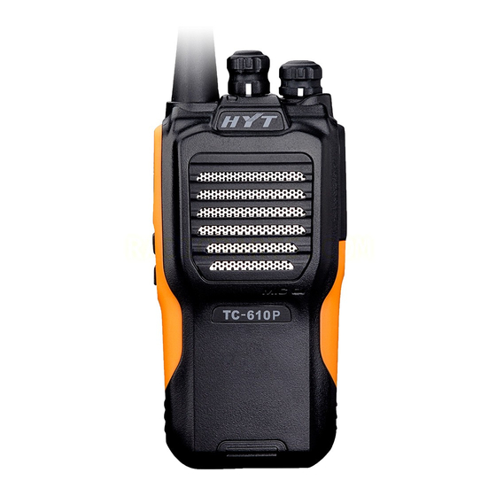
Page 4: Radio Overview
Radio Overview TC-610 ① PTT ② SK1 (programmable key) ③ SK2 (programmable key ④ Speaker ⑧ Channel ⑤ Microphone ⑥ Antenna ⑦ LED Selector Knob ⑨ On-Off/Volume ⑪ Earpiece Jack ⑩ Battery Latch ⑫ Earpiece Cover Control Knob Programming Port ⑬... - Page 5 TC-620 ① PTT ② SK1 (programmable key) ③ SK2 (programmable key ④ Speaker ⑧ Channel ⑤ Microphone ⑥ Antenna ⑦ LED Selector Knob ⑨ On-Off/Volume ⑪ Earpiece Jack ⑩ Battery Latch ⑫ Earpiece Cover Control Knob Programming Port ⑬ Belt Clip ⑭...
- Page 6 Side key 1, programmable. Your dealer can program the key with a function via the programming software. Side key 2, programmable. Your dealer can program the key with a function via the programming software. LED statuses and alert tones: Power on the source radio while holding down the SK2 key.
- Page 7 LED glows red. When transmission times out, “BEEP” tone sounds Transmit continuously. TOT pre-alert: “BEEP” tone sounds once. Receive When a carrier is received, LED glows green. When detecting, LED flashes green every second. Scan start tone (programmable by your dealer): “BEEP” tone sounds once.
-
Page 8: Software Specifications
Turn the knob clockwise to increase the volume, or counter-clockwise to decrease the volume. Software Specifications Functions 1. Available Channels: 1 to 16 channels Frequency Range: UHF: 400-420MHz UHF: 450-470MHz 2. Channel Spacing: 25KHz/12.5KHz 3. Channel Step: 5/6.25/10/12.5KHz channel scan function 4. -
Page 9: Circuit Description
Circuit Description Realization Methods for Basic Functional Modules PLL Frequency Synthesizer The PLL circuit generates local oscillator signals for reception and RF carrier signals for transmission. The PLL circuit consists of the VCO oscillator circuit and baseband processor chip and realizes frequency tracking and channel conversion under the control of MCU signals. - Page 10 U202 generates a control voltage via the phase comparator to control varactors (D100 and D101 in transmitting mode; D102 and D103 in receiving mode) to bring the oscillator frequency of VCO in line with the preset frequency of MCU within a broader frequency range. The switching tube Q652 switches between transmitting and receiving under the control of T/R.
- Page 11 TUNE FROM MCU TUNE FROM MCU Q500 C521 C524 C505 D505 D507 D506 D503 D504 C526 C523 C506 C519 C504 L508 L507 L506 L502 L501 TUNE BPF TUNE BPF Figure 4 The Rx signals input from the antenna is filtered to remove out-of-band signals at the electrically tunable bandpass network (D503, D504, L501, L502, C503, C505 and 507) and then amplified by low-noise amplifier (LNA) Q500 to obtain a certain level required by reception.
- Page 12 is utilized. The mixer tube (Q501) utilizes dual gate FET MOS (3SK318) and has better noise characteristics and square law characteristics. The isolation between the local oscillator signals and the Rx signals is high. To ensure proper sensitivity and certain gain for the mixer tube, tune delicately via the offset.
- Page 13 Audio and Signalling Processing Circuit Baseband processing IC AN29160 has high integration level and powerful functions. Many of the processing functions (as VCO level detect&output, SQ signal level detect&output, Tx-Rx audio processing switch, audio amplifier, etc) and can be realized inside. The Tx-Rx sharing can also be realized.
- Page 14 Block Diagram for Rx Audio&Signalling Process 2ndIF BPF CF300 450KHz+/4.5K SPVCC To MCU IFAmp1 U200 DATA AN29160AA RSSI IFAMP2 LATCH POWERREG PROCESSER mix2 volume mute VREF 5th-HPF Mic amp sp Amp (TX) tone-LPF mic mute AMP(TX) 5th-LPF 信令输出 AUDIO OUT 16Ω...
- Page 15 MCU Control Section The block diagram for the MCU control section is shown below. MCU works under the 7.3728MHz clock frequency. U609 A T 2 4 C 6 4 Channel SW 1.vox 2.BUSY_DET 3.BEEP/CALL U605 4.T/R APC/TUNE 5.SAVE 6.DC/CTC 7.W/N 8.UART MB95F108AK 9.BAT_DET...
- Page 16 Detect of external PTT, MONI and VOX Detect of PLL unlock (UL) Detect of VOX ON level Detect of battery power alarm Detect of enabling and checking external remote speaker microphone Data Transfer and Process EEPROM data initiation Programming data transfer Encoding process of channel selector knob Signalling encoding and decoding Data transfer of baseband processing chip (PLL)
- Page 17 (control signal of SAVE). When the SAVE signal of MCU is of high level, Q610 becomes conductive and provides a 5V voltage (V_SAVE) for the operating circuit. PLL and the receiving circuit operate. When the SAVE signal is a pulse signal, the radio enter the battery save mode. When transmitting, TXC, control signal of CPU, is of high level.
-
Page 18: Semiconductor Data
EXT-PTT is of low level. MCU detects as the remote speaker microphone without VOX and the radio returns to the common mode. Press the PTT key on the remote speaker microphone to transmit. Semiconductor Data Pin Name TC-610 TC-620 Description Power supply pin for A/D, connecting power AVcc... - Page 19 pin and the grounded Vss. When not downloading, only a resistor of 47K is connected between the pin and the grounded Vss. OSC0 OSC0 Connecting pin of 7.3728MHzMHz master crystal oscillator OSC1 OSC1 Power supply (GND) pin (When recording, it is connected with the GND recording port signals.) MCU 5V power supply (When recording, it is connected with the VCC recording port signals)
- Page 20 P50/SCL0 EEPROM CLOCK P51/SDA0 EEPROM DATA P52/PPG1 AP/TU AP/TU Auto power control/adjust Tx power supply control “H”: valid P53/TRG1 TX_CTRL TX_CTRL Transmission is on. P60/PPG10 PLLCLK PLLCLK O PLL CLK P61/PPG11 PLLDATA PLLDATA O PLL DATA P62/TO10 PLLEN PLLEN O PLL ENABLE P63/TO11 Reserve Reserve...
-
Page 21: Adjustment
Adjustment User Mode Power on the radio to enter the conventional mode when no key is pressed. Programming Mode In user mode, the PC programming software triggers the PC programming mode by communication through a special communication protocol. The programming mode can set functions and adjustment parameters of the radio via the PC programming software (including user version and factory version). - Page 22 clone data into the slave radio. During communication, LED of the mother radio flashes red, while LED of the slave radio flashes green. When the communication is completed, red LED of the mother radio and green LED of the slave radio go out, preparing for the next cloning. During communication, if an exception occurs, the communication will be terminated.
- Page 23 CTCSS deviation (low), CTCSS deviation (medium), CTCSS deviation (high), VOX 1, VOX 2, VOX 3, VOX 4, VOX 5 and Tx low voltage threshold respectively. Note: Tx medium power of TC-610/620 is not required to be adjusted. Please skip this item. LED glows red for the adjustment items CH1-CH14.
- Page 24 Hold down SK1, and the adjustment value decreases continuously in step of 1. When the adjustment value gets to the minimum value allowed by the adjustment item, the adjustment value will keep the minimum value constant. Process on Several Exceptional Items Tx: CH9-CH14 indicate VOX 1, VOX 2, VOX 3, VOX 4, VOX 5 and Tx low voltage threshold respectively, which are related with the AD sampling.
- Page 25 TC-610/620 Adjustment Items Wide Narrow Channel Adjustable Freq. Freq. 1 Freq. 2 Freq. 3 Freq. 4 Freq.5 Freq. 1 Freq. 2 Freq. 3 Freq. 4 Freq. 5 Tx Section Adjust preset RF power Tx low power Reserved channel (not adjust)
- Page 26 Tx frequency tolerance, VCO lock voltage adjustment, maximum deviation and modulation sensitivity Note: These items are adjusted outside the adjustment mode (unnecessary to enter the adjustment mode) via the hardware adjustment. Tx low power, Tx high power, CDCSS waveform, CDCSS deviation, CTCSS deviation (low), CTCSS deviation (high) and Tx low voltage threshold Note: These items are adjusted inside the adjustment mode via the software adjustment.
- Page 27 lock voltage is within the required range. Rotate to ≥2.3V Check CH3. Rotate Adjust VR200 with a CH1, ceramic alignment respectively. Wide screwdriver to limit 3.7-4.3KHz Press Radio the deviation to the to transmit. communication specified range. Max. test set Rotate VR200 Deviation...
- Page 28 Rotate to CH2. Press PTT to enable Press SK1/SK2 function. increase/decrease the Low frequency output power 2W±0.3W Short press rotate channel I≤1.2A PTT to switch selector knob to save. frequencies periodically (refer adjustment list) Adjust VR260 with a Rotate to CH5. ceramic alignment Radio...
- Page 29 Low frequency Press PTT to switch other frequencies (medium-low, medium, medium-high and high) Rotate CH6, CH7 and respectively Adjust VR601 with a and CTCSS is ceramic alignment low, screwdriver and check medium each frequency. Wide high. Press Adjust finely with SK1 500-800Hz PTT to enable and SK2 to limit the...
- Page 30 Specification/ Item Condition Test Equipment Parts Method Remarks Check whether Rotate to CH8. SINAD is within the Low frequency Radio Adjust the range and whether to communication volume control Antenna get SINAD≥12dB by test set knob to the Sensitivity Remote adjusting SK1 or SK2.
- Page 31 Rotate to CH5 and SQL is set to level 5 OFF. Press SK1 or Adjust the output SK2 to enable signals of SSG to the Radio Antenna function. squelch level. Rotate SQL level: Wide communication Remote channel the channel selector -121±1dB test set speaker MIC...
- Page 32 Appendix: Reference Voltage Setting of Battery Capacity Check in transmitting mode > Green 7.35V 18min (70%-100%) Orange 7.15V - 7.35V 12min (50%-70%) Red LED (30%-50%) 7.00V - 7.15V 12min flashes 18min 6.20V 7.00V LED flashes red 5.80V 6.20V +an alarm tone sounds every Halt...
-
Page 33: Troubleshooting Flow Chart
Troubleshooting Flow Chart Tx Section Start Low Tx No voice during Tx LED not Replace power transmission transmission light D602 Normal Tx Check Tx power supply? power supply Check voice channel (MIC, VR200 and D104) D602 glows Tx VCO is Check Tx red? locked? - Page 34 Rx Section Start No receive Normal power Check Rx power supply of receiving supply circuit circuit? Rx frequency is Change Rx Normal Rx LED? correct? frequency Rx signalling is Change Rx Rx squelch level is Change Rx correct? signalling correct? squelch level Speaker works Replace the...
- Page 35 Start Normal power-on alert tone? Replace the Speaker works well? speaker MCU operating voltage Check U606 VCC works well? MCU clock crystal X601 Replace X601 works well? Check pin Check whether other connection or control pins control well. recording programme MCU works well...
-
Page 36: Disassembly And Assembly
Disassembly and Assembly Attaching the Battery ① Hold the battery and push it towards the top of the aluminum chassis under the belt clip of the radio. See figure 1. Note: Insert the tabs at the top of the battery into the top of the battery slots. Figure 1 ②... - Page 37 ② Release the battery latch and remove the battery when the bottom of the battery tilts. See figure Note: To avoid serious abrasion between the tab on the top of the battery and the slot on the top of the radio, the angel between the radio unit and the tilting battery must not be too large. Figure 2 Attaching the Antenna ①...
- Page 38 Removing the Antenna Rotate the antenna counter-clockwise to remove the antenna. Attaching the Belt Clip Loose the screw for the belt clip and fix the belt clip on the radio unit. Align the hole on the belt clip with that on the aluminum chassis and rotate the screw for the belt clip clockwise to fasten the clip. See figure 1.
- Page 39 Figure 2 Attaching the External Earphone/Microphone ① Open the earphone/microphone jack cover (unnecessary to remove). See figure 1. Figure 1 ② Plug the earphone/microphone into the jack and fasten the screw. See figure 2. Figure 2...
- Page 40 Removing the External Earphone/Microphone Loose the screw and unplug the earphone/microphone. Note: When the external earphone/microphone is used, the radio’s waterproof performance will be affected.
-
Page 41: Exploded View
Exploded View TC-610... - Page 42 TC-620...
-
Page 43: Tc-610/620 Parts List 2
TC-610/620 Parts List 2 TC-610 Material No. Description Qty. 6000631000000 Volume control knob 6201006000000 Inner liner knob 7207002200200 6100325000000 O-RING (knob) 1500006100000 Front case kit 6000634000000 Plastic PTT key 6100312000000 Silica rubber PTT key 6100307000000 Waterproof ring (main unit) 4303020000020... - Page 44 TC-620 Material No. Description Qty. 7102003500100 Machine screw 6000639000000 Earpiece cover 6300040000000 Decorative plate (zinc alloy) 6000127000000 Earpiece cover stopper 1500006200000 Front case kit 5001210000170 Speaker 7400141000000 NSM08Z01mic net 6100123000000 MIC cover 6100323000000 Holder (speaker jack) 7102004021030 Self-tapping screw ST2.0*3.8mm 5002220000050 5205000000280 Speaker jack...
-
Page 45: Packing
Packing... -
Page 46: Tc-610/620 Pcb View
TC-610/620 PCB View... -
Page 47: Tc-610/620 Block Diagram
TC-610/620 Block Diagram... -
Page 48: Tc-610/620 Level Diagram
TC-610/620 Level Diagram TX PART 16mVrms 450mVrms 150mVrms -45dBm -26dBm -8dBm 3dBm 15dBm 27dBm 39dBm 37dBm buffer stimulator power AMP Q400 2SC5108 Q401 2SK4988 AN29160 MICROPHONE Q402 Q403 Q100 Q104 C112 2SK508NV Q102 D400 2SK3475 RQA0002 C429 C130 C141 C400... -
Page 49: Tc-610/620 Schematic Diagram
7.5V DC Battery Life ( 5-5-90 Duty About 8 hours Cycle) Operating Temperature -20~+50℃ TC-610:119mm x 54.6mm x 32.5mm (without antenna) Dimensions (H×W×D) TC-620:117mm x 54.3mm x 31mm (without antenna) TC-610: 270g (with antenna) Weight TC-620: 275g (with antenna) Frequency Stability ±2.5ppm... - Page 50 HYT endeavors to achieve the accuracy and completeness of this manual, but no warranty of accuracy or reliability is given. All the specifications and design are subject to change without prior notice due to continuous technology development. Changes which may occur after publication are highlighted by Revision History contained in Service Manual.