Table of Contents
Advertisement
www.proform.com
Model No. PFEX01416.1
Serial No.
USER'S MANUAL
Write the serial number in the space
above for reference.
Serial Number
Decal
ACTIVATE YOUR
WARRANTY
To register your product and
activate your warranty today,
go to www.proformservice.com/
registration.
CUSTOMER CARE
For service at any time, go to
www.proformservice.com.
Or call 1-877-660-1168
Mon.–Fri. 6 a.m.–6 p.m. MT
Sat. 8 a.m.–12 p.m. MT
Please do not contact the store.
CAUTION
Read all precautions and
instructions in this manual before
using this equipment. Keep this
manual for future reference.
Advertisement
Table of Contents

Subscribe to Our Youtube Channel
Related Manuals for ProForm PFEX01416.1


Summary of Contents for ProForm PFEX01416.1
- Page 1 Model No. PFEX01416.1 Serial No. USER’S MANUAL Write the serial number in the space above for reference. Serial Number Decal ACTIVATE YOUR WARRANTY To register your product and activate your warranty today, go to www.proformservice.com/ registration. CUSTOMER CARE For service at any time, go to www.proformservice.com.
- Page 2 PROFORM and IFIT are registered trademarks of ICON Health & Fitness, Inc. LE TOUR DE FRANCE is a regis- tered trademark of Société du Tour de France. Google Maps is a trademarks of Google Inc. The BLUETOOTH ®...
-
Page 3: Important Precautions
IMPORTANT PRECAUTIONS WARNING: To reduce the risk of burns, fire, electric shock, or injury to persons, read all important precautions and instructions in this manual and all warnings on your training bike before using your training bike. ICON assumes no responsibility for personal injury or property damage sustained by or through the use of this product. - Page 4 15. The training bike should not be used by 17. Always keep your back straight while using persons weighing more than 350 lbs. the training bike; do not arch your back. (159 kg). 18. Over exercising may result in serious injury 16.
- Page 6 STANDARD SERVICE PLANS...
-
Page 7: Before You Begin
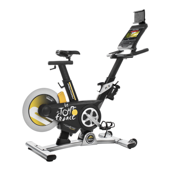
BEFORE YOU BEGIN Congratulations for selecting the revolutionary reading this manual, please see the front cover of this PROFORM LE TOUR DE FRANCE training bike. manual. To help us assist you, note the product model ® ® The LE TOUR DE FRANCE training bike is unlike any number and serial number before contacting us. -
Page 8: Part Identification Chart
PART IDENTIFICATION CHART Use the drawings below to identify the small parts needed for assembly. The number in parentheses below each drawing is the key number of the part, from the PART LIST near the end of this manual. The number following the key number is the quantity needed for assembly. -
Page 9: Assembly
ASSEMBLY • To hire an authorized service technician to • To identify small parts, see page 8. assemble the training bike, call 1-800-445-2480. • In addition to the included tool(s), assembly • Assembly requires two persons. requires the following tools: one Phillips screwdriver •... - Page 10 3. If there are shipping screws in the Rear Stabilizer (23), remove and discard them. Attach the Rear Stabilizer (23) to the Base (1) with two M10 x 58mm Screws (74). 4. Using a plastic bag to keep your fingers clean, apply some of the included grease to the sides Grease of the channel on the top of the Saddle Post (3).
- Page 11 5. Note: You can attach your own saddle to the Saddle Carriage (4) if desired. Loosen the attachment hardware (not shown) beneath the Saddle (5), and remove the Saddle. Then, attach your own saddle and retighten the attachment hardware. Orient the Saddle Carriage (4) as shown. Loosen the Adjustment Handle (47), and slide the Saddle Carriage (4) into the Saddle Post (3).
-
Page 12: Screw (95
7. Have a second person hold the Handlebar (7) near the Handlebar Carriage (105). Locate the wire tie (D) in the right side of the Handlebar (7). Tie the indicated end of the wire tie to the Right Control Wire (81), which is marked with a tag. - Page 13 10. Have a second person hold the Console (9) near the Console Bracket (124). Connect the console wires to the Ground Wire (133), the Handlebar Post Wire (68), and the Control Wires (70, 81); make sure to connect the console wire that has an “L” tag to the Control Wire that has an “L”...
- Page 14 13. Note: You can attach your own pedals if desired. Identify the Right Pedal (62). Using the included flat wrench tool, firmly tighten the Right Pedal (62) clockwise into the Right Crank Arm (64). Firmly tighten the Left Pedal (not shown) counterclockwise into the Left Crank Arm (not shown).
-
Page 15: How To Use The Training Bike
HOW TO USE THE TRAINING BIKE HOW TO PLUG IN THE POWER CORD A temporary adapter may 2-pole Receptacle This product must be grounded. If it should mal- be used to function or break down, grounding provides a path of connect the Adapter least resistance for electric current to reduce the risk... - Page 16 FEATURES OF THE TRAINING BIKE HOW TO ADJUST THE GEOMETRY OF THE TRAINING BIKE Measuring Watts The training bike can be adjusted to promote correct Each training bike is individually calibrated to measure form and to ensure proper training of the muscles. your power output and allow you to monitor your watts Note: Make adjustments in small increments, and and RPMs directly on the console.
- Page 17 How to Adjust the Saddle Post How to Adjust the Handlebar Post For effective train- To use the pedals ing, the saddle (O), insert your should be at the shoes into the toe proper height. As cages and pull the you pedal, there ends of the toe should be a slight...
- Page 18 HOW TO USE THE TABLET HOLDER HOW TO USE THE PEDALS IMPORTANT: The tablet holder is designed for use To use the toe cage with most full-size tablets. Do not place any other side of the ped- electronic device or object in the tablet holder. als (O), insert your shoes into the toe To insert a tab-...
- Page 19 CONSOLE DIAGRAM MAKE YOUR FITNESS GOALS A REALITY WITH Upload your workout results to the iFit cloud IFIT.COM and track your accomplishments. With your new iFit-compatible fitness equipment, you can use an array of features on iFit.com to make your Set calorie, time, distance, or watts goals fitness goals a reality: for your workouts.
- Page 20 FEATURES OF THE CONSOLE HOW TO TURN ON THE POWER The advanced console offers an array of features IMPORTANT: If the training bike has been exposed to cold temperatures, allow it to warm to room tem- designed to make your workouts more effective and perature before you turn on the power.
- Page 21 HOW TO USE THE TOUCH SCREEN network. See HOW TO USE THE WIRELESS NETWORK MODE on page 31 to connect the The console features a tablet with a full-color touch console to your wireless network. screen. The following information will help you become 2.
- Page 22 HOW TO USE THE MANUAL MODE Change gears (resistance) by pressing the Gears increase and decrease buttons on the console or 1. Touch the screen or begin pedaling to activate on the right handlebar. the console. Note: After you press a button, it will take a See HOW TO TURN ON THE POWER on moment for the training bike to change to the page 20.
- Page 23 6. Do intervals if desired. 8. Turn on the fan if desired. During a workout, you can use the interval screen The fan has sev- to measure your performance for short periods of eral speed settings, time. To select the interval screen, simply flick or including an auto slide the screen.
- Page 24 HOW TO USE A LE TOUR DE FRANCE WORKOUT At the end of the first segment of the workout, the incline will automatically adjust to the incline level 1. Touch the screen or begin pedaling to activate for the next segment. the console.
- Page 25 HOW TO USE A SET-A-GOAL WORKOUT The workout will continue until you reach the goal that you set. A workout summary will appear on 1. Touch the screen or begin pedaling to activate the screen. After you view the workout summary, the console.
- Page 26 HOW TO USE AN IFIT WORKOUT 5. Select an iFit workout. Note: To use an iFit workout, you must have access IMPORTANT: Before iFit workouts will download, you must add them to your schedule to a wireless network (see HOW TO USE THE on iFit.com (see step 1).
- Page 27 7. Follow your progress. HOW TO USE THE EQUIPMENT SETTINGS MODE See step 5 on page 22. The screen may also IMPORTANT: Some of the features described may not be enabled. Occasionally, a firmware update may show a map of the route and a marker indicating your progress.
- Page 28 6. Turn on or turn off the display demo mode. 10. Enable or disable a passcode. The console features a display demo mode, The console features a child safety passcode, designed to be used if the training bike is displayed designed to prevent unauthorized users from using in a store.
- Page 29 13. Adjust the resistance offset. When you select an update time, you must also enable automatic console updates (see step 4). If your power output in watts shown in the display IMPORTANT: You must still unplug the power does not seem to be accurate, you can adjust the cord after using your training bike.
- Page 30 HOW TO USE THE MAINTENANCE MODE Note: Occasionally, a firmware update may cause your console to function slightly differently. These IMPORTANT: Some of the features described may updates are always designed to improve your train- not be enabled. Occasionally, a firmware update may ing experience.
- Page 31 HOW TO USE THE WIRELESS NETWORK MODE When a list of networks appears, touch the desired network. Note: You will need to know your network The console features a wireless network mode that name (SSID). If your network has a password, you allows you to set up a wireless network connection.
- Page 32 HOW TO USE THE SOUND SYSTEM To enter a different web address in the URL bar, first, slide your finger down the screen to view the URL bar, To play music or audio books through the console if necessary. Then, touch the URL bar, use the key- sound system while you exercise, plug a 3.5 mm male board to enter the address, and touch the Go button.
-
Page 33: Fcc Information
FCC INFORMATION This equipment has been tested and found to comply with the limits for a Class B digital device, pursuant to part 15 of the FCC Rules. These limits are designed to provide reasonable protection against harmful interference in a residential installation. This equipment generates, uses, and can radiate radio frequency energy and, if not installed and used in accordance with the instructions, may cause harmful interference to radio communications. -
Page 34: Maintenance And Troubleshooting
MAINTENANCE AND TROUBLESHOOTING HOW TO MAINTAIN THE TRAINING BIKE HOW TO ADJUST THE DRIVE BELT Regular maintenance is important for optimal If the pedals slip while you are pedaling, the drive belt performance and to reduce wear. Inspect and properly may need to be adjusted. -
Page 35: Exercise Guidelines
EXERCISE GUIDELINES Aerobic Exercise—If your goal is to strengthen your WARNING: cardiovascular system, you must perform aerobic Before beginning this exercise, which is activity that requires large amounts or any exercise program, consult your physi- of oxygen for prolonged periods of time. For aerobic cian. - Page 36 SUGGESTED STRETCHES The correct form for several basic stretches is shown at the right. Move slowly as you stretch; never bounce. 1. Toe Touch Stretch Stand with your knees bent slightly and slowly bend forward from your hips. Allow your back and shoulders to relax as you reach down toward your toes as far as possible.
-
Page 37: Part List
PART LIST Model No. PFEX01416.1 R0517A Key No. Qty. Description Key No. Qty. Description Base Board Bracket Frame Standoff Saddle Post Crank/Torque Pulley Saddle Carriage M4 Washer Saddle Magnet Handlebar Post Crank Screw Handlebar Bearing Tray Push Nut Console Frame Bushing... - Page 38 Key No. Qty. Description Key No. Qty. Description Reed Switch/Wire Tablet Holder Crank Hub Swivel Tube Crank Spacer Swivel Bushing M8 Locknut Swivel Tube Cap Handlebar Carriage Handlebar Carriage Cover M8 x 20mm Screw Console Bracket Right Extension Wire Swivel Tube Bushing Left Extension Wire M8 x 35mm Screw M4 x 9mm Screw...
-
Page 39: Exploded Drawing
EXPLODED DRAWING Model No. PFEX01416.1 R0517A... -
Page 40: Ordering Replacement Parts
ORDERING REPLACEMENT PARTS To order replacement parts, please see the front cover of this manual. To help us assist you, be prepared to provide the following information when contacting us: • the model number and serial number of the product (see the front cover of this manual) •...
Need help?
Do you have a question about the PFEX01416.1 and is the answer not in the manual?
Questions and answers