Table of Contents
Advertisement
Quick Links
Advertisement
Table of Contents

Related Manuals for CTM 3600-PA


Summary of Contents for CTM 3600-PA
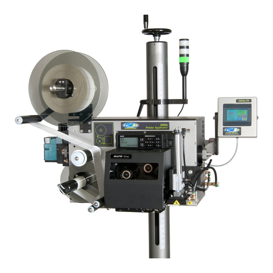
- Page 1 1318 QUAKER CIRCLE P.O. BOX 589 SALEM, OHIO 44460 PHONE: 330-332-1800 FAX: 330-332-2144 www.ctmlabelingsystems.com Designers and Manufacturers of Pressure Sensitive Labeling Equipment and Custom Product Handling 3600 PRINTER APPLICATOR MAINTENANCE & SERVICE MANUAL (REVISION 3600-2b5.x)
-
Page 2: Table Of Contents
TABLE OF CONTENTS TABLE OF CONTENTS (STANDARD 3600) TABLE OF FIGURES …………………………………………………………. 1 INTRODUCTION ………………………………………………………….…... 2 WEB PATH ……………………………………………………………………... 3 MACHINE TERMS ……………………………………………………………. 4 APPLICATOR DISPLAY ……………………………………………………... 5 Key Descriptions ……………………………….………..… 5-1 Changing Variable Fields ……………………………...…... 5-2 Alarm Screens ………………………………………...….… 5-3 REAR PANEL ………………………………………………………………….. - Page 3 TABLE OF CONTENTS TROUBLESHOOTING ………………………………………………………... 11 PRINTER SETTINGS ………………………………………………………… 12 Sato Printers ……………………………………………….. 12-1 Zebra Printers ……………………………………………… 12-7 Datamax Printers …………………………………………… 12-7 RECOMMENDED SPARE PARTS ………………………………………….. 13 AND DRAWINGS SUPPLIMENTS TO STANDARD 3600 MANUAL Dual Action Tamp ………………………………………….… Section B Corner Wrap ………………………………………………….
-
Page 4: Table Of Contents
TABLE OF FIGURES TABLE OF FIGURES FIGURE 1 (Unwind Assembly) ……………………………………………… 7-1 FIGURE 2 (Valve Bank) ……………………………………………………… 7-2 FIGURE 3 (Standard Tamp Assembly) ………………………………………. 7-3 FIGURE 4 (Extended Peel Edge Assembly) …………………………………. 7-4 FIGURE 5 (Swing Tamp) …………………………………………………….. 7-5 FIGURE 6 (Web Path) ……………………………………………………...… 7-6 FIGURE 7 (Applicator in Nose Down Attitude) ……………………………... - Page 5 TABLE OF FIGURES FIGURE 24 (S18SN6FF50 Product Detect Sensor) ……………………………. b6-3 FIGURE 25 (Apply Sequence) …………………………………………………. c3-1 FIGURE 26 (Apply Sequence) …………………………………………………. c3-2 FIGURE 27 (Apply Sequence) …………………………………………………. c3-3 FIGURE 28 (Corner Wrap Valve Banks) ……………………………………….. c3-4 FIGURE 28 (Web Path Powered Unwind) ……………………………………… d2...
- Page 6 INTRODUCTION INTRODUCTION The 3600-PA printer applicator is a high-speed labeler used to thermally print and apply pressure sensitive labels to moving products. A thermal transfer printer is integrated into an applicator to form a self-contained unit that will print variable data onto a label. The printer/applicator can be mounted in almost any position adjacent to product flow to apply labels to top, sides or bottom of products as they pass by.
- Page 7 If the applicator doesn’t operate correctly, back-up and start over. FOLLOW ALL SAFETY INSTRUCTIONS. The 3600-PA has been provided with a number of safety features. Observe all safety warning and under no circumstances attempt to remove or...
- Page 18 MACHINE TERMS MACHINE TERMS Adhesive Strings: Label adhesive that attaches to the label and liner while the label is dispensing onto the label pad. They can cause the label position on the label pad to become inconsistent. Air Assist Tube: A small diameter tube with small hole in it mounted under the peel edge. The purpose is to direct a stream of air to help the label onto the label pad.
- Page 19 MACHINE TERMS Label Placement: The time from when the product sensor is made to when the labeling sequence starts. Label Sensor: The sensor that detects the leading or trailing edge of the label. Label Size: The width and length (or feed) of a label. Length equals the distance from the leading edge of the label to its trailing edge.
- Page 20 APPLICATOR DISPLAY APPLICATOR DISPLAY PANEL On power-up, the display will scroll the software version screen for 30 seconds. This will allow time for all of the different types of printers to go through their diagnostics. The applicator can be switched from Normal Tamp mode to Inverted Tamp Mode through the display. See the applicator setup section on how to do this.
-
Page 21: Changing Variable Fields
APPLICATOR DISPLAY Home/Tamp: When scrolling through sub-menus, pressing “Home” will return you to the Home Page (main menu). If you’re at the main menu and tamp is enabled, press the “Home” key to extend the tamp slide (nothing will happen if in ITB mode). With the tamp extended, the print head on the printer can be opened. -
Page 22: Alarm Screens
APPLICATOR DISPLAY Alarm Screens The operator interface will display alarm screens for the following alarms: Low Label - signal from sensor mounted on the unwind of the applicator. Low Ribbon - signal from the printer. No Label/Ribbon - signal from the printer. ... - Page 23 REAR PANEL REAR PANEL Connector Descriptions VALVE: Valve bank connection. Valve banks come with a short cable and a plug. ALARM: Alarm light connection . Will drive up to a three stack light stack. (one light for printer ready, one light for warning, and one for critical alarms) PRODUCT: Product detect sensor connection.
-
Page 24: I/O Port Functions
REAR PANEL I/O Port Functions The following is a list of the pre-wired functions of the I/O port. If other functions are needed (i.e. tamp home switch), they can easily be added. All outputs are NPN (sinking) with 80 ma load. -
Page 25: Figure 1 (Unwind Assembly)
APPLICATOR SETUP APPLICATOR SETUP When an applicator is shipped, it may be necessary to for some disassembly The following section will show different assemblies to aid in putting the applicator back together so it can be set up. Unwind Assembly The unwind assembly mounts to the applicator by fastening the unwind mounting plates(2) to the unwind and to the applicator face in alternate positions to suit various orientation and clearance requirements (refer to drawing # ASS-238-0123, MP-238-0236). -
Page 26: Air Filter Installation
APPLICATOR SETUP Air Filter Installation When the applicator is shipped, the air filter is off. The filter is sent with two 2” nipples and an elbow. The attitude of the machine will determine how the filter should be plumbed. Note: In all cases it is important to have the filter bowl pointing down. -
Page 27: Figure 3 (Standard Tamp Assembly)
Figure 2 shows two types of valve bank assemblies. At the bottom is a Mac Type Valve assembly which CTM started using in the Spring of 2007. If the valve bank was removed and needs to be re-mounted, decide on which side of the applicator the valves should be mounted. Normally, the valves are mounted on the opposite side from the applicator nose. -
Page 28: Figure 4 (Extended Peel Edge Assembly)
APPLICATOR SETUP Extended Peel Edge Assembly This nose assembly is used when it is desired to disable the backfeed option on the applicator to gain more labels per minute. With the backfeed off, the leading edge of labels will stop in different places with different length labels. -
Page 29: Figure 5 (Swing Tamp)
APPLICATOR SETUP Swing Tamp Assembly This assembly is used to apply labels on the leading or trailing edge of products. The assembly is held on to the sideframe by four ¼ shcs. marked as side to side adjustment in Figure 5. These same four bolts will allow the assembly to move across web path to line the label to the pad. -
Page 30: Figure 6 (Web Path)
APPLICATOR SETUP Ribbon Loading 1- At the main menu, press the “Home/Tamp” key (refer to the applicator display section). This will extend the tamp slide so the pad and manifold will not be in the way of opening the print- head. -
Page 31: Applicator Nose Setup
APPLICATOR SETUP Applicator Nose Setup 1- Disable tamp (refer to Display Panel section). This way adjustments can be made without the fear of the tamp actuating and injuring someone. Also load label formats into the printer. 2- The label stop must be properly set for the applicator to work successfully. This is done through the printer and will be referred to as “Offset”, “Top of Form”, “Pitch Offset”, or other terms dependant on the printer model. -
Page 32: Tamp Setup
APPLICATOR SETUP Tamp Setup Go to the display and enable the tamp. Press the “Jog” button and observe the tamp action. The tamp slide should move smoothly. If the action is fast and slams into it’s stops, adjust the flow controls so the action slows. - Page 33 APPLICATOR SETUP Label Static Test It’s important to know if the applicator can repeat putting labels in the same place over and over. Without knowing this, when label placement problems occur on the line, you won’t know whether the machine is not repeating or the problem lies with the product. To test repeatability, position the applicator so when the tamp is extended the label pad is approximately 1/8”...
-
Page 34: Sato Printers
“ENT”. Press “MENU” to go to the “Printer Type” screen. Printer Type The 3600-PA will support both Sato and Zebra printers. There are some slight differences between the printers on how they handle the recovery from a fault condition. The Zebra printer will dispense a group labels after a critical fault whether it gets a print start signal or not. - Page 35 An integrator will be able to monitor the air assist valve, air blast valve and the label on pad output and determine if a label has been removed from the pad. Note: Vacuum switch is an option and is purchased separately CTM # PE-SW1074 Vacuum Switch Setup Set-up of threshold value: With the back cover removed, labels sent down to printer and a label on the pad, take the printer “offline”...
- Page 36 APPLICATOR SETUP Disable Tamp on Pause This option will disable the tamp when the printer goes offline or into pause. To turn this option on, press “ENT” and the last word on the second line should start to flash. Use the arrow keys to toggle between ‘On”...
-
Page 37: Zebra Printers
APPLICATOR SETUP Label Reissue Option Label Reissue is a separate option than Label Reprint. This screen comes up right after the rewind off delay screen in the configuration menu. When the Label Reissue option is turned on it allows the applicator to reprint the last label format sent to the printer until another label format is received. - Page 38 PRODUCT SETUP PRODUCT SETUP The applicator should be setup and have successfully passed the static test before going on in this section. If you have skipped the applicator setup section and have trouble with the application here, it will leave you with more areas to troubleshoot to fix the problem. Applicator Attitudes The applicator can be positioned in a number of positions.
- Page 39 PRODUCT SETUP Positioning the Applicator The product must be presented to the applicator in a consistent manner. Label accuracy cannot be maintained if the surface being labeled changes speed or distance relative to the label pad. Note: The following directions are for conventional tamps and do not include swing tamps. Extend the tamp slide by pressing “Home/Tamp”...
- Page 40 PRODUCT SETUP Optional Product Sensor Setup (Banner S18SN6FF50) This sensor is a 18mm barrel type with a 50mm far limit cut-off. This means it will see objects that are less than 2” away and ignore the rest. There is nothing to adjust on the sensor except the physical position.
-
Page 41: Systems Ready Output
APPLICATOR ALARMS APPLICATOR ALARMS The 3600-PA is equipped with 3 signals, System Ready, Warning, and Critical, wired to the alarm and I/O ports. System Ready Output If the applicator is not in a critical alarm state, the tamp is enabled, printer online, and the inhibit input is not on, then the system ready output is on. - Page 42 APPLICATOR ALARMS Alarms and the I/O Port The alarm signals from the applicator can be monitored through the I/O port. This is helpful if the applicator is being integrated into a packaging line and the system plc needs these signals as inputs.
- Page 43 MAINTENANCE MAINTENANCE CAUTION DISCONNECT AIR AND POWER TO THE APPLICATOR BEFORE PERFORMING THE FOLLOWING PROCEDURES. INJURY FROM MOVING PARTS AND/OR ELECTRICAL SHOCK MAY OCCUR. General Maintenance Daily Maintenance 1- Clean the print head and platen roller each time you change ribbon. Refer to the printer manual for the correct procedure and additional daily checks.
- Page 44 MAINTENANCE Dancer Arm Adjustment CAUTION: DISCONNECT AIR AND POWER TO THE APPLICATOR BEFORE PERFORMING THE FOLLOWING PROCEDURES. INJURY FROM MOVING PARTS AND/OR ELECTRICAL SHOCK MAY OCCUR. The figure below shows the layout of the unwind brake band. It’s important that the brake stops the unwind from turning but if it’s too tight the printer will have a hard time pulling the web off when the label roll nears the end.
-
Page 45: Rewind Clutch Adjustment
MAINTENANCE Rewind Clutch Adjustment CAUTION: DISCONNECT AIR AND POWER TO THE APPLICATOR BEFORE PERFORMING THE FOLLOWING PROCEDURES. INJURY FROM MOVING PARTS AND/OR ELECTRICAL SHOCK MAY OCCUR. The rewind is used to take-up the liner leaving the printer (after the labels have been dispensed). It’s important to set the rewind tension so the liner is taken up even at the end of a roll when the rewind is full. -
Page 46: Changing Clutch Pad
MAINTENANCE Changing Clutch Pads 1- Remove power and air to the machine. 2- Remove the stainless cover on the back of the machine. 3- Carefully remove the tension adjustment screw, flat washers, spring washer, spring and thrush washer. NOTE: Keep track of how many flat washers are on the outboard and inboard sides of the “spring washer”... -
Page 47: Troubleshooting
TROUBLESHOOTING TROUBLESHOOTING PROBLEM POSSIBLE CAUSE SOLUTION Nothing works. Power cord is loose, defective or Inspect the cord to find the not plugged in. problem. A.C. line fuse blown. Find the cause of the electrical short and correct. Power switch on, printer PLC is off. - Page 48 TROUBLESHOOTING PROBLEM POSSIBLE CAUSE SOLUTION Product is not consistently Make sure product speed is Labels are consistent presented to the applicator. consistent. Make sure the on the label pad, but product is the same distance not on product. from the label pad every time. Air blast is too high or too low.
- Page 49 TROUBLESHOOTING PROBLEM POSSIBLE CAUSE SOLUTION Machine will not No label formats in print buffer. Send label format. Check printer manual for cycle. parameters. Verify that that the product No product detect signal. detect sensor works. Replace if necessary. Printer I/O cable not plugged in. Reconnect cable.
- Page 50 TROUBLESHOOTING PROBLEM POSSIBLE CAUSE SOLUTION Applicator unwind brake is too Loosen unwind tension. Compressed print on tight creating too much pull labels. through the printer. Worn or damaged platen roller. Replace the printer platen roller. Printing registration is Applicator unwind is not properly Adjust unwind tension.
-
Page 51: Printer Settings
PRINTER SETTINGS PRINTER SETTINGS Sato Printers: M-8485SE/M-8490SE/M-8459SE/M-8460SE Note: Pin 9 has to be defined in the service mode. It should be set to “Mode 2”. Resetting the printer to factory default values will change this to “Mode 1” and the applicator will malfunction. These printers use dipswitches to setup the operating parameters. - Page 52 PRINTER SETTINGS RS232 Transmit/Receive Switches Data Bit Selection: This switch sets the printer to receive either 7 or 8 bit data for each byte transmitted. DSW1-1 SETTING 8 data bits 7 data bits Parity Selection: These switches select the type of parity used for error detection. DSW1-2 DSW1-3 SETTING...
- Page 53 PRINTER SETTINGS Protocol Selection: Selects the flow control and status reporting protocols. See Interface Specification section in the printer manual for more details. DSW1-7 DSW1-8 SETTING Rdy/Bsy Xon/Xoff Bi-Com Bi-com 4 Printer Set-Up Switches Print Mode Selection: Selects between direct thermal printing on thermally sensitive paper and thermal transfer printing using a ribbon.
- Page 54 PRINTER SETTINGS Hex Dump Selection: Selects hex dump mode (refer to printer manual). DSW2-4 SETTING Disabled Enabled Receive Buffer Selection: Selects the operating mode of the receive buffer. DSW2-5 SETTING Single Job Multi Job Protocol Code Selection: Selects the command codes used for protocol control. DSW2-7 SETTING Standard...
- Page 55 PRINTER SETTINGS Backfeed Selection: Backfeed is used to correctly position the label for application and then retract the next label to the proper print position. This operation can be performed immediately after a label is printed and used, or immediately prior to printing of the next label. DSW3-1 SETTING Before...
- Page 56 PRINTER SETTINGS External Signal Interface Switches External Print Signal Selection: Allows an external device to initiate a label print for synchronization with the applicator. DSW3-5 SETTING Enable Disable Note: It is necessary to leave this switch off for the applicator to work. External Signal Type Selection: Both the polarity and signal type (level or pulse) of the external print signal synchronizing signal can be selected.
- Page 57 PRINTER SETTINGS ZEBRA PAX & ZE 500 PRINTER SETTINGS Below is a list of the printer parameters that affect the printer/applicator interface. They will be marked as required or recommended. The ones marked as required must be set as shown. The recommended parameters are for convenience of setup but will not stop the applicator portion from working.
- Page 58 3600 PRINTER APPLICATOR SPARE PARTS LIST When ordering parts, present Serial Number of 3600 3600P/A SERIES CORE UNIT SPARE PARTS LIST RECOMMENDED TOOL Part Number Recommended Qty Description PE-TE6000 WIRING TOOL RECOMMENDED SPARE PARTS LIST Part Number Recommended Qty Description ASS-238-0124L or LH 24VDC POWER SUPPLY ASSEMBLY ASS-238-0124R...
- Page 59 3600 PRINTER APPLICATOR SPARE PARTS LIST When ordering parts, present Serial Number of 3600 NON-POWERED UNWIND ASSEMBLY WEAR ITEMS (12" UNWIND) Part Number Recommended Qty Description ASS-238-0180L or R UNWIND BLOCK ASSY PM-BB1030 UNWIND BRAKE BAND PM-FASP30434 DANCER ARM UNWIND SPRING POWERED UNWIND ASSEMBLY RECOMMENDED SPARE PARTS (16"...
- Page 60 3600 PRINTER APPLICATOR SPARE PARTS LIST When ordering parts, present Serial Number of 3600 TAMP SPARE PARTS LIST RECOMMENDED SPARE PARTS (STANDARD TAMP) Part Number Recommended Qty Description MP-211-X217-X AIR ASSIST TUBE **JOB SPECIFIC** (SEE DWGS) RECOMMENDED SPARE PARTS (EXTENDED PEEL BAR) Part Number Recommended Qty Description...
- Page 61 3600 PRINTER APPLICATOR SPARE PARTS LIST When ordering parts, present Serial Number of 3600 SWING AWAY TAMP SPARE PARTS LIST RECOMMENDED SPARE PARTS Part Number Recommended Qty Description PM-INS1010 THREADED INSERT PM-FANU30375 CAPTURE WASHER PM-LL1002 LOCK LEVER EXTENDED SPARE PARTS Part Number Recommended Qty Description...
- Page 62 3600 PRINTER APPLICATOR SPARE PARTS LIST When ordering parts, present Serial Number of 3600 SWING TAMP SPARE PARTS LIST RECOMMENDED SPARE PARTS (ROTARY SWING TAMP) Part Number Recommended Qty Description PM-SA0990 SHOCK ABSORBER (HOME) PM-SA1000 SHOCK ABSORBER (EXTEND) RECOMMENDED SPARE PARTS (ROTARY SWING TAMP/CORNER WRAP) Part Number Recommended Qty Description...
- Page 63 3600 PRINTER APPLICATOR SPARE PARTS LIST When ordering parts, present Serial Number of 3600 DUAL ACTION TAMP (DAT) SPARE PARTS LIST RECOMMENDED SPARE PARTS (DUAL ACTION TAMP) Part Number Recommended Qty Description PM-SA0950 SHOCK ABSORBER PM-SA0990 SHOCK ABSORBER (HOME) PM-SA1000 SHOCK ABSORBER (EXTEND) PM-BELT1039 TIMING BELT (NOT REQ'D FOR INLINE DAT)
- Page 64 3600 PRINTER APPLICATOR SPARE PARTS LIST When ordering parts, present Serial Number of 3600 3600P/A OPTIONS SPARE PARTS LIST OPTIONS: RECOMMENDED SPARE PARTS (LOW LABEL, WEB BREAK ALARMS) Part Number Recommended Qty Description PE-LI1088 RED,YELLOW,GREEN LED ALARM LIGHT (BANNER) ASS-200-0422 LOW LABEL SENSOR (w/o BRACKET) ASS-200-0423 END OF WEB SENSOR (w/o BRACKET)
- Page 65 3600 PRINTER APPLICATOR SPARE PARTS LIST When ordering parts, present Serial Number of 3600 SPARE PARTS LIST FOR RETIRED ASSEMBLIES OPTIONS: RECOMMENDED SPARE PARTS (AC INCANDESCENT ALARM LIGHT - ALLEN BRADLEY) Part Number Recommended Qty Description PE-LI2070 LAMP (ALARM LIGHT) PE-RE1001 RELAY (ALARM LIGHT)
- Page 116 1318 QUAKER CIRCLE P.O. BOX 589 SALEM, OHIO 44460 PHONE: 330-332-1800 FAX: 330-332-2144 www.ctmlabelingsystems.com Designers and Manufacturers of Pressure Sensitive Labeling Equipment and Custom Product Handling 3600 DUAL ACTION TAMP PRINTER APPLICATOR MAINTENANCE & SERVICE MANUAL (REVISION 3600-dat-2b5.x)
-
Page 117: Key Descriptions
TABLE OF CONTENTS TABLE OF CONTENTS (DUAL ACTION TAMP) The following section for dual action tamp applicators will discuss items that pertain only to this applicator type. Items not covered here will be covered in the standard 3600 section of this manual. - Page 118 DAT INTRODUCTION INTRODUCTION The 3600 dual action tamp printer applicator is a high speed labeler used to thermally print and apply pressure sensitive labels to the leading edge and side of moving products. A thermal transfer printer is integrated into the applicator to form a self-contained unit that will print variable data onto a label.
- Page 119 Operating temperature range is 40 to 95°F (5 to 35°C). Operating humidity range is 20 to 85% RH, non-condensing. Note: The model 3600-PA is not intended to be operated in an environment where flammable or explosive gases are present. The model 3600-PA MUST not be used in direct contact with food products.
- Page 124 APPLICATOR DISPLAY APPLICATOR DISPLAY On power-up, the display will scroll the software version screen for 10-40 seconds depending on printer type. This will allow time for the printer to go through its diagnostics. After the software screen, the main menu will come up. From here you can toggle the applicator so it will respond to the product detect signal and apply labels or ignore the product detect signal (tamp enabled or tamp disabled).
- Page 125 APPLICATOR DISPLAY Side Retract Time - This is the time allowed for the tamp slide to return to receive a label from the extended position. Extended Air Assist - The air assist is on as long as the applicator is printing a label. The extended air assist is the time after the printing stops until the assist turns off.
- Page 126 APPLICATOR DISPLAY Changing Variable Fields To change numeric data, go to the menu to be changed (i.e. Label Placement) using the “Menu” key. Press “Ent” and the timer data will set itself to zero and start to flash. Only the right most column will be changed using the “”...
- Page 127 REAR PANEL REAR PANEL VALVE: Valve bank connection. Valve banks come with a short cable and a plug. ALARM: Alarm light connection . Will drive up to a three stack light stack. (one light for printer ready, one light for warning, and one for critical alarms) PRODUCT: Product detect sensor connection.
- Page 128 REAR PANEL I/O Port Functions The following is a list of the pre-wired functions of the I/O port. If other functions are needed (i.e. end of web), they can easily be added. All outputs are NPN (sinking) with 80 ma load. Inputs are also for sinking devices.
- Page 129 DUAL ACTION SETUP DUAL ACTION SETUP When an applicator is shipped, it may be necessary to disassemble some of the applicator. The following section will show different assemblies to aid in putting the applicator back together so it can be set up. Note: Unwind assembly and ribbon/label loading are covered in the standard 3600 section.
- Page 130 DUAL ACTION SETUP Applicator Nose Installation Depending on the length of the swing arm, some applicator noses will be too big to leave on the applicator for shipping. The following instructions will help in re-installing the applicator nose. If the dual action tamp assembly is removed from the applicator in shipping, the mounting arm will still be installed.
- Page 131 DUAL ACTION SETUP General Setup Procedures 1- Disable tamp (refer to Display Panel section). This way adjustments can be made without the fear of the tamp actuating and injuring someone. Also load label formats into the printer. 2- The label stop must be properly set for the applicator to work successfully. This is done through the printer and will be referred to as “Offset”, “Top of Form”, “Pitch Offset”, or other terms dependant on the printer model.
- Page 132 DUAL ACTION SETUP Dual Action Tamp Setup (refer to figure 21 for the location of the adjustments.) The tamp should still be disabled from the general setup section. Remove the stainless belt cover on the tamp assembly. Loosen the four ¼” shcs. of adjustment “A” and slide the rotary actuator forward to loosen the belt and remove the belt.
- Page 133 DUAL ACTION SETUP Dual Action Tamp Shock Absorbers and Flow Controls Both the linear and rotary actuators have shock absorbers on them and need to be adjusted. Set both swing shock absorbers so they are engaged by 1/8”. Press the manual override on the rotary actuator valve and watch the movement of the swing arm.
- Page 134 DUAL ACTION SETUP Label Static Test It’s important to know if the applicator can repeat putting labels in the same place over and over. Without knowing this, when label placement problems occur on the line, you won’t know whether the machine is not repeating or the problem lies with the product. To test repeatability, configure the applicator for single/side tamp action and position the applicator so when the tamp is extended the label pad is approximately 1/8”...
- Page 135 The following is a list of the menus and their function. Printer Type The 3600-PA will support both Sato and Zebra printers. There are some slight differences between the printers on how they handle the recovery from a fault condition. The Zebra printer will dispense a group labels after a critical fault whether it gets a print start signal or not.
- Page 136 DUAL ACTION SETUP Tamp Action (This menu will only appear if the previous menu is set to “Thru Display”) The applicator can work in two different modes: Dual Action Tamp Single Action Tamp With the applicator set for dual action tamp, the labeling sequence is a product detect signal is received, the applicator waits label placement and the swing arm rotates to put a label on the leading edge of the product.
- Page 137 DUAL ACTION SETUP Pulse Length This menu only will appear if the encoder option is on. This is where you put in how far the product travels for every pulse of the encoder. To figure the pulse length use the following formula: (Distance Product Moves/Rev)/(Encoder Resolution)= Pulse Length Example: An encoder with a 50 pulse/rev resolution has a wheel attached to it that has a 12 inch...
- Page 138 DUAL ACTION SETUP Rewind Delay On and Delay Off Menus Timers can be adjusted to change how soon the rewind motor will turn on after the printer starts to print and how long it will run after the printing is finished. In some cases where label stop varies, this can help control it.
- Page 139 DUAL ACTION SETUP Label Reissue Option Label Reissue is a separate option than Label Reprint. This screen comes up right after the rewind off delay screen in the configuration menu. When the Label Reissue option is turned on it allows the applicator to reprint the last label format sent to the printer until another label format is received.
- Page 140 PRODUCT SETUP PRODUCT SETUP The applicator should be setup and have successfully passed the static test before going on in this section. If you have skipped the applicator setup section and have trouble with the application here, it will leave you with more areas to troubleshoot to fix the problem. Applicator Attitudes The applicator can be positioned in other positions but the standard configuration from the factory is nose down.
- Page 141 PRODUCT SETUP Positioning the Applicator The product must be presented to the applicator in a consistent manner. Label accuracy cannot be maintained if the surface being labeled changes speed or distance relative to the label pad. Note: The following directions are for dual action tamp. The single tamp actions are not discussed but you should be able to be interpret their setup from the following instructions.
- Page 142 PRODUCT SETUP Optional Product Sensor Setup (Banner S18SN6FF50) This sensor is an 18mm barrel type with a 50mm far limit cut-off. This means it will see objects that are less than 2” away and ignore the rest. There is nothing to adjust on the sensor except the physical position.
- Page 156 1318 QUAKER CIRCLE P.O. BOX 589 SALEM, OHIO 44460 PHONE: 330-332-1800 FAX: 330-332-2144 www.ctmlabelingsystems.com Designers and Manufacturers of Pressure Sensitive Labeling Equipment and Custom Product Handling 3600 CORNER WRAP PRINTER APPLICATOR MAINTENANCE & SERVICE MANUAL (REVISION 3600-cnr-2b5.x)
- Page 157 TABLE OF CONTENTS TABLE OF CONTENTS (Corner Wrap) The following section for corner wrap applicators will discuss items that pertain only to this applicator type. Items not covered here will be covered in the standard 3600 section of this manual. INTRODUCTION ………………………………………………………….…...
- Page 158 Operating temperature range is 40 to 95°F (5 to 35°C). Operating humidity range is 20 to 85% RH, non-condensing. Note: The model 3600-PA is not intended to be operated in an environment where flammable or explosive gases are present. The model 3600-PA MUST not be used in direct contact with food products.
- Page 159 CORNER WRAP SETUP CORNER WRAP SETUP Corner Wrap Setup Position the applicator so the product will contact the extended label pad such that the label will wipe around the corner in the proper vertical and horizontal position. The “product detect” sensor, which should always be set to leading edge detection, will have to be positioned so the applicator will have enough time to swing out in front of the product.
- Page 160 APPLY SEQUENCE APPLY SEQUENCE Figure 25 In the above figure the product has passed by the product detect sensor causing the swing arm to extend. As the swing arm extends, the adjustable “Tamp Extend” timer will start. At the end of this time a low pressure valve turns on giving the swing arm a spring loaded characteristic which will allow the swing arm to give way as the product passes by during label application and typically the vacuum to the pad is turned off.
- Page 161 APPLY SEQUENCE Figure 26 The figure above shows the apply sequence at the halfway point. The product has contacted the label pad firmly seating half of the label to the leading edge. The swing arm is in a low pressure state and starts to give way to the moving product. The swing arm and label pad follow the contour of the product as it pulls the label from the pad and wipes it onto the moving product.
- Page 162 APPLY SEQUENCE Figure 27 In the figure above the other half of the label has been applied to the side of the product. When the product passes in front of the swing back sensor the low pressure valve will turn off and the swing arm will retract. At the same time an adjustable “Tamp Retract” timer will start.
- Page 163 APPLY SEQUENCE Figure 28 c3-4...
- Page 171 1318 QUAKER CIRCLE P.O. BOX 589 SALEM, OHIO 44460 PHONE: 330-332-1800 FAX: 330-332-2144 www.ctmlabelingsystems.com Designers and Manufacturers of Pressure Sensitive Labeling Equipment and Custom Product Handling 3600 POWERED UNWIND PRINTER APPLICATOR MAINTENANCE & SERVICE MANUAL (REVISION 3600-1a2.1pw)
- Page 172 TABLE OF CONTENTS TABLE OF CONTENTS (Powered Unwind) The following section for powered unwind type applicators will discuss items that pertain only to this applicator type. Items not covered here will be covered in the standard 3600 section of this manual. INTRODUCTION ………………………………………………………….…...
- Page 173 INTRODUCTION INTRODUCTION The 3600-PA Powered Unwind printer applicator is a high-speed labeler used to thermally print and apply pressure sensitive labels to moving products. This applicator is designed to handle larger diameter label rolls than the standard 3600. A thermal transfer printer is integrated into the applicator to form a self-contained unit that will print variable data onto a label.
- Page 174 WEB PATH & LABEL INSTALLATION Figure 28 Powered Unwind Web Path Installation of Labels When installing a new roll of labels, remove the outside unwind disk and install a new roll on the unwind mandrel. Move the unwind dancer roller toward the printer to unroll some labels off the roll of labels.
- Page 175 POWERED UNWIND SETUP Sequence of Operation of the Powered Unwind/Rewind When the applicator applies a label, the printer will print a replacement label and feed it onto the label pad. During the printing process, label stock is pulled into the printer causing the unwind dancer to move toward the print engine.
- Page 176 The rewind motor is the same setup as a standard 3600-PA except it has a heavier clutch spring installed. This spring was set to the max torque at the factory, which means all the washers were positioned outside.
Need help?
Do you have a question about the 3600-PA and is the answer not in the manual?
Questions and answers