Table of Contents
Advertisement
Advertisement
Table of Contents

Related Manuals for CTM 360a series


Summary of Contents for CTM 360a series
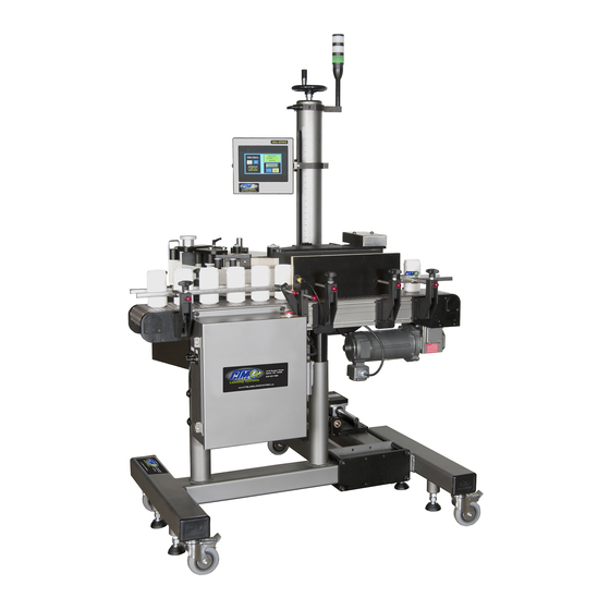
- Page 1 1318 QUAKER CIRCLE P.O. BOX 589 SALEM, OHIO 44460 PHONE: 330-332-1800 FAX: 330-332-2144 www.ctmlabelingsystems.com Designers and Manufacturers of Pressure Sensitive Labeling Equipment and Custom Product Handling 360a LABEL APPLICATOR CE VERSION MAINTENANCE & SERVICE MANUAL REVISION 360a-4a.1.X.XXX...
-
Page 2: Ec Declaration Of Conformity
Directive 2006/42/EC of the European Parliament and of the Council of 17 May 2006 on the approximation of the laws of the Member States relating to Machinery Manufacturer: CTM LABELING SYSTEMS 1318 Quaker Circle, Salem, Ohio 44460 USA Machine Name: 360a Series Label Applicator Model Number: 360a Serial Number: 360a-CE-0101-0809 Drawing Identification: ASS-200CE-0401, 1 Sheet, Rev. - Page 3 Testing Procedures The 360a-CE applicator was tested as a merge with the product detect sensor and display attached. Because of the many configurations and options that are available for this model, there was no way to test all configurations. The only issue with the different noses will be machine safety. The integration of an applicator into a product line may cause pinch points or other dangerous situations that will need guarded.
-
Page 4: Table Of Contents
TABLE OF CONTENTS TABLE OF CONTENTS INTRODUCTION ......................…...1 MACHINE TERMS ....................…...2 DISPLAY PANEL ....................…….…3 KEY TYPES…………………………………………………………………… 3-1 ALARMS……………………………………………………………………… CHANGING VALUES……………………………………………………..…. PASSWORD………………………………………………………………….… 3-4 MAIN MENU……………………………………………………………….…. SETUP MENUS (main setup) …………………………………………….…. LABEL SETUP………………………………………………………………... Label Length…………….……………………………… Label Stop…………………...…………………………… 3-6 Label Stop Compensation ...…………………………… Label Sensor………………………………………………... - Page 5 TABLE OF CONTENTS SPECIAL OPTIONS................…....3-29 Drive Parameters ……….………………………………... 3-29 Customer Password……….……………………………… 3-30 No Labels Found Count……..…………………………… 3-30 3-30 Software Version.…………………………………….… Placement To Time ……………………………………... 3-30 Missing Label Mode 2 ……………………………….…… 3-31 Auto Online Option………………………………………. 3-31 Product Detect Debounce Time…………………………… 3-31 Label Sensor Model………………………………………..
- Page 6 TABLE OF CONTENTS ACCESSORIES ......................…. 10 RECOMMENDED SPARE PARTS.................…. 11 CHANGEOVER INSTRUCTIONS ..............…… 12 APPLICATOR CHANGEOVER ……………………………………………… 12-1 BLOW BOX NOSE ASSEMBLY REMOVAL / INSTALLATION ………… 12-3 MERGE NOSE ASSEMBLY REMOVAL / INSTALLATION ……………… 12-4 TAMP NOSE ASSEMBLY REMOVAL / INSTALLATION ………………… 12-5 NOSE ASSEMBLY CHANGEOVER …………………………………………...
-
Page 7: Introduction
The CTM Labeling Systems’ 360a Series Modular Labeling System is unique in that the Main Module can be adapted to three different types of Applicators: Air Blow, Merge, or Tamp by changing the Nose Assembly. - Page 8 Applicator malfunction is possible, most problems happen because the Applicator is not setup correctly. If the Applicator doesn’t operate correctly, back up and start over. FOLLOW ALL SAFETY INSTRUCTIONS. The CTM 360a Series MLS applicator has been provided with a number of safety features. Observe all safety warnings and under no circumstances attempt to...
-
Page 9: Machine Terms
MACHINE TERMS DEFINITION OF MACHINE TERMS AIR BLAST JETS: The flexible Air Blast Jets press-fit into the inside face of the Blow Box Grid and can be re-arranged to provide an air stream pattern that transfers labels of various sizes and shapes to the product. The Air Jets are connected via a Manifold to the output of the “Air Blast”... - Page 10 MACHINE TERMS APPLICATOR DAT NOSE: The DAT (Dual Action Tamp) Applicator Nose is used for dispensing labels via an air blast to the side of the product with a tamping action and the leading or trailing panel of the same product with a swing action. SWING ONLY and SIDE ONLY operating modes are supported as well.
- Page 11 MACHINE TERMS LABEL TENSION BRUSH ASSEMBLY: This is an adjustable Brush to help create tension on the label liner. The Brush can be released while threading the label liner. NIP ROLLER: The spring-loaded Nip Roller provides positive pressure to the label liner that passes between the Drive and Nip Roller Assemblies.
- Page 12 MACHINE TERMS UNWIND ASSEMBLY: The roll of labels is placed on the Unwind Assembly for dispensing onto the product. The Unwind Block is used to mount the Unwind Assembly to the Main Module. The Unwind Assembly can be removed and remounted on the opposite side of the Module for easy conversion from a right-hand to a left-hand Applicator or vice versa.
- Page 13 360a DISPLAY 360a TOUCH SCREEN DISPLAY The following description provides general information about the Display and will tell the operator how to change values, explain the meaning of different screens, and describe the different options and how to set them up. TYPES OF KEYS are “go to”...
-
Page 14: Alarms
360a DISPLAY ALARMS There are two types of alarms generated in the 360a Applicator: Warning Alarm Critical Alarm Warning Alarm Status Box Critical Alarm Screen Warning Alarms will appear in the upper right hand corner of the Main Menu in the Status Box. Since these alarms are not serious, the Applicator will not be stopped. -
Page 15: Changing Values
360a DISPLAY ALARMS cont’d) (WARNING ALARMS) Label Placement is Too Low – This alarm occurs in Encoder-Based applications when the Label Placement distance is too small for encoder compensation to work correctly. During label placement a speed dependent distance is subtracted from the label placement value to properly position the label. If this alarm occurs, move the Product Detect Sensor upstream more, decrease the conveyor speed, or increase the Label Placement value. -
Page 16: Password
360a DISPLAY PASSWORD The Setup Section of the Display is password protected. The Standard 360a password is “1800”. When you get to a password-protected area, a screen similar to the one to the left will appear. This screen notifies the operator that the area is password protected. -
Page 17: Main Menu
360a DISPLAY MAIN MENU The Main Menu is divided into three sections. The upper right corner of the Display is a Status Window. The purpose of this box is to inform the operator of the status of the Applicator. The display shown to the left appears immediately after going offline. -
Page 18: Label Setup
360a DISPLAY LABEL SETUP The Label Setup menu is accessed from the Setup Menu by pressing the Label Setup Key. The label setup section gives the operator access to variables on the Applicator that pertain to the label. The following items may be changed in this section: Label Stop Label Length... - Page 19 360a DISPLAY LABEL SETUP (cont’d) Label Sensor -Pressing this key will bring up the Label Sensor Menu. This is where the sensitivity of the Label Sensor is setup. The operator will have two choices: Auto Teach Manual Teach Manual Teach In the Manual Teach Mode, the operator will first choose whether they want to trigger on the leading or trailing edge of the label.
-
Page 20: Label Formats
360a DISPLAY LABEL SETUP (cont’d) Label Formats This section allows the operator to save and load configuration setups for up to (48) different products and labels. This is useful if a customer is running several different products or labels over and over. Note: The Label Format Key at the Main Menu only allows the operator to only load Formats. - Page 21 360a DISPLAY LABEL SETUP (cont’d) Viewing/Loading a Format When the operator wants to view/load a Format File, they need to press the yellow portion of the key associated with the desired Format name. If the number is “0000”, no Format is saved in that location. Selecting a “0000”...
-
Page 22: Applicator Setup
360a DISPLAY APPLICATOR SETUP The Applicator Setup Menu is accessed from the Setup Menu by pressing the “Applicator Setup” Key. The screen is split into upper and lower sections. The upper part does not change and allows the operator to return to the Main or Setup Menus and place the Applicator on or offline. - Page 23 360a DISPLAY APPLICATOR SETUP (cont’d) Over Speed – The Over Speed Option allows a Merge Applicator to get up to Web Speed faster by dispensing the “Pre-Apply Feed” distance at the (Pre-Apply Speed % x Web Speed). In Multi-Label mode, this will help place the labels closer together.
-
Page 24: Label Profile
360a DISPLAY APPLICATOR SETUP (cont’d) (LABEL PROFILE) (Profile Screen) (Profile Help Screen) Note: The Help Screen will note Options that are incompatible with the Profiling Option. Profile Variables Rise Area -This is the distance the label travels before changing to the mid-product labeling speed. Enter a value between 0.1 and 20. - Page 25 360a DISPLAY APPLICATOR SETUP (cont’d) (LABEL PROFILE) Estimating Rise and Flat Areas This process will give you a starting point for setting Profile Variables. Some experimentation is necessary for best results. The example shown is for a convex or oval product. Apply a label by hand to the product.
- Page 26 360a DISPLAY APPLICATOR SETUP (cont’d) (LABEL PROFILE) Rise Area and Flat Area Final Adjustment The system will work best with the smallest Rise Area value and the largest Flat Area value that properly applies the label. Use the instructions below to find these values. With the Applicator online, send several products down the conveyor and observe the labels that are applied.
-
Page 27: Multi-Panel
360a DISPLAY APPLICATOR SETUP (cont’d) Multi-Panel Apply The Multi-Panel Apply Option is used to merge a label onto two or three panels of a product. An example might include the leading, top, and bottom panels of a clamshell container. The Applicator is initially setup so that the label is flagged out in front of the product but is still supported on the liner. - Page 28 360a DISPLAY APPLICATOR SETUP (cont’d) (MULTI-PANEL OPTION) (Multi-Panel Screen) (Multi-Panel Help Screen) Note: The Help Screen will note Options that are disabled when this Option is turned on. Configuring Multi-Panel Apply With Auto Setup Make sure the Applicator is powered up and offline. Perform the Encoder Setup procedure outlined in the Product Setup section.
-
Page 29: Product Setup
360a DISPLAY APPLICATOR SETUP (cont’d) (MULTI-PANEL OPTION) While in “LABEL SETUP” enter the Label Length measured for dimension B. Under “APPLICATOR SETUP”, press the “MULTI-PANEL” button and turn the Option on. Set the Short Feed to the distance measured for dimension E. Enter the distance after the label is dispensed to when the product clears the Peel Edge into the Product Clearance box. - Page 30 360a DISPLAY PRODUCT SETUP (cont’d) (ENCODER OPTION) The Applicator has a differential quadrature incremental encoder interface with times four interpolation built into the controller board. The Encoder Connector, located on the rear panel, has 5 VDC supply to power the Encoder. The Encoder wiring diagram and pin-out information appear in the drawings section in this manual and should be consulted for user supplied encoders.
- Page 31 360a DISPLAY PRODUCT SETUP (cont’d) (ENCODER OPTION) Compensation - Compensation is a number that functions within a formula to reduce the Label Placement value based on the encoder velocity. When products move faster on the conveyor, the label dispense must begin sooner to compensate for the acceleration time of the label to the product.
-
Page 32: Configuration
360a DISPLAY CONFIGURATION SETUP The Configuration Setup Menu is accessed from the Setup Menu by pressing the “Config Menu” key with the Applicator offline. The Configuration Menu provides access to Applicator: Type Setup, Options, Motion Parameters, Diagnostics, and the Label Sensor reset function. -
Page 33: Applicator Options
360a DISPLAY CONFIGURATION SETUP (cont’d) (APPLICATOR OPTIONS) Loose Loop - The Loose Loop Option allows labels to be printed and applied from one system by integrating a thermal printer into the web path of the Applicator. As the labels exit the printer, they go around a dancer arm to maintain web tension. -
Page 34: Crossover
360a DISPLAY CONFIGURATION SETUP (cont’d) (APPLICATOR OPTIONS) Crossover – The Crossover Option allows for “zero downtime” operation by interconnecting two (2) Applicators. Both Applicators are placed on the conveyor system one (1) upstream of the other. The upstream Applicator is the “Primary” labeler while the downstream applicator is the “Secondary” labeler. The Crossover routine has changed after 360a-2c.0.031 program version. - Page 35 360a DISPLAY CONFIGURATION SETUP (cont’d) (CROSSOVER OPTION) The Secondary has a new button that if this Applicator is active, you can transfer the labeling back to the Primary with less chance of missing products. Pressing this button will start the Primary labeling (if it is online) and after the Off Distance, the Secondary stops.
-
Page 36: Multi-Label
360a DISPLAY CONFIGURATION SETUP (cont’d) (APPLICATOR OPTIONS) Multi-Label – The Applicator has the ability to apply multiple labels per Product Detect Signal. The Number of Labels and the Center-to-Center Distance between the labels are configured in the Multi-Label Submenu. When the Applicator is online and a product moves in front of it, the Applicator receives a Product Detect Signal from the Sensor. -
Page 37: Powered Rewind
360a DISPLAY CONFIGURATION SETUP (cont’d) (MISSING LABEL OPTION) Missing Label Mode 2 The Missing Label Option has two (2) Modes of Operation. If the Applicator Type is set to either Air Blow or Tamp (N or I) and the Missing Label Option is turned ON in the Missing Label Submenu, the operator can enter the Special Options Menu, see page 3-29, where they can select Mode 2. -
Page 38: Foldover
360a DISPLAY CONFIGURATION SETUP (cont’d) (APPLICATOR OPTIONS) Skip Count – If it is desired, the Applicator can be setup to label every “x” product. If turned on, the Applicator will label the first product after going online and skip the next “x- 1”... -
Page 39: Label On Pad
360a DISPLAY CONFIGURATION SETUP (cont’d) (APPLICATOR OPTIONS) Label On Pad Option – The Label On Pad Option cannot be enabled if the Applicator Type is set to Merge. With the proper Vacuum Switch Sensor Assembly installed in the Applicator, the Label On Pad Output will match the current state of the Vacuum Switch Sensor while the Blow Valve is not active. -
Page 40: Max And Slew Speeds
360a DISPLAY CONFIGURATION SETUP (cont’d) Max And Slew Speeds -The Web Speeds Menu allows access to the Max and Slew Speed values for the Applicator. Other Motion Parameters (such as Accel and Decel) are accessed thru the Special Options Menu. Slew Speed –This is the Web Speed value used to move a label to the Peel Edge during a missing label feed. -
Page 41: I/O Diagnostic
360a DISPLAY CONFIGURATION SETUP (cont’d) There are other areas where Max Speed may have to be adjusted and that is if Profiling or Over Speed Options are used. If Max Speed is exceeded in those circumstances, a warning message will occur in the Status Box. -
Page 42: Special Options
360a DISPLAY SPECIAL OPTIONS SECTION (cont’d) The inertia of the label roll and the system components, friction, and dancer arm spring tension are all factors in determining how much torque is required to operate at a given Web Speed and Acceleration/Deceleration rate. -
Page 43: Auto Online Option
360a DISPLAY SPECIAL OPTIONS SECTION (cont’d) Missing Label Mode – This Option only appears if the Applicator Type is set to Air Blow or Tamp, Normal or Inverted, and the Missing Label Option is turned on in the Applicator Options Menu (pg. 3-24). Turning the Missing Label Option in the Applicator Options Menu only turns Mode 1 on. -
Page 44: Label Sensor Model
360a DISPLAY SPECIAL OPTIONS SECTION (cont’d) Label Sensor Model – Prior to spring 2016, the 360a Applicator used the Banner D10DNFP, referred to as D10, Sensor for the standard Label Sensor. In 2016, we began using the Banner DF-G3-ND-2M, referred to as DF-G3, as a replacement. -
Page 45: Factory Default
360a DISPLAY FACTORY DEFAULT The ability to reset to factory defaults is useful when the Applicator will not dispense labels due to a configuration problem. Resetting to factory defaults will bring all of the settings to something that works and adjustments can be made from there. It will also reset the label sensor to its factory default values. One of the first things an operator should do after resetting to default values is to teach the Label Sensor. -
Page 46: Rear Panel
REAR PANEL REAR PANEL CONNECTORS VALVE: When using a Tamp, Blow Box, or a Merge Applicator with an Imprinter, a Valve Bank is mounted to the side of the Applicator. This plug is used to power the Valves and will drive up to four (4) Valves with the standard Harness. ENCODER: The Encoder is connected to this plug. - Page 47 GENERAL SETUP PROCEDURES 360a SERIES SETUP PROCEDURES...
-
Page 48: Moving The Applicator
GENERAL SETUP PROCEDURES DISCONNECT THE AIR AND POWER FROM THE MACHINE BEFORE YOU PROCEDE! Moving the Applicator The applicator is made to be mounted from its U-arm. The U-arm is a “U” shaped welded steel bar that is attached to both sides of the applicator. Removing the (2) ¼ SHCS that help lock the applicator in place and loosening the (2) ½... -
Page 49: Job Setup
GENERAL SETUP PROCEDURES DISCONNECT THE AIR AND POWER FROM THE MACHINE BEFORE YOU PROCEDE! JOB SETUP NOTE: When reading through this section of the Manual, refer to section 14 for web path diagrams. THREADING LABELS With the power off remove the Outer Unwind Disk. Make sure the inside of the Inner Un wind Disk is at least 1 1/4”... -
Page 50: Label Sensor Setup
GENERAL SETUP PROCEDURES LABEL SENSOR SETUP The Label Sensor is a “U”-shaped Optical Sensor that is connected to the sensor electronics with Fiber Optic Cable. To insure proper operation of the Label Sensor, there should be no sharp bends in the Fiber Optic Cable from the Sensor to the Applicator Housing. -
Page 51: Label Length Setup
GENERAL SETUP PROCEDURES LABEL LENGTH SETUP Measure the distance from the leading edge of one label to the leading edge of the next. This will be the “Label Length” value. From the LABEL SETUP Menu change the Label Length. You may refer to page 3-6 for more details on Label Length and to page 3-3 for changing variables. -
Page 52: Label Stop Setup
GENERAL SETUP PROCEDURES LABEL STOP The Label Stop value is the distance from the label edge to the Label Sensor. Allowed values are between 0.001” and (Label Length – 0.06”). NOTE: Any value less than .06 may cause the Label Stop to move when the web speed changes. Press the “LABEL STOP”... -
Page 53: Label Static Test
GENERAL SETUP PROCEDURES LABEL STATIC TEST It’s important to know if the Applicator can consistently place labels in the same place over and over on the product. Without knowing this, you will not know whether label placement problems that occur on the line are due to the Applicator or to the product being labeled. -
Page 54: Labeler Type Setup
LABELER TYPE SETUP PROCEDURE MERGE APPLICATOR SETUP The Merge Applicator is used to apply labels to products moving on a conveyor. A label is fed onto the surface of the product at the same speed that the product is moving. Under Applicator Type in the Configuration Menu on the Display, select “MERGE”... -
Page 55: Air Blow Applicator
LABELER TYPE SETUP PROCEDURE AIR BLOW APPLICATOR SETUP The Air Blow Applicator is a versatile labeler in the sense that many different label sizes can be used without buying a new Pad or Manifold. Products can also be labeled at a stand still without contact. - Page 56 LABELER TYPE SETUP PROCEDURE AIR BLOW APPLICATOR SETUP (cont’d) AIR BLOW LABEL STOP With the Applicator online, jog a couple of labels. Label Stop position should be 1/32” from the Peel Edge Tip. If needed, change the Label Stop value. (Refer to Label Stop setup in the Display Section or page 3-6) AIR BLOW GRID SETUP...
- Page 57 LABELER TYPE SETUP PROCEDURE AIR BLOW APPLICATOR SETUP (cont’d) AIR BLOW AIR ASSIST The Air Assist Tube blows a stream of air onto the label to force it up against the Blow Box Grid during the label feed. The Air Assist starts to blow when the web starts to move and stops when the label is on the Grid.
-
Page 58: Tamp Applicator
LABELER TYPE SETUP PROCEDURE TAMP APPLICATOR SETUP The Tamp Applicator consists of a Tamp Slide, Label Manifold, and a Label Pad. The label is fed out onto the Label Pad and is tamped within 1/8” of the labeling surface. The label is then blown off by an air blast. The Tamp Applicator has higher placement accuracy and is less dependent on product movement. - Page 59 LABELER TYPE SETUP PROCEDURE TAMP APPLICATOR SETUP (cont’d) TAMP PEEL EDGE ALIGNMENT Turn the power on, move the Tamp Assembly up and make sure the Applicator is offline. Advance the web using the Drive Roller. Stop when half of the label is off the Peel Edge Tip.
- Page 60 LABELER TYPE SETUP PROCEDURE TAMP APPLICATOR SETUP (cont’d) TAMP AIR ASSIST The Air Assist Tube blows a stream of air onto the label to force it up against the Tamp Pad during the label feed. The air assist starts to blow when the web starts to move and stops when the label is on the Pad. The Extended Air Assist Time allows the air assist to blow after the label feed to help stabilize the label.
- Page 61 LABELER TYPE SETUP PROCEDURE TAMP APPLICATOR SETUP (cont’d) TAMP SLIDE The Tamp Slide is used to move the Label Pad and Manifold toward the product. The speed at which it travels is a function of air pressure and airflow. The Valve and Regulator for the Tamp Assembly is part of the Valve Bank mounted to the side of the Applicator.
-
Page 62: Dual Action Tamp (Dat)
LABELER TYPE SETUP PROCEDURE DUAL ACTION TAMP (DAT) SETUP DAT: LEADING EDGE SEQUENCE (SWING & TAMP) With the Applicator ONLINE and a label on the Pad, the labeler receives a Product Detect Signal. After waiting the Label Placement Distance or Time, the Label Pad swings out in front of the product. At the end of the Swing Extend Time, the Air Blast Valve turns on to apply a label to the leading panel of the product, the Swing Arm starts to return home, and the Swing Retract Timer is started. - Page 63 LABELER TYPE SETUP PROCEDURE DUAL ACTION TAMP (DAT) SETUP (cont’d) LABEL PLACEMENT When the Applicator is set to DAT, a Second Label Placement Value appears in the Main and Product Setup Menus. The First Placement Value corresponds to the first Tamp Action while the Second Placement Value corresponds to the Second Tamp Action.
- Page 64 LABELER TYPE SETUP PROCEDURE DUAL ACTION TAMP (DAT) SETUP (cont’d) DAT GENERAL SETUP PROCEDURES 1) The Label Stop must be properly set for the Applicator to work correctly. Adjust the Label Stop Value to position the label at or slightly back from the Peel Edge. 2) Tamp height should be adjusted so that the label feeds out in contact with the Label Pad.
- Page 65 LABELER TYPE SETUP PROCEDURE DUAL ACTION TAMP (DAT) SETUP (cont’d) DAT SHOCK ABSORBERS AND FLOW CONTROLS Both the Linear and Rotary Actuators have Shock Absorbers that need to be adjusted. The Swing Home Shock has a Stop Collar installed. This Collar should be adjusted to provide 1/8” of shock travel. To adjust the Shock so the Swing Arm stops in the right position, press the Manual Override on the Rotary Actuator Valve and watch the movement of the Swing Arm.
- Page 66 LABELER TYPE SETUP PROCEDURE DUAL ACTION TAMP (DAT) SETUP (cont’d) POSITIONING THE APPLICATOR The product must be presented to the Applicator in a consistent manner. Label accuracy cannot be maintained if the surface being labeled changes speed or distance relative to the Label Pad. NOTE: The following directions are for the DAT Applicator.
-
Page 67: Product Setup
PRODUCT SETUP PROCEDURE PRODUCT SETUP The Applicator should be setup and have successfully passed the static test before continuing with this section. If you have skipped the Applicator Setup Section and have trouble with the application here, it will leave you with more areas to troubleshoot while fixing the problem. Regardless of which type of Applicator Nose you are using, it is important to control the product prior to labeling. -
Page 68: Label Placement
PRODUCT SETUP PROCEDURE OPTIONAL PRODUCT SENSOR SETUP (Banner S18SN6FF50) This Sensor is an 18mm barrel type with a 50mm far limit cut-off. This means it will see objects that are less than 2” away and ignore the rest. There is nothing to adjust on the sensor except the physical position. -
Page 69: Encoder
PRODUCT SETUP PROCEDURE ENCODER SETUP Adding an Encoder to the Applicator is a good way to handle products that are varying in speed. If setup properly, the Applicator will compensate the Label Placement position for all Applicator Types. In Merge Applications, the Encoder accounts for product speed changes during the label dispense to insure good labeling performance. -
Page 70: General Maintenance
GENENRAL MAINTENANCE 360a SERIES GENERAL MAINTENANCE PROCEDURES... -
Page 71: Daily
GENENRAL MAINTENANCE MAINTENANCE NOTE: Since all three types of Applicator are covered in this Section, some items discussed will not pertain to your application. DAILY MAINTENANCE Examine the Peel Edge, Blow Box Grid, Label Pad and Rollers for excessive adhesive build-up. If necessary, clean these surfaces with alcohol or similar solvent. -
Page 72: Semi-Annual
GENENRAL MAINTENANCE SEMI-ANNUAL MAINTENANCE Replace the Air Inlet Filter and clean Collection Bowl. Clean inside and outside of Applicator using an industrial vacuum cleaner. NOTE: Do not use compressed air to blow dust off of the electrical section of the Applicator. Replace Slip Clutch Disk. -
Page 73: Rewind Slip Clutch
GENENRAL MAINTENANCE DISCONNECT THE AIR AND POWER FROM THE MACHINE BEFORE YOU PROCEDE! REWIND SLIP CLUTCH ADJUSTMENT More or less tension may be needed on the Rewind if the liner is being wound too loose or tight. Different conditions will warrant this adjustment: Change in label width or length. -
Page 74: Drive Belt Adjustment
GENENRAL MAINTENANCE DISCONNECT THE AIR AND POWER FROM THE MACHINE BEFORE YOU PROCEDE! DRIVE BELT ADJUSTMENT Remove all AC power and air to the Applicator. Remove the lower stainless Cover. Rotate the 360a so the Drive Roll Assembly is facing the floor. This orientation will aid you when it comes time to set angular alignment. -
Page 75: Troubleshooting
TROUBLESHOOTING PROBLEM POSSIBLE CAUSE SOLUTION WITH THE POWER SWITCH ON, POWER CORD DEFECTIVE OR UNPLUGGED INSPECT AND CORRECT NO COOLING FAN; NO DISPLAY AC FUSE BLOWN DETERMINE CAUSE AND REPLACE FUSE WITH THE POWER SWITCH ON, DISPLAY CABLE NOT PLUGGED IN TO RECONNECT CABLE COOLING FAN ON;... - Page 76 TROUBLESHOOTING PROBLEM POSSIBLE CAUSE SOLUTION LABEL DOES NOT ADVANCE NIP ROLLER NOT ENGAGED INSPECT AND CORRECT WHEN THE APPLICATOR IS AGAINST DRIVE ROLLER ONLINE AND JOG IS PRESSED DRIVE BELT IS BROKEN REPLACE BELT LOST KEY IN DRIVE PULLEY FOLLOW PROCEDURE FOR SLIP CLUTCH ADJUSTMENT.
- Page 77 TROUBLESHOOTING PROBLEM POSSIBLE CAUSE SOLUTION LABEL LINER NOT WINDING UP REWIND SLIP CLUTCH NEEDS SEE SLIP CLUTCH ADJUSTMENT TENSIONING OR REPLACED IN THE MAINTENANCE SECTION ONE-WAY CLUTCH BEARING REPLACE REWIND SHAFT ASSEMBLY NOT WORKING BROKEN BELT REPLACE BELT LABELS ARE NOT HELD ON LABEL AIR BLOW CHECK FOR BLOWN FUSE GRID OR LABEL PAD...
- Page 78 TROUBLESHOOTING PROBLEM POSSIBLE CAUSE SOLUTION LABEL PLACEMENT ON GRID OR AIR BLOW YOU MAY HAVE TO MASK OFF LABEL PAD NOT CONSISTENT IMPROPER VACUUM THE HOLES NOT USED BY THE LABEL ON THE INSIDE OF THE VACUUM BOX YOU CAN ADD MORE VACUUM BY TURNING THE VAC SWITCH TO HIGH TAMP ADJUST AIR PRESSURE...
-
Page 79: Display Faults
TROUBLESHOOTING DISPLAY FAULTS The Operator Interface will display Warnings and Alarms that pertain to the application. The following are screens that will help diagnose a Drive or Display problem that is more serious in nature than the standard Alarms. DRIVE FAULT The Drive Fault screen will list four (4) things that will stop the Applicator from running when they occur. - Page 80 TROUBLESHOOTING CLEARED DISPLAY VARIABLES At power up, the Applicator’s Controller sends all of the system variables to the Display. While the Applicator is powered, the Controller looks to see if the Display variables have changed. If for some reason the variables are reset to zero, a Warning Screen is displayed indicating that the Display has lost its variables.
-
Page 81: Accessories
ACCESSORIES ACCESSORIES The following is only a partial list of Accessories available for the 360a Applicator. ELECTRONIC CROSSOVER The Electronic Crossover or “Zero Downtime” Accessory is an electronic interface between two labeling Applicators positioned in series on a conveyor system. The Crossover System monitors the Primary Applicator’s Fault conditions and switches to a Secondary Applicator to prevent interruption of production flow. - Page 82 Please contact the factory for details and availability. SNORKELS CTM has a large variety of Snorkel options to place the Applicator Nose close to the labeling operation while the Applicator’s body remains farther away. Consult the factory to match a solution to your requirements.
-
Page 83: Recommended Spare Parts
360a APPLICATOR SPARE PARTS LIST When Ordering parts, present Serial Number of 360a 360a Series Core Unit Spare Parts List RECOMMENDED TOOL Part Number Recommended Qty Description PE-TE6000 ENTRELEC WIRING TOOL WEAR ITEMS Part Number Recommended Qty Description MP-200-0235 NIP ROLLER LIFT CAM... - Page 84 360a APPLICATOR SPARE PARTS LIST When Ordering parts, present Serial Number of 360a NON-POWERED UNWIND ASSEMBLY SPARE PARTS LIST WEAR ITEMS Part Number Recommended Qty Description PM-OR1007 O-RING RECOMMENDED SPARE PARTS (12" NON-POWERED UNWIND) Part Number Recommended Qty Description SAS-200-0131 or 5"...
- Page 85 360a APPLICATOR SPARE PARTS LIST When Ordering parts, present Serial Number of 360a NON-POWERED UNWIND with POWERED REWIND SPARE PARTS LIST (not CE approved) WEAR ITEMS Part Number Recommended Qty Description PM-OR1040 CLEAR O-RING RECOMMENDED SPARE PARTS (16" & 20" NON-POWERED with POWERED REWIND) Part Number Recommended Qty Description...
- Page 86 360a APPLICATOR SPARE PARTS LIST When Ordering parts, present Serial Number of 360a MERGE SPARE PARTS LIST WEAR ITEM Part Number Recommended Qty Description PM-T1000 or UHMW TAPE FOR 5" PEEL EDGE ( 5 7/16" Wide x 7" Lg.) PM-T1015 UHMW TAPE FOR 7.5"...
- Page 87 360a APPLICATOR SPARE PARTS LIST When Ordering parts, present Serial Number of 360a AIR BLOW SPARE PARTS LIST WEAR ITEM Part Number Recommended Qty Description PM-T1010 or UHMW TAPE FOR 5" PEEL EDGE (6" Wide x 4" Lg.) PM-T1015 UHMW TAPE FOR 7.5" PEEL EDGE (8" Wide x 4" Lg.) ASS-211-0113 AIR TUBE ASSEMBLY ASS-211-0113E...
- Page 88 360a APPLICATOR SPARE PARTS LIST When Ordering parts, present Serial Number of 360a RVB SPARE PARTS LIST WEAR ITEM Part Number Recommended Qty Description PM-T1010 or UHMW TAPE FOR 5" PEEL EDGE ( 6" Wide x 4" Lg.) PM-T1015 UHMW TAPE FOR 7.5" PEEL EDGE (8" Wide x 4" Lg.) ASS-215-0110X-X or 5"...
- Page 89 360a APPLICATOR SPARE PARTS LIST When Ordering parts, present Serial Number of 360a TAMP SPARE PARTS LIST WEAR ITEM Recommended Qty Part Number Description PM-T1010 or UHMW TAPE FOR 5" PEEL EDGE (6" Wide x 4" Lg.) PM-T1015 UHMW TAPE FOR 7.5" PEEL EDGE (8" Wide x 4" Lg.) PM-T1010 UHMW TAPE FOR 10"...
- Page 90 360a APPLICATOR SPARE PARTS LIST When Ordering parts, present Serial Number of 360a SWING TAMP SPARE PARTS LIST WEAR ITEM Recommended Qty Part Number Description PM-T1010 or UHMW TAPE FOR 5" PEEL EDGE (6" Wide x 4" Lg.) PM-T1015 UHMW TAPE FOR 7.5" PEEL EDGE (8" Wide x 4" Lg.) ASS-215-0110X-X or 5"...
- Page 91 360a APPLICATOR SPARE PARTS LIST When ordering parts, present Serial Number of 360a DUAL ACTION TAMP SPARE PARTS LIST WEAR ITEM Recommended Qty Part Number Description PM-T1010 or UHMW TAPE FOR 5" PEEL EDGE (6" Wide x 4" Lg.) PM-T1015 UHMW TAPE FOR 7.5"...
- Page 92 360a APPLICATOR SPARE PARTS LIST When ordering parts, present Serial Number of 360a 360a OPTIONS SPARE PARTS LIST OPTIONS: RECOMMENDED SPARE PARTS (LOW LABEL, WEB BREAK ALARMS) Part Number Recommended Qty Description PE-LI1088 RED,YELLOW,GREEN LED ALARM LIGHT (BANNER) ASS-200-0422 LOW LABEL SENSOR (w/o BRACKET) ASS-200-0423 END OF WEB SENSOR (w/o BRACKET) OPTIONS: RECOMMENDED SPARE PARTS (TAMP HOME SENSOR)
- Page 93 360a APPLICATOR SPARE PARTS LIST When Ordering parts, present Serial Number of 360a RETIRED UNWIND & REWIND SPARE PARTS LIST RECOMMENDED SPARE PARTS (16" & 20" NON-POWERED with POWERED REWIND w/DANCER) Part Number Recommended Qty Description PM-BE1238 #R4 BALL BEARING ASS-200-0460 PROXIMITY SWITCH SAS-211-0120...
-
Page 94: Changeover Instructions
CHANGEOVER INSTRUCTIONS CHANGING TO OPPOSITE HAND DISPENSE When performing an applicator changeover, the nose assembly, unwind assembly, rewind, and wiring are first changed to the opposite hand dispense. Then each component assembly is remounted on the opposite side of the applicator. The symmetry of the applicator main module and the individual parts facilitate the changeover process but it can be confusing if care is not exercised. -
Page 95: Blow Box Nose Assembly Removal / Installation
CHANGEOVER INSTRUCTIONS NOSE ASSEMBLY REMOVAL AND INSTALLATION INSTRUCTIONS NOTE: DISCONNECT THE POWER CORD AND AIR SUPPLY FROM THE MACHINE BEFORE ATTEMPTING ANY OF THE FOLLOWING PROCEDURES. FAILURE TO FOLLOW THIS PRECAUTION COULD RESULT IN INJURIES FROM MOVING PARTS OR ELECTRICAL SHOCK! BLOW BOX NOSE ASSEMBLY REMOVAL 1) Remove the stainless steel cover from the bottom of the applicator. -
Page 96: Merge Nose Assembly Removal / Installation
CHANGEOVER INSTRUCTIONS NOTE: DISCONNECT THE POWER CORD AND AIR SUPPLY FROM THE MACHINE BEFORE ATTEMPTING ANY OF THE FOLLOWING PROCEDURES. FAILURE TO FOLLOW THIS PRECAUTION COULD RESULT IN INJURIES FROM MOVING PARTS OR ELECTRICAL SHOCK! MERGE NOSE ASSEMBLY REMOVAL 1) Remove the stainless steel cover on the bottom of the applicator. 2) Remove the air tubes interconnecting the two sides of the applicator. -
Page 97: Tamp Nose Assembly Removal / Installation
CHANGEOVER INSTRUCTIONS NOTE: DISCONNECT THE POWER CORD AND AIR SUPPLY FROM THE MACHINE BEFORE ATTEMPTING ANY OF THE FOLLOWING PROCEDURES. FAILURE TO FOLLOW THIS PRECAUTION COULD RESULT IN INJURIES FROM MOVING PARTS OR ELECTRICAL SHOCK! TAMP NOSE ASSEMBLY REMOVAL 1) Remove the stainless steel cover from the bottom of the applicator. 2) Remove the air tubes interconnecting the two sides of the applicator. -
Page 98: Nose Assembly Changeover
CHANGEOVER INSTRUCTIONS NOSE ASSEMBLY CHANGEOVER When changing the nose assembly to the opposite hand dispense, all parts are first transferred to the opposite side of the mounting plate. Then the entire nose assembly is rotated 180 degrees and remounted to the opposite side of the applicator. - Page 99 CHANGEOVER INSTRUCTIONS BLOW BOX PEEL EDGE CHANGEOVER 1) Remove the label sensor from the peel edge assembly and remount on the opposite side making sure that the fiber cables are threaded through from the opposite side. The open end of the U-shaped sensor should face towards the inside.
-
Page 100: Tamp Peel Edge / Cylinder Changeover
CHANGEOVER INSTRUCTIONS TAMP PEEL EDGE CHANGEOVER 1) Remove the label sensor from the peel edge assembly and remount on the opposite side making sure that the fiber cables are threaded through the holes from the opposite side. The open end of the U- shaped sensor should face towards the inside. -
Page 101: Rewind Removal / Installation / Changeover
CHANGEOVER INSTRUCTIONS REWIND REMOVAL 1) Remove the belt connecting the rewind clutch to the motor. 2) Remove the rewind mandrel from its drive shaft. 3) Remove the six #10 screws that hold the rewind mounting plate to the housing. REWIND INSTALLATION 1) Attach the rewind mounting plate to the housing using the six #10 screws. -
Page 102: 360 Applicator Drawings
360 APPLICATOR DRAWINGS 360a SERIES CE MECHANICAL ELECTRICAL DRAWINGS 13-1...
Need help?
Do you have a question about the 360a series and is the answer not in the manual?
Questions and answers