Table of Contents
Advertisement
Quick Links
Advertisement
Table of Contents

Related Manuals for CTM 360 Series


Summary of Contents for CTM 360 Series
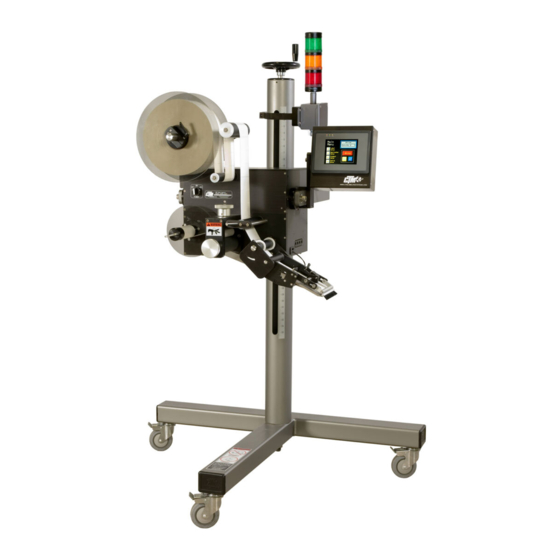
- Page 1 1318 QUAKER CIRCLE PO BOX 589 SALEM, OHIO 44460 PHONE: 330-332-1800 FAX: 330-332-2144 DESIGNERS AND MANUFACTURERS OF PRESSURE SENSITIVE LABELING EQUIPMENT AND CUSTOM PRODUCT HANDLING 360 SERIES LABEL APPLICATOR MAINTENANCE & SERVICE MANUAL REVISION 360-2c.10.1 050103...
-
Page 2: Table Of Contents
___________________ TABLE OF CONTENTS TABLE OF CONTENTS INTRODUCTION ......................…... 1 MACHINE TERMS ....................…... 4 DISPLAY PANEL ....................…….…8 MAIN MENU ………………………………………………………………………………………8 ONLINE …………………………………………………………………………………………….8 APPLICATOR TYPE …………………………………………………………………………….. 8 LABEL STOP ………………………………………………………………………………………9 LABEL SETUP …………………………………………………………………………………….9 HOME ……………………………………………………………………………………………..10 JOG ………………………………………………………………………………………………..10 WEB SPEED .........................……. 10 ALARM RESET ........................……….10 LABEL FORMATS......................…..….11 APPLICATOR OPTIONS ....................……….11... - Page 3 ___________________ TABLE OF CONTENTS CROSSOVER OPTION ..............………………… 46 SETUP …………………………………………………………………………………………….46 MONITORING ……………………………………………………………………………………47 PRECAUTIONS …………………………………………………………………………………..47 PRINTER SETUP ……………………………………………………………………... 49 LOOSE LOOP SETUP ....................…………….49 IMPRINTER SETUP ....................…………….49 LABEL OPTIONS …………………………………………………………………….. 51 MULTIPLE LABEL SETUP................…………..….. 51 MISSING LABEL …………………………………………………………………………...……52 SKIP COUNTER….………………………………………………………………………...……..53 CONFIGURATION MENU ….………………………………………………………. 55 RESET TO FACTORY DEFAULTS ……………………………………………………………..55 SPECIAL OPTIONS ………………………………………………………………………………55 WEB PATH DIAGRAMS ..……………………………………………………………...
- Page 4 ___________________ TABLE OF CONTENTS ACCESSORIES ......................…. 89 ELECTRONIC CROSSOVER ……………………………………………………………………89 IMPRINTER ………………………………………………………………………………………89 LOOSE LOOP …………………………………………………………………………………….89 LOW LABEL DETECTION ……………………………………………………………………...89 TAMP SWITCH …………………………………………………………………………………..89 WEB BREAK DETECTION ……………………………………………………………………...89 RECOMMENDED SPARE PARTS.................…. 91 AIR BLOW APPLICATOR .....................….. 92 MERGE APPLICATOR ......................…...93 TAMP APPLICATOR ......................…...94 DRAWINGS ...................…………………….
- Page 5 ___________________ TABLE OF CONTENTS (This page is intentionally blank.)
-
Page 6: Introduction
The CTM Integration 360 Series Modular Labeling System is unique in that the main module can be adapted to three different types of applicators: Air Blow, Merge, or Tamp by changing the nose assembly. - Page 7 If the applicator doesn’t operate correctly, back up and start over. FOLLOW ALL SAFETY INSTRUCTIONS. The CTM 360 Series MLS applicator has been provided with a number of safety features. Observe all safety warnings and under no circumstances attempt to...
- Page 8 ________________ INTRODUCTION (This page is intentionally blank.)
-
Page 9: Machine Terms
_________________ MACHINE TERMS DEFINITION OF MACHINE TERMS AIR BLAST JETS: The flexible air blast jets press-fit into the inside face of the vacuum grid and can be re-arranged to provide an air stream pattern that transfers labels of various sizes and shapes to the product. The air jets are connected via a manifold to the output of the “Air Blast”... - Page 10 _________________ MACHINE TERMS BLOW BOX / VACUUM GRID: The blow box/vacuum grid is the cube shaped assembly located next to the peel edge on a blow box applicator. Two axial fans mounted above the grid create the vacuum needed to hold the label in place prior to application.
- Page 11 _________________ MACHINE TERMS PEEL EDGE: The peel edge is the beveled plate located at the end of the applicator nose. When the label liner is pulled around the peel edge, the label separates from the liner and is transferred to the vacuum grid, tamp pad, or product depending on the applicator type.
- Page 12 _________________ MACHINE TERMS (This page is intentionally blank.)
-
Page 13: Display Panel
_______________ DISPLAY PANEL DISPLAY PANEL MAIN MENU: The main menu or home page screen displays the applicator type, whether it is in a left or right-handed configuration, and the label rate. ONLINE: The ONLINE function indicates whether or not the applicator is active. When the online LED is on, the applicator can be jogged or cycled from the product detect signal. -
Page 14: Label Stop
_______________ DISPLAY PANEL LABEL STOP: The label stop key lets you enter the label stop distance value. The label stop value is the distance from the label edge to the label sensor. If the entered value is incorrect, an out-of-range message is displayed and the label stop menu is re-displayed so that a different value may be entered. -
Page 15: Home
_______________ DISPLAY PANEL LEADING EDGE APPLY: The leading edge apply option is used to merge a label onto two or three panels of a product. An example might include the leading, top, and bottom panels of a CD case. The applicator is initially setup so that the label is flagged out in front of the product but is still supported on the liner. -
Page 16: Applicator Options
_______________ DISPLAY PANEL APPLICATOR OPTIONS: The applicator option menu will let you view and choose which options you’ll be using in a particular application. For example: If you have a loose loop configuration, simply select the loose loop option and press the HOME key to take you back to the main menu. -
Page 17: Label Placement
_______________ DISPLAY PANEL NOTE: If you press the applicator options key, the first screen shows all of the available options and which ones are currently active. Selecting a particular option for the first time requires a password. The password is 1800. Subsequent selections do not require a password as long as you remain within an option menu. -
Page 19: Rear Panel
_____________ REAR PANEL REAR PANEL CONNECTORS VALVE: When using a Tamp, Blow Box, or a Merge applicator with an imprinter, a valve bank is mounted to the side of the machine. This plug is used to power the valves. ENCODER: The encoder is connected to this plug. The encoder is enabled through the product setup menu. - Page 20 _____________ REAR PANEL (This page is intentionally blank.)
- Page 21 _______________________________ GENERAL SETUP PROCEDURES 360 SERIES SETUP PROCEDURES...
-
Page 22: Job Setup
_______________________________ GENERAL SETUP PROCEDURES !!CAUTION!! DISCONNECT THE AIR AND POWER FROM THE MACHINE BEFORE YOU THREAD LABELS OR YOU MAY BE CAUGHT BETWEEN THE DRIVE AND NIP ROLLERS IF THE MACHINE CYCLES UNEXPECTEDLY! JOB SETUP NOTE: When reading through this section of manual, refer to the web path diagram section. THREADING LABELS With the power off remove the outer unwind disk. -
Page 23: Label Sensor Setup
_______________________________ GENERAL SETUP PROCEDURES LABEL SENSOR SETUP The label sensor is a “U”-shaped optical sensor that is connected to the sensor electronics with fiber optic cable. To insure proper operation of the label sensor, there should be no sharp bends in the fiber optic cable from the sensor to the applicator housing. - Page 24 _______________________________ GENERAL SETUP PROCEDURES message is displayed indicating that the label stop may need adjusting. The operator may override the controller’s value using the “LABEL STOP” menu. MANUAL SETUP The manual setup function is provided for those instances where auto setup does not work. The following steps summarize the manual setup sequence: With the applicator offline, select “2”...
-
Page 25: Label Length Setup
_______________________________ GENERAL SETUP PROCEDURES LABEL LENGTH SETUP Measure the distance from the leading edge of one label to the leading edge of the next. This will be the “label length” value. From the LABEL SETUP menu press “3” to adjust the “LABEL LENGTH” value. Enter the length and press “ENTER”. -
Page 26: Label Stop Setup
_______________________________ GENERAL SETUP PROCEDURES LABEL STOP The label stop value is the distance from the label edge to the label sensor. Allowed values are between 0.03” and (label length – 0.06”). NOTE: After software version 360-2b.25 any value less than .06 comes with a warning that says the label stop can move when the web speed changes. -
Page 27: Web Speed Setup
_______________________________ GENERAL SETUP PROCEDURES LABEL FORMATS (cont.) Load Format This option will allow the operator to load the values of a previously stored format in to the system as current values. Pick “2” at the label format menu and select the number of the format you want to load. - Page 28 _______________________________ GENERAL SETUP PROCEDURES (This page is intentionally blank.)
-
Page 29: Merge Applicator
___________________________________ LABELER TYPE SETUP PROCEDURE MERGE APPLICATOR SETUP The merge applicator is used to apply labels to products moving on a conveyor. A label is feed onto the surface of the product at the same speed that the product is moving. On the display, under “APPLICATOR TYPE”... - Page 30 ___________________________________ LABELER TYPE SETUP PROCEDURE ENTERING LABEL PROFILING VALUES Press “LABEL SETUP” then select “LABEL PROFILING”. The label profiling menu shows the following three items: Profile Rise Area Profile Flat Area Web Ratio Press “1) PROFILE RISE AREA”. This is the distance the label travels before changing to the mid-product labeling speed.
- Page 31 ___________________________________ LABELER TYPE SETUP PROCEDURE ESTIMATING RISE AREA AND FLAT AREA This process will give you a starting point for profile variables. Some experimentation is necessary for best results. The example shown is for a convex or oval product. Apply a label by hand to the product. Measure the rise area by looking at the beginning of the label to where it starts to flatten out.
- Page 32 ___________________________________ LABELER TYPE SETUP PROCEDURE RISE AREA AND FLAT AREA FINAL ADJUSTMENT The system will work best with the smallest rise area value and the largest flat area value that properly applies the label. Use the instructions below to find these values. With the applicator online, send several products down the conveyor and observe the labels that are applied.
-
Page 33: Merge Leading Edge Apply
___________________________________ LABELER TYPE SETUP PROCEDURE MERGE LEADING EDGE APPLY The leading edge apply option is used to merge a label onto two or three panels of a product. An example might include the leading, top, and bottom panels of a CD case. The applicator is initially setup so that the label is flagged out in front of the product but is still supported on the liner. - Page 34 ___________________________________ LABELER TYPE SETUP PROCEDURE CONFIGURING LEADING EDGE APPLY WITH AUTO SETUP Make sure the applicator is powered and offline. Press “LABEL SETUP” and select “5) LEADING EDGE APPLY” Select “1) LEADING EDGE OPTION IS: ON” from the leading edge submenu. Select “3) PRODUCT CLEARANCE TIME / DISTANCE”...
-
Page 35: Air Blow Applicator
___________________________________ LABELER TYPE SETUP PROCEDURE AIR BLOW APPLICATOR SETUP The air blow applicator is a versatile labeler in the sense that many different label sizes can be used without buying a new pad or manifold. Products can also be labeled at a stand still without contact. The blow box consists of two axial fans mounted in the top of the assembly that produce the vacuum needed to hold the label. - Page 36 ___________________________________ LABELER TYPE SETUP PROCEDURE AIR BLOW PEEL EDGE ALIGNMENT Turn power on to the applicator and make sure it’s offline. Advance the web using the drive roller and notice how the label feeds onto the grid. A normal paper label should deflect 5-10 degrees to the bottom surface of the label grid. A stiffer label should feed straight onto the grid.
- Page 37 ___________________________________ LABELER TYPE SETUP PROCEDURE AIR BLOW AIR ASSIST The air assist tube blows a stream of air onto the label to force it up against the blow box grid during the label feed. The air assist starts to blow when the web starts to move and stops when the label is on the grid.
-
Page 38: Tamp Applicator
___________________________________ LABELER TYPE SETUP PROCEDURE TAMP APPLICATOR SETUP The tamp applicator consists of a tamp slide, label manifold, and a label pad. The label is fed out onto the label pad and is tamped within 1/8” of the labeling surface. The label is then blown off by an air blast. The tamp applicator has higher placement accuracy and is less dependent on product movement. - Page 39 ___________________________________ LABELER TYPE SETUP PROCEDURE TAMP LABEL STOP With the applicator online, jog a couple of labels. Label stop position should be 1/32” from the peel edge tip. If needed change the label stop value. (Refer to label stop setup in the general job setup) TAMP VACUUM The tamp vacuum is generated by a vacuum venturi located on the applicator.
- Page 40 ___________________________________ LABELER TYPE SETUP PROCEDURE TAMP AIR ASSIST The air assist tube blows a stream of air onto the label to force it up against the tamp pad during the label feed. The air assist starts to blow when the web starts to move and stops when the label is on the pad. The extended air assist time allows the air assist to blow after the label feed to help stabilize the label.
- Page 41 ___________________________________ LABELER TYPE SETUP PROCEDURE TAMP SLIDE The tamp slide is used to move the label pad and manifold toward the product. The speed at which it travels is a function of air pressure and airflow. The valve and regulator for the tamp assembly is part of the valve bank mounted to the side of the applicator.
- Page 42 ___________________________________ LABELER TYPE SETUP PROCEDURE (This page is intentionally blank.)
-
Page 43: Product Setup
_____________________________ PRODUCT SETUP PROCEDURE PRODUCT SENSOR The factory product sensor is a reflective type. Other types can be used but the following setup procedure is for a reflective sensor. Make sure the sensor is plugged into the applicator. Turn the power on and leave the applicator offline. Set the sensor to DO (dark operation) by gently turning the output select screw completely counter-clockwise. -
Page 44: Product Setup
_____________________________ PRODUCT SETUP PROCEDURE PRODUCT SETUP Make sure the power is on and the applicator is offline. Press “PRODUCT SETUP” on the display. The product setup screen will show the status of the detector lockout function, whether the encoder is on or off and its speed, the label counter value, and whether the product sensor is detecting a product or not. - Page 45 _____________________________ PRODUCT SETUP PROCEDURE LABEL PLACEMENT (cont’d) NOTE: 1) The applicator will be slower and less accurate for larger label placement values. Keep this value to a minimum by moving the product sensor closer to the peel edge. 2) If the encoder option is on, the label placement value is in inches. If the encoder is off, the label placement value is in seconds.
- Page 46 _____________________________ PRODUCT SETUP PROCEDURE (This page is intentionally blank.)
-
Page 47: Mounting
_____________ ENCODER SETUP ENCODER OPTION The encoder option is useful when the product velocity varies during the application cycle. An example of such an application is forms on a forms table. With the encoder installed and enabled, the labeler adjusts the label dispense speed to insure accurate label placement on the product. - Page 48 _____________ ENCODER SETUP ENCODER SETUP Select “ENCODER SETUP” at the product setup menu. NOTE: This area is password protected. The password is 1800. Going back to the home screen will disable the last password entry. Turn the encoder on by pressing “1”. NOTE: If the encoder was already enabled, you would turn off the encoder by pressing “1”.
- Page 49 _____________ ENCODER SETUP ENCODER SETUP (cont.) Rate Compensation for Air Blow and ITB Tamp Applicators: When selecting a value for rate compensation, start at 0.025. Apply labels to the product at a slower speed. Then run the product at production speeds or faster. If the labels are applied in the same place, the compensation is correct.
- Page 50 _____________ ENCODER SETUP (This page is intentionally blank.)
-
Page 51: Setup
_______________ CROSSOVER SETUP CROSSOVER OPTION The crossover option allows for “zero downtime” operation by interconnecting two applicators with identical setup configurations. Both applicators are placed on the conveyor system one upstream of the other. The upstream applicator is the “Primary” labeler while the downstream applicator is the “Secondary”... -
Page 52: Setup
_______________ CROSSOVER SETUP CROSSOVER MONITORING If the applicator is a secondary labeler, the crossover sub-menu will have a MONITOR SECONDARY SETUP selection. This menu is provided to aid the operator in setting up the crossover network and is particularly helpful if the secondary applicator is not labeling or is double labeling products. If this is selected, a screen will show the status of the following items: •... - Page 53 _______________ CROSSOVER SETUP (This page is intentionally blank.)
-
Page 54: Printer Setup
____________ PRINTER SETUP LOOSE LOOP SETUP The loose loop option allows labels to be printed and applied from one system by tying a thermal printer into the web path of the applicator. As the labels exit the printer, they go around a dancer arm to maintain web tension. - Page 55 ____________ PRINTER SETUP (This page is intentionally blank.)
-
Page 56: Label Options
__________________ LABEL OPTIONS SETUP LABEL OPTIONS This section will discuss options that control how the applicator dispenses a label or handles a missing label on the liner web. These options appear in the “APPLICATOR OPTIONS” menu and are password protected. The password is 1800. MULTIPLE LABEL: The multiple label option allows more than one label to be applied to a product from one product detect signal. -
Page 57: Missing Label
__________________ LABEL OPTIONS SETUP MISSING LABEL The applicator has the ability to track missing labels between the peel edge and the label sensor. When a missing label is detected on the label liner, the applicator will feed a new label to the peel edge at slew speed. -
Page 58: Skip Counter
__________________ LABEL OPTIONS SETUP SKIP COUNTER The applicator has the ability to skip products on the conveyor system. The skip counter submenu displays the CURRENT PRODUCT COUNT: the number of products remaining before a label will be applied, SKIP COUNTER: ON/OFF, and the LABEL EVERY “x” PRODUCTS value: the desired product labeling interval. - Page 59 __________________ LABEL OPTIONS SETUP (This page is intentionally blank.)
-
Page 60: Configuration Menu
___________________ CONFIGURATION MENU CONFIGURATION MENU Pressing “9” within the first five seconds of power-up will bring up the factory configuration menu. This screen is hidden from normal use and serves as a place for options that are not normally adjusted. The following two entries appear in this screen: 1) RESET TO FACTORY DEFAULTS 2) SPECIAL OPTIONS... - Page 61 ___________________ CONFIGURATION MENU 1) PRINT/PWR REWIND/CRTCL ALRM TO DO10 (pg. 1) Selecting “1” from the special options menu configures the source that drives digital output 10 (DO10). The display in 1) will toggle between PRINT TO DO10 and PWR REWIND TO DO10 each time “1” is pressed.
- Page 62 ___________________ CONFIGURATION MENU 5) CRITICAL TO: ALRM/ANLG/DO10 (pg. 1) The CRITICAL TO: ALRM/ANLG/DO10 selection allows the user to direct critical alarms to specific applicator outputs. The program cycles through ALRM, ANLG, and DO10 each time “5” is pressed. The following critical alarms are supported: no labels found, web break, tight loop at printer , and applicator offline.
- Page 63 ___________________ CONFIGURATION MENU WARNING: The factory default values should work in most cases and should not be changed. please consult factory before making changes.
- Page 64 ___________________ CONFIGURATION MENU 2) I/O DIAGNOSTICS (pg. 2) The I/O DIAGNOSTICS menu provides a means to check devices connected to the applicator. From here, the operator can manually turn on valve outputs; monitor inputs such as: product detect, web break, and low label;...
- Page 65 ___________________ CONFIGURATION MENU (This page is intentionally blank.)
-
Page 66: Web Path Diagrams
______________________ WEB PATH DIAGRAMS 360 SERIES LEFT HAND MERGE Web Path Diagram and Machine Parts... - Page 67 ______________________ WEB PATH DIAGRAMS 360 SERIES RIGHT HAND MERGE Web Path Diagram and Machine Parts...
- Page 68 ______________________ WEB PATH DIAGRAMS 360 SERIES LEFT HAND TAMP Web Path Diagram and Machine Parts...
- Page 69 ______________________ WEB PATH DIAGRAMS 360 SERIES RIGHT HAND TAMP Web Path Diagram and Machine Parts...
- Page 70 ______________________ WEB PATH DIAGRAMS 360 SERIES LEFT HAND AIR BLOW Web Path Diagram and Machine Parts...
- Page 71 ______________________ WEB PATH DIAGRAMS 360 SERIES RIGHT HAND AIR BLOW Web Path Diagram and Machine Parts...
- Page 72 ______________________ WEB PATH DIAGRAMS 360 SERIES LEFT HAND MERGE (With 16” Unwind) Web Path Diagram and Machine Parts...
- Page 73 ______________________ WEB PATH DIAGRAMS 360 SERIES RIGHT HAND MERGE (With 16” Unwind) Web Path Diagram and Machine Parts...
- Page 74 ______________________ WEB PATH DIAGRAMS 360 SERIES LEFT HAND TAMP (With 16” Unwind) Web Path Diagram and Machine Parts...
- Page 75 ______________________ WEB PATH DIAGRAMS 360 SERIES RIGHT HAND TAMP (With 16” Unwind) Web Path Diagram and Machine Parts...
- Page 76 ______________________ WEB PATH DIAGRAMS 360 SERIES LEFT HAND AIR BLOW (With 16” Unwind) Web Path Diagram and Machine Parts...
- Page 77 ______________________ WEB PATH DIAGRAMS 360 SERIES RIGHT HAND AIR BLOW (With 16” Unwind) Web Path Diagram and Machine Parts...
-
Page 78: General Maintenance
___________________________ GENENRAL MAINTENANCE 360 SERIES GENERAL MAINTENANCE PROCEDURES... -
Page 79: Daily
___________________________ GENENRAL MAINTENANCE !!CAUTION!! DISCONNECT THE AIR AND POWER FROM THE MACHINE BEFORE DOING THE FOLLOWING PROCEDURES. FAILURE TO FOLLOW THIS PRECAUTION COULD RESULT IN INJURIES FROM MOVING PARTS OR ELECTRICAL SHOCK. MAINTENANCE NOTE: Since all three types of applicator are covered in this section, some items discussed will not pertain to your application. -
Page 80: Semi-Annual
___________________________ GENENRAL MAINTENANCE SEMI-ANNUAL MAINTENANCE Replace air filter and clean collection bowl. Clean inside and outside of machine using an industrial vacuum cleaner. NOTE: Do not use compressed air to blow dust off of the electrical section of the applicator. Replace slip clutch disk. -
Page 81: Rewind Slip Clutch
___________________________ GENENRAL MAINTENANCE !!WARNING!! DISCONNECT THE POWER AND AIR TO MACHINE BEFORE DOING THE FOLLOWING PROCEDURES. INJURIES COULD OCCUR FROM MOVING PARTS OR ELECTRICAL SHOCK. REWIND SLIP CLUTCH ADJUSTMENT More or less tension may be needed on the rewind if the liner is being wound too loose or tight. Different conditions will warrant this adjustment: Change in label width or length. -
Page 82: Drive Belt Adjustment
___________________________ GENENRAL MAINTENANCE !!WARNING!! DISCONNECT THE POWER AND AIR TO MACHINE BEFORE DOING THE FOLLOWING PROCEDURES. INJURIES COULD OCCUR FROM MOVING PARTS OR ELECTRICAL SHOCK. DRIVE BELT ADJUSTMENT Remove all AC power and air to the machine. Remove the lower stainless cover. Remove the air lines interconnecting the two sides of the applicator to gain access to the drive belt. - Page 83 ___________________________ GENENRAL MAINTENANCE (This page is intentionally blank.)
- Page 84 _____________________ TROUBLESHOOTING PROBLEM POSSIBLE CAUSE SOLUTION WITH THE POWER SWITCH ON, POWER CORD DEFECTIVE OR UNPLUGGED INSPECT AND CORRECT NO COOLING FAN; NO DISPLAY AC FUSE BLOWN DETERMINE CAUSE AND REPLACE FUSE WITH THE POWER SWITCH ON, DISPLAY CABLE NOT PLUGGED IN TO RECONNECT CABLE COOLING FAN ON;...
- Page 85 _____________________ TROUBLESHOOTING PROBLEM POSSIBLE CAUSE SOLUTION LABEL DOES NOT ADVANCE NIP ROLLER NOT ENGAGED INSPECT AND CORRECT AND DISPLAY IS WORKING AGAINST DRIVE ROLLER DRIVE BELT IS BROKEN REPLACE BELT LOST KEY IN DRIVE PULLEY FOLLOW PROCEDURE FOR SLIP CLUTCH ADJUSTMENT. WHEN YOU GET TO STEP #6 AND HAVE REMOVED THE PULLEY GOING TO THE REWIND, GO AHEAD AND REMOVE THE DRIVE...
- Page 86 _____________________ TROUBLESHOOTING PROBLEM POSSIBLE CAUSE SOLUTION LABEL LINER NOT WINDING UP REWIND SLIP CLUTCH NEEDS SEE SLIP CLUTCH ADJUSTMENT TENSIONING OR REPLACED IN THE MAINTENANCE SECTION ONE-WAY CLUTCH BEARING REPLACE REWIND SHAFT ASSEMBLY NOT WORKING BROKEN BELT REPLACE BELT LABELS ARE NOT HELD ON LABEL AIR BLOW CHECK FOR BLOWN FUSE GRID OR LABEL PAD...
-
Page 87: Troubleshooting
_____________________ TROUBLESHOOTING PROBLEM POSSIBLE CAUSE SOLUTION LABEL PLACEMENT ON GRID OR AIR BLOW YOU MAY HAVE TO MASK OFF LABEL PAD NOT CONSISTENT IMPROPER VACUUM THE HOLES NOT USED BY THE LABEL ON THE INSIDE OF THE VACUUM BOX YOU CAN ADD MORE VACUUM BY TURNING THE VAC SWITCH TO HIGH TAMP ADJUST AIR PRESSURE... -
Page 88: Fault Code Register
_____________________ TROUBLESHOOTING FAULT CODE REGISTER Following a fault condition, the controller runs a section of code to determine the cause of the fault. The display will show a fault type message, its corresponding fault code value, and the fault code register value. If a fault occurs, record these three values and contact the factory for assistance. - Page 89 _____________________ TROUBLESHOOTING (This page is intentionally blank.)
-
Page 90: Flowcharts
______________ FLOWCHARTS AIR BLOW SEQUENCE OF OPERATION... - Page 91 ______________ FLOWCHARTS TAMP SEQUENCE OF OPERATION...
- Page 92 ______________ FLOWCHARTS ITB TAMP SEQUENCE OF OPERATION...
- Page 93 ______________ FLOWCHARTS MERGE SEQUENCE OF OPERATION...
- Page 94 ______________ FLOWCHARTS (This page is intentionally blank.)
-
Page 95: Accessories
______________ ACCESSORIES ACCESSORIES ELECTRONIC CROSSOVER: The Electronic Crossover accessory is an electronic interface between two labeling heads positioned in series that will monitor labeling head fault conditions and switch to a secondary applicator to prevent interruption of production flow. Includes control with all interface cabling. IMPRINTER: The Imprinter accessory is a Hot Stamp Imprinter device mounted on special bracketry attached to the labeling head. - Page 96 ______________ ACCESSORIES (This page is intentionally blank.)
-
Page 97: Recommended Spare Parts
______________________________ RECOMMENDED SPARE PARTS 360 SERIES RECOMMENDED SPARE PARTS... -
Page 98: 360 Air Blow Applicator
RECOMMENDED SPARE PARTS 360 AIR BLOW APPLICATOR PART NO. DESCRIPTION ASS-200-0410 24VDC POWER SUPPLY ASS-200-0427 SM312LV PRODUCT DETECT W/CONNECTOR ASS-211-0103 AIR TUBE MANIFOLD ASSY MP-200-0235 NIP ROLLER LIFT CAM MP-200-0242 DRIVE ROLL W/COATING ASS-215-0110 5" TENSION BRUSH ASSEMBLY PE-CO1020 214-3508 16/3 X 10' POWER CORD (BELDEN) PE-DR1010 IMC-78005773 MOTOR CONTROLLER PE-FI1050... -
Page 99: 360 Merge Applicator
RECOMMENDED SPARE PARTS 360 MERGE APPLICATOR PART NO. DESCRIPTION ASS-200-0410 24VDC POWER SUPPLY ASS-200-0427 SM312LV PRODUCT DETECT W/CONNECTOR MP-200-0235 NIP ROLLER LIFT CAM MP-200-0242 DRIVE ROLL W/COATING ASS-215-0110 5" TENSION BRUSH ASSEMBLY PE-CO1020 214-3508 16/3 X 10' POWER CORD (BELDEN) PE-DR1010 IMC-78005773 MOTOR CONTROLLER PE-FI1050... -
Page 100: 360 Tamp Applicator
RECOMMENDED SPARE PARTS 360 TAMP APPLICATOR PART NO. DESCRIPTION ASS-200-0410 24VDC POWER SUPPLY ASS-200-0427 SM312LV PRODUCT DETECT W/CONNECTOR MP-200-0235 NIP ROLLER LIFT CAM MP-200-0242 DRIVE ROLL W/COATING ASS-215-0110 5" TENSION BRUSH ASSEMBLY PE-CO1020 214-3508 16/3 X 10' POWER CORD (BELDEN) PE-DR1010 IMC-78005773 MOTOR CONTROLLER PE-FI1050... - Page 101 ______________________________ RECOMMENDED SPARE PARTS (This page is intentionally blank.)
-
Page 102: Drawings
___________ DRAWINGS 360 SERIES APPLICATOR ELECTRICAL AND MECHANICAL DRAWINGS... -
Page 153: Changeover Instructions
______________________________ CHANGEOVER INSTRUCTIONS CHANGING TO OPPOSITE HAND DISPENSE When performing an applicator changeover, the nose assembly, unwind assembly, rewind, and wiring are first changed to the opposite hand dispense. Then each component assembly is remounted on the opposite side of the applicator. The symmetry of the applicator main module and the individual parts facilitate the changeover process but it can be confusing if care is not exercised. - Page 154 ______________________________ CHANGEOVER INSTRUCTIONS NOSE ASSEMBLY REMOVAL AND INSTALLATION INSTRUCTIONS NOTE: DISCONNECT THE POWER CORD AND AIR SUPPLY FROM THE MACHINE BEFORE ATTEMPTING ANY OF THE FOLLOWING PROCEDURES. FAILURE TO FOLLOW THIS PRECAUTION COULD RESULT IN INJURIES FROM MOVING PARTS OR ELECTRICAL SHOCK! BLOW BOX NOSE ASSEMBLY REMOVAL 1) Remove the stainless steel cover from the bottom of the applicator.
- Page 155 ______________________________ CHANGEOVER INSTRUCTIONS NOTE: DISCONNECT THE POWER CORD AND AIR SUPPLY FROM THE MACHINE BEFORE ATTEMPTING ANY OF THE FOLLOWING PROCEDURES. FAILURE TO FOLLOW THIS PRECAUTION COULD RESULT IN INJURIES FROM MOVING PARTS OR ELECTRICAL SHOCK! MERGE NOSE ASSEMBLY REMOVAL 1) Remove the stainless steel cover on the bottom of the applicator.
- Page 156 ______________________________ CHANGEOVER INSTRUCTIONS NOTE: DISCONNECT THE POWER CORD AND AIR SUPPLY FROM THE MACHINE BEFORE ATTEMPTING ANY OF THE FOLLOWING PROCEDURES. FAILURE TO FOLLOW THIS PRECAUTION COULD RESULT IN INJURIES FROM MOVING PARTS OR ELECTRICAL SHOCK! TAMP NOSE ASSEMBLY REMOVAL 1) Remove the stainless steel cover from the bottom of the applicator.
- Page 157 ______________________________ CHANGEOVER INSTRUCTIONS NOSE ASSEMBLY CHANGEOVER When changing the nose assembly to the opposite hand dispense, all parts are first transferred to the opposite side of the mounting plate. Then the entire nose assembly is rotated 180 degrees and remounted to the opposite side of the applicator.
- Page 158 ______________________________ CHANGEOVER INSTRUCTIONS BLOW BOX PEEL EDGE CHANGEOVER 1) Remove the label sensor from the peel edge assembly and remount on the opposite side making sure that the fiber cables are threaded through from the opposite side. The open end of the U-shaped sensor should face towards the inside.
- Page 159 ______________________________ CHANGEOVER INSTRUCTIONS TAMP PEEL EDGE CHANGEOVER 1) Remove the label sensor from the peel edge assembly and remount on the opposite side making sure that the fiber cables are threaded through the holes from the opposite side. The open end of the U- shaped sensor should face towards the inside.
-
Page 160: Wiring Changeover
______________________________ CHANGEOVER INSTRUCTIONS REWIND REMOVAL 1) Remove the belt connecting the rewind clutch to the motor. 2) Remove the rewind mandrel from its drive shaft. 3) Remove the six #10 screws that hold the rewind mounting plate to the housing. REWIND INSTALLATION 1) Attach the rewind mounting plate to the housing using the six #10 screws. - Page 161 ______________________________ CHANGEOVER INSTRUCTIONS Power Entry Module Wiring...
- Page 162 ______________________________ CHANGEOVER INSTRUCTIONS (This page is intentionally blank.)
Need help?
Do you have a question about the 360 Series and is the answer not in the manual?
Questions and answers