Sign In
Upload
Manuals
Brands
CTM Manuals
Label Maker
3600-PA
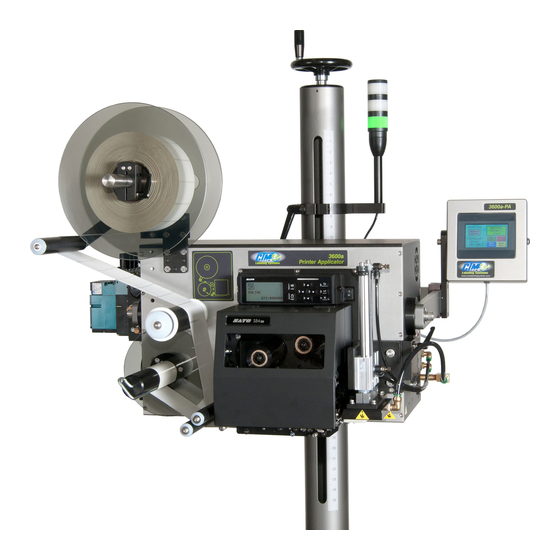
User Manuals: CTM 3600-PA Label Printer Applicator
Manuals and User Guides for CTM 3600-PA Label Printer Applicator. We have
1
CTM 3600-PA Label Printer Applicator manual available for free PDF download: Maintenance And Service Manual
CTM 3600-PA Maintenance And Service Manual (188 pages)
Brand:
CTM
| Category:
Label Maker
| Size: 10 MB
Table of Contents
Table of Contents
2
Table of Figures
4
Electrical Supply
6
Air Supply
6
Environment
6
Web Path Diagram
8
Machine Terms
18
Applicator Display Panel
20
Keys Overview
20
Changing Variable Fields
21
Alarm Screens
22
Rear Panel
23
Connector Descriptions
23
I/O Port Functions
24
Applicator Setup
25
Unwind Disks
25
FIGURE 1 (Unwind Assembly)
25
Air Filter Installation
26
Valve Banks View
26
Valve Bank
27
FIGURE 3 (Standard Tamp Assembly)
27
FIGURE 4 (Extended Peel Edge Assembly)
28
Swing Tamp Assembly
29
FIGURE 5 (Swing Tamp)
29
Ribbon Loading
30
Label Loading
30
FIGURE 6 (Web Path)
30
Applicator Nose Setup
31
Tamp Setup
32
Changing Tamp Modes
32
Label Static Test
33
Configuration Menus
34
Tamp Mode
34
Printer Type
34
External Print
34
Sato Printers
34
Label on Pad
35
Set-Up of Threshold Value
35
Vacuum-Off Option
35
Tamp Enabled/Disabled on Power-Up
35
Disable Tamp on Pause
36
Rewind Delay on and Delay off Timers
36
Tamp Home Option
36
Tamp Extend Option
36
Label Reissue Option
37
Label Reprint Option
37
Zebra Printers
37
Product Setup
38
Applicator Attitudes
38
Positioning the Applicator
39
Standard Product Sensor Setup
39
Optional Product Sensor Setup
40
Label Placement
40
Applicator Alarms
41
Warning Alarm Output
41
Critical Alarm Output
41
Alarm Light
41
Systems Ready Output
41
Alarms and the I/O Port
42
Adjusting the Low Label Sensor Mount
42
Maintenance
43
Dancer Arm Adjustment
44
Rewind Clutch Adjustment
45
Changing Clutch Pad
46
Belt Tension
46
Troubleshooting
47
Printer Settings
51
Sato Printers
51
Transmit/Receive Switches
52
Data Bit Selection
52
Parity Selection
52
Stop Bit Selection/Baud Rate Selection
52
Printer Set-Up Switches
53
Protocol Selection
53
Print Mode Selection
53
Sensor Type Selection/Head Check Selection
53
Hex Dump Selection
54
Receive Buffer Selection
54
Protocol Code Selection
54
Emulation Mode
54
Backfeed Selection
55
Label Sensor Selection
55
External Signal Interface Switches
56
External Print Signal Selection
56
External Signal Type Selection
56
Repeat Via External Signal
56
Printer Applicator Spare Parts List
58
Core Unit Spare Parts List
58
Non-Powered Unwind Assembly Parts List
59
Powered Unwind Assembly Parts List
59
Rewing Assembly Parts List
59
Tamp Spare Parts List
60
Swing Away Tamp Spare Parts List
61
Swing Tamp Spare Parts List
62
Dual Action Tamp (DAT) Parts List
63
Options Spare Parts List
64
Spare Parts List for Retired Assemblies
65
12" Unwind TAG Tamp CTM Assembly - In-Line Flow Diagram
66
12" Unwind TAG Tamp CTM Assembly - Perpendicular Flow Diagram
67
Core Unit Diagram
68
12" Unwind Standard Tamp CTM Assembly Diagram
69
12" Unwind Ext. Tamp CTM Assembly Diagram
70
12" Unwind Swing Tamp CTM Assembly Diagram
71
Touch and Go (TAG) Assembly, In-Line Flow Diagram
72
Touch and Go (TAG) Assembly, Perpendicular Flow Diagram
73
12" Unwind Assembly W/ Unwind Disc Modules Diagram
74
Standard Tamp Assembly Diagram
76
Extended Tamp Assembly for STD PE & Wide PE Diagram
77
Standard/2" Oversize/4" Oversize Swing Tamp Diagram
78
Standard/2" Oversize/4" Oversize Corner Wrap Diagram
79
Perpendicular Swing Tamp Diagram
80
Standard Slide Assembly for 3600-PA Applicator Diagram
81
Heavy Duty Slide Assembly for 3600-PA Applicator Diagram
82
Standard Slide Ass'y for 3600-PA Applicator W/ Quick Change Pad
83
Heavy-Duty Slide Ass'y for 3600-PA Applicator W/ Quick Change Pad
84
Standard Tamp Slide Diagram
85
Heavy-Duty Tamp Slide Diagram
86
Swing-Away Tamp Slide - LH Diagram
87
Swing-Away Tamp Slide - RH Diagram
88
Rewind Clutch Assembly Diagram
89
Rewind Bearing Block with Shaft Diagram
90
24 VDC Power Supply Assembly Detail Diagram
91
Electric Shelf Assembly Diagram
92
3 Station Valve Bank Assembly (Tamp) Diagram
93
Tamp: Valve Bank Assembly with Vacuum off Option Diagram
94
End of Web Sensor Wigh Mounting Bracket Diagram
95
Rewing Motor and Pulley Assembly Diagram
96
Standard Rewind Spindle Diagram
97
Rewing Motor Assembly Diagram
98
RH/LH Unwind Block Assembly Diagram
99
Housing Schematic W/ Oriental Motor Diagram
100
24 VDC Power Supply/Wiring Diagram
101
Double Light Stack Wiring Diagram
102
Triple Light Stack Wiring Diagram
103
Single Light Stack Wiring Diagram for Ready, Warning, Critical Signals
104
Tamp Return Sensor (Photo-Electric) Wiring Diagram
105
Tamp Return Sensor (Mechanical) Wiring Diagram
106
Tamp/Swing Home Sensor (Cylinder Mount) Diagram
107
Low Label Sensor and Mounting Bracket Diagram
108
Parallel to Ethernet Adapter Assy Diagram
109
External Ethernet Assembly Diagram
110
Alarm Light Stack Enclosure Assembly Diagram
111
Valve Bank Diagram
113
Tamp: Valve Bank Assembly W/ Vacuum off Option Diagram
114
Housing Schematic Prior to Oriental Motor
115
Key Descriptions
117
DAT Introduction
118
Dual Action Setup
129
Applicator Nose Installation
130
General Setup Procedures
131
Dual Action Tamp Setup
132
Dual Action Tamp Shock Absorbers and Flow Controls
133
Extend and Retract Times
133
Tamp Action Setup
135
Apply Action
135
Tamp Action
136
Swing or Tamp
136
Lead or Trail Apply
136
Encoder Option
136
Pulse Length
137
Encoder Rate
137
Input 6 Configuration
137
Tamp Is Disabled/Enabled on Power up
137
Rewind Delay on and Delay off Menus
138
Disable Label Rate Alarm
138
Double Product Detect Signal
138
Remote Alarm Reset
138
Misc. Notes
139
Product Detect Sensor Position
142
Perpendicular DAT CTM Assembly Diagram
143
In-Line DAT Assembly Diagram
144
Perpenducular DAT Shelf Assembly and Module Levels Diagram
145
Inline DAT Shelf Assembly and Module Levels Diagram
146
Swing Arm Pivot Assembly Diagram
147
DAT 4-Station Valve Bank Assembly Diagram
148
DAT Applicator Housing (Serial/Parallel/Ethernet) Diagram
149
Optional Shock Assembly for 3600-PA In-Line DAT Diagram
150
Optional Shock Assembly for 360/3600 Per. DAT & 360 In-Line DAT
151
DAT Housing Schematic Diagram
152
Vacuum Switch Assembly for 3600 & 3600-DAT Diagram
153
Vacuum Switch Additional Piping for 3600 & 3600-DAT Diagram
154
4-Station Valve Bank Assembly Diagram
155
Maintenance and Service
156
Corner Wrap Printer - Introduction
158
Corner Wrap Setup
159
Standard Corner Wrap Apply Sequence
159
Vacuum off Apply Sequence
159
Apply Sequence
160
12" Unwind Swing Tamp for Hi/Lo Pressure Corner Wrap Diagram
164
Module for the Hi/Lo Pressure Corner Wrap Diagram
165
LH Hi/Lo Corner Wrap Valve Bank Assy for Standard Apply Diagram
166
RH Hi/Lo Corner Wrap Valve Bank Assy for Standard Apply Diagram
167
LH Swing Tamp: Hi/Lo Pressure Corner Wrap for Vacuum off Option
168
RH Swing Tamp: Hi/Lo Pressure Corner Wrap for Vacuum off Option
169
Housing Schematic W/ Oriental Motor for Std. and Hi/Lo Pressure
170
Powered Unwind Printer
172
Web Path and Label Installation
174
Powered Unwind Setup
175
Setting the Unwind up
175
Setting the Rewind up
176
Powered Unwind W/ Standard Tamp Diagram
177
Housing Assembly Diagram
178
Powered Unwind Module Diagram
179
Powered Unwind Assembly Diagram
180
Unwind Dancer Assembly Diagram
181
Serial/Parallel/Ethernet Connector Plate Assembly Diagram
182
Electrical Shelf Arrangement Diagram
183
Rewind Dancer Arm Assembly Diagram
184
Inside Unwind Disk Assembly Diagram
185
Powered Unwind Schematic
186
Powered Unwind: Eow/Unwind/Rewind Sensor Wiring Diagram
187
Advertisement
Advertisement
Related Products
CTM 360a series
CTM 360 Series
CTM 360y
CTM CHARISMA 3.0 2024
CTM Categories
Bicycle
Scooter
Wheelchair
Label Maker
Bicycle Accessories
More CTM Manuals
Login
Sign In
OR
Sign in with Facebook
Sign in with Google
Upload manual
Upload from disk
Upload from URL