Table of Contents
Advertisement
Advertisement
Table of Contents

Related Manuals for Delta DVW-W02W2-E2

Summary of Contents for Delta DVW-W02W2-E2
- Page 1 2016-11-25...
- Page 2 DVW Series Industrial IEEE 802.11 a/b/g/n Wireless AP/WDS/Client/Gateway User Manual Contents Chapter 1 Introduction Feature ..................1-4 1.1.1 High Performance Network Technology ........1-4 1.1.2 Industrial Grade Reliability ............1-4 1.1.3 Robust Design ................. 1-4 1.1.4 Front Panel Ports and LEDs ............1-5 1.1.5 Below Panel ................
- Page 3 3.3.1.4 TCP Client Mode ..............3-18 3.3.1.5 Virtual COM Mode .............. 3-23 3.3.1.6 UDP Mode ................. 3-26 3.3.1.7 Pair Connection Mode ............3-30 3.3.2 Port Configuration ..............3-32 3.3.3 MODBUS Cache Table ............3-33 WLAN Manager ................3-36 3.4.1 Operation Mode ..............3-36 3.4.1.1 AP Mode ................
- Page 4 3.6.3 Relay Alarm ................3-65 3.6.3.1 Relay Event Types ............. 3-65 3.6.4 SNMP Trap ................3-66 3.6.4.1 Trap Event Types ............... 3-66 3.6.4.2 SNMP Trap Receiver Settings ..........3-66 Monitoring Settings ..............3-67 3.7.1 Email Alarm Table ..............3-67 3.7.2 Relay Alarm Table ..............
- Page 5 4.1.2.2 Configuration Web Page ............4-8 4.1.3 Tools ..................4-9 4.1.3.1 Parameter Import ..............4-9 4.1.3.2 Parameter Export .............. 4-10 4.1.3.3 Device Reboot ..............4-10 4.1.3.4 Update Firmware ............... 4-11 4.1.4 Help ..................4-11 Appendix A Private MIB Group Private MIB Group ................A-2 Appendix B MODBUS TCP Map MODBUS TCP Map ................
- Page 6 Chapter 1 Introduction Table of Contents Feature....................... 1-4 1.1.1 High Performance Network Technology ............1-4 1.1.2 Industrial Grade Reliability ............... 1-4 1.1.3 Robust Design ..................1-4 1.1.4 Front Panel Ports and LEDs ..............1-5 1.1.5 Buttom Panel ..................1-6 Antenna Installation .................. 1-7 1.2.1 Package Checklist ...................
-
Page 7: About This Manual
The user manual is suitable for DVW-W02W2-E2 and DVW-W02W2-E2-CN. Owing to the limitation of the radio frequency policy, if you need to use the Delta DVW series products in China areas, please refer to the model name DVW-W02W2-E2-CN on the Delta website, or contact our branch offices or distributors. -
Page 8: Ce Declaration Of Conformity
Ch a pt er 1 Pr o d uc t I ntr od uc ti o n CE Declaration of Conformity The DVW series switches are CE certificated products, they could use in any kind of the environments under CE environment specification. -
Page 9: Feature
DVW Ser i es I n dus tr ia l IE E E 8 02 .11 a/ b/ g/ n W ir el es s A P/W DS/C l ie nt /G a t e wa y Us er Ma n ua l Feature Thank you for purchasing the DVW Industrial Wireless AP/WDS/Client/Gateway. -
Page 10: Front Panel Ports And Leds
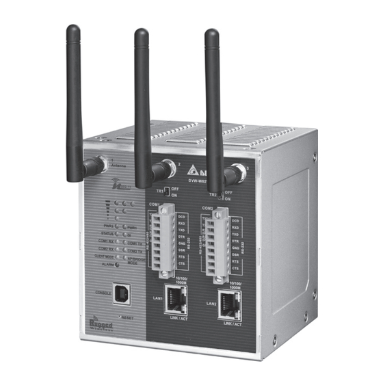
Ch a pt er 1 Pr o d uc t I ntr od uc ti o n 1.1.4 Front Panel Ports and LEDs Antenna Terminal Resistor PWR LED Status LED Serial Ports DI LED COM TX/RX LED RJ45 Ports USB Console Port Reset Button 1 - 5... -
Page 11: Buttom Panel
DVW Ser i es I n dus tr ia l IE E E 8 02 .11 a/ b/ g/ n W ir el es s A P/W DS/C l ie nt /G a t e wa y Us er Ma n ua l 1.1.5 Buttom Panel Grounding Screw... -
Page 12: Antenna Installation
Please connect 3 antennas to the DVW device. You can adjust the direction or angle of the antennas if the wireless signal is unstable. 1.2.1 Package Checklist One Delta DVW Wireless AP/WDS/Client Gateway Omni-directional Antenna x3 Wall mounting Plate x1 ... - Page 13 Chapter 2 User Interface Introduction Table of Contents USB Console Configuration ............2-2 Telnet Console Configuration ............2-7 Web Browser Configuration ............2-8...
-
Page 14: Usb Console Configuration
You can use terminal software to connect to Delta DVW devices. Before you use CLI interface, please plug USB cable on USB port with baud rate 115200. The inactivity timeout value on a serial port connection can be... - Page 15 Chapter 2 User Interface Introduction Below is an example to show you how to set the device name. Open terminal software, and select an appropriate COM port for Console Connection, 115200 for Baud Rate, 8 for Data Bits, None for Parity, and 1 for Stop Bits, None for Flow Control. Type clash and then press Enter.
- Page 16 DVW Series Industrial IEEE 802.11 a/b/g/n Wireless AP/WDS/Client/Gateway User Manual Type system_info_setting and then press Enter. PS. You can make full by use TAB to complete the command that you want to type. Type set_device_name and the new device name, such as “test”, and then press Enter.
- Page 17 Chapter 2 User Interface Introduction The device name had changed to “test”, you can use “get_device_name” to see it. Type exit to exit this CLI session. 2 - 5...
- Page 18 DVW Series Industrial IEEE 802.11 a/b/g/n Wireless AP/WDS/Client/Gateway User Manual Sometimes if you don’t know how to use the command (such as what does this command mean, or how to set the parameter in right format, etc), you can type “?” to see the help information. For example, if you want to set the local time to 2014/02/27 10:11:30, you may know type time_setting and then type set_local_time, but the next? How should I input the time? You can type ? to see the help information.
-
Page 19: Telnet Console Configuration
Chapter 2 User Interface Introduction Telnet Console Configuration Delta DVW device supports telnet server function; it can be globally enabled or disabled. The user can use all CLI command over a telnet session. Open a Command Prompt and input “telnet 192.168.1.5” to login to Delta DVW device. -
Page 20: Web Browser Configuration
DVW Series Industrial IEEE 802.11 a/b/g/n Wireless AP/WDS/Client/Gateway User Manual Web Browser Configuration Delta DVW devices support a friendly web interface for normal user to configure the switch. You can monitor the port status of Delta DVW device, and configure the settings of each function via web. - Page 21 Chapter 3 Featured Functions Table of Contents System ..................3-4 3.1.1 System Information ..............3-4 3.1.2 System CPU Status ..............3-4 Basic Configuration ..............3-5 3.2.1 System Information Configuration ..........3-5 3.2.2 Network Configuration..............3-5 3.2.3 Time Configuration ..............3-8 3.2.3.1 Local Time Configuration ............
- Page 22 DVW Series Industrial IEEE 802.11 a/b/g/n Wireless AP/WDS/Client/Gateway User Manual 3.4.2.2 Basic Wireless Configuration – Client Mode ........ 3-41 3.4.2.3 Basic Wireless Configuration – Repeater Mode ......3-42 3.4.2.4 Basic Wireless Configuration – Master Mode ......3-44 3.4.2.5 Basic Wireless Configuration – Slave Mode ........ 3-46 3.4.2.6 Basic Wireless Configuration –...
- Page 23 Chapter 3 Featured Function 3.7.8 Serial Port State ............... 3-70 3.7.9 Serial Port Statistics ..............3-70 3.7.10 Serial Port Error ............... 3-70 3.7.11 Serial Port Log ................. 3-70 Management Access .............. 3-71 3.8.1 SSH Configuration ..............3-71 3.8.2 Telnet Configuration..............3-71 Maintenance ................
-
Page 24: System Information
DVW Series Industrial IEEE 802.11 a/b/g/n Wireless AP/WDS/Client/Gateway User Manual 3.1 System This group includes System Information and System CPU Status. 3.1.1 System Information This page summarizes the current status of system. The information is categorized into several groups: System Info, Device Info and 802.11 Info. -
Page 25: Basic Configuration
3.2.1 System Information Configuration The System Information Configuration includes Device name, Device location, Device description and Device contact information. By default, the Device name is DVW-W02W2-E2 and the Device description is Series Industrial IEEE 802.11a/b/g/n wireless AP/bridge/client. Item... - Page 26 DVW Series Industrial IEEE 802.11 a/b/g/n Wireless AP/WDS/Client/Gateway User Manual DHCP-Client: If there is a DHCP server on the network, and the DVW series is in DHCP-client mode, the DVW series can receive requests from the DHCP server. If there is no DHCP server presented on the network, the IP address will be configured to 192.168.1.5 and the IP subnet mask to 255.255.255.0.
- Page 27 Chapter 3 Featured Function The DHCP pool will start from 192.168.1.1 to 192.168.1.254. Description Factory Default IP Configuration Specify the IP status of the network interface. DHCP-Client: The DVW series receives its IP configuration settings from the DHCP server. ...
-
Page 28: Time Configuration
DVW Series Industrial IEEE 802.11 a/b/g/n Wireless AP/WDS/Client/Gateway User Manual Description Factory Default 3.2.3 Time Configuration 3.2.3.1 Local Time Configuration The local time can be set manually or get from NTP server dynamically. In order to get local time dynamically, user should configure the time zone and time servers correctly. -
Page 29: Ntp Server Configuration
NTP time server or no internet connection or when the device has not been operated for a long time, or for the initial setup . 3.2.3.2 NTP Server Configuration When Delta DVW series get valid local time, DVW series can enable NTP Server to supply the time service for LAN clients. Description... -
Page 30: Serial Configuration
DVW Series Industrial IEEE 802.11 a/b/g/n Wireless AP/WDS/Client/Gateway User Manual Description Factory Default Disable: The NTP server function is disabled. NTP server 1/2 Specify the IP address or domain name of NTP server of DVW series. The www.deltawifi.com second NTP server will be used if the first NTP server can’t be connected. www.deltawifi.net 3.3 Serial Configuration DVW provides 2 kinds of serial function, MODBUS Gateway function and Serial Server function. - Page 31 Chapter 3 Featured Function can specify the range of map ID on each serial port, and then DVW series will forward the message to the serial device according to the map ID table. Description Factory Default Operation Mode Display the operation mode of serial port. MODBUS ASCII Slave Station ID...
-
Page 32: Modbus Ascii/Rtu Master
DVW Series Industrial IEEE 802.11 a/b/g/n Wireless AP/WDS/Client/Gateway User Manual Description Factory Default Port 1: 246 Specify the station ID of the device. Port 2: 247 TCP Alive Time Specify how long the DVW series keeps the TCP session when there is no TCP activity in specified time. - Page 33 Chapter 3 Featured Function Description Factory Default Operation Mode Display the operation mode of serial port. MODBUS ASCII Master Station ID Port 1: 246 Specify the station ID of the device. Port 2: 247 TCP Alive Time Specify how long the DVW series keeps the TCP session when there is no TCP activity in specified time.
- Page 34 DVW Series Industrial IEEE 802.11 a/b/g/n Wireless AP/WDS/Client/Gateway User Manual Description Factory Default Retry Specify the retry time when the time of Response Timeout reached. MODBUS Exception Specify whether the device send an exception code back to the client when the Enabled response timeout is reached.
-
Page 35: Tcp Server Mode
Chapter 3 Featured Function 3.3.1.3 TCP Server Mode In TCP Server Mode, DVW series works as a passive role. DVW series waits the connected requirement from the host computer or device. The host must send a request message to DVW series for establish the connection first. - Page 36 DVW Series Industrial IEEE 802.11 a/b/g/n Wireless AP/WDS/Client/Gateway User Manual Description Factory Default Fixed Length Specify whether sends the packet with fixed length. When the receiving data length matches with the configured value, the data will be sent. Notice: Disabled/1024 Before you enter the value of fixed length, please remember to tick the Enable option, otherwise the Fixed Length function doesn’t work.
- Page 37 Chapter 3 Featured Function Description Factory Default Prefix Char (Hex.) Enter the Prefix Char for comparison process. FF, FF Prefix Process Specify the comparison process for the Prefix Length and Prefix Char. Include Prefix Char: The data will transmit all the Prefix Char which user entered in Prefix Char (Hex.).
-
Page 38: Tcp Client Mode
DVW Series Industrial IEEE 802.11 a/b/g/n Wireless AP/WDS/Client/Gateway User Manual Description Factory Default Aging Time Specify the time for DVW series to force pack the received serial data into the same data frame. Disabled/ Notice: 1000 (ms) Before you configure the settings of Aging Time, please remember to tick the Enable option, otherwise the Aging Time doesn’t be applied. - Page 39 Chapter 3 Featured Function Description Factory Default Operation Mode Display the operation mode of serial port. TCP Client Mode Alive Check Time Specify how long the DVW series sends a packet for checking the connection still alive. Disconnect Time Specify how long the DVW series keeps the TCP session when there is no TCP activity in specified time.
- Page 40 DVW Series Industrial IEEE 802.11 a/b/g/n Wireless AP/WDS/Client/Gateway User Manual Destination IP Table Description Factory Default Enable Specify whether the destination IP information is enabled. Unticked Local Port Specify the local listen port of DVW series for the specified destination device 8000-8007 which uses to establish the connection, ranging from 1024 to 65535.
- Page 41 Chapter 3 Featured Function Data Packing Description Factory Default Fixed Length Specify whether sends the packet with fixed length. When the receiving data length matches with the configured value, the data will be sent. Disabled/ Notice: 1024 Before you enter the value of fixed length, please remember to tick the Enable option, otherwise the Fixed Length function doesn’t work.
- Page 42 DVW Series Industrial IEEE 802.11 a/b/g/n Wireless AP/WDS/Client/Gateway User Manual Description Factory Default Suffix Specify the Suffix Length and Suffix Process of data. Notice: Disabled Before you configure the settings of Suffix Length, Suffix Char and Suffix Process, please remember to tick the Enable option, otherwise the Suffix function doesn’t work.
-
Page 43: Virtual Com Mode
Chapter 3 Featured Function 3.3.1.5 Virtual COM Mode In Virtual COM mode, DVW series can establish a network connection between the host computer and serial device. So the DVW series maps the IP address with port number to the serial port on itself. When the application on host computer doesn’t provide serial interface to connect with serial device, then Virtual COM mode can solve this problem and establish a Virtual COM connection on Ethernet interface. - Page 44 DVW Series Industrial IEEE 802.11 a/b/g/n Wireless AP/WDS/Client/Gateway User Manual Data Packing Description Factory Default Fixed Length Specify whether sends the packet with fixed length. When the receiving data length matches with the configured value, the data will be sent. Disabled/ Notice: 1024...
- Page 45 Chapter 3 Featured Function Description Factory Default Prefix Length Specify the Prefix Length for comparison process. After specify the Prefix Length, please enter the Prefix Char for process. Prefix Char (Hex.) Enter the Prefix Char for comparison process. FF, FF Prefix Process Specify the comparison process for the Prefix Length and Prefix Char.
-
Page 46: Udp Mode
DVW Series Industrial IEEE 802.11 a/b/g/n Wireless AP/WDS/Client/Gateway User Manual Description Factory Default Only Suffix Char 1: The data will transmit only Suffix Char 1 which user entered in Suffix Char (Hex.). Not Include: After the comparison process is complete, the data will be transmitted without Suffix Char which the user entered in Suffix Char (Hex.). - Page 47 Chapter 3 Featured Function Forward Table Description Factory Default Enable Specify whether the forward information is enabled. Unticked Local Port Specify the local listen port of DVW series for the device which uses to 8000-8003 establish the connection. Begin IP Address Specify the beginning of destination IP address.
- Page 48 DVW Series Industrial IEEE 802.11 a/b/g/n Wireless AP/WDS/Client/Gateway User Manual Data Packing Description Factory Default Fixed Length Specify whether sends the packet with fixed length. When the receiving data length matches with the configured value, the data will be sent. Disabled/ Notice: 1024...
- Page 49 Chapter 3 Featured Function Description Factory Default Suffix Specify the Suffix Length and Suffix Process of data. Notice: Disabled Before you configure the settings of Suffix Length, Suffix Char and Suffix Process, please remember to tick the Enable option, otherwise the Suffix function doesn’t work. Suffix Length Specify the Suffix Length for comparison process.
-
Page 50: Pair Connection Mode
DVW Series Industrial IEEE 802.11 a/b/g/n Wireless AP/WDS/Client/Gateway User Manual 3.3.1.7 Pair Connection Mode Pair Connection Master and Slave modes connect two DVW series over a network. The serial device can connect to a DVW series, and two DVW can use wired Ethernet cable or wireless way to connect each other. Then two serial devices can overcome the distance limitation of serial interface. - Page 51 Chapter 3 Featured Function Pair Connection Slave Mode Description Factory Default Operation Mode Display the operation mode of serial port. Pair Connection - Slave Alive Check Time Specify how long the DVW series keeps the connection. If the time is “0”, then the connection will remain open.
-
Page 52: Port Configuration
DVW Series Industrial IEEE 802.11 a/b/g/n Wireless AP/WDS/Client/Gateway User Manual 3.3.2 Port Configuration You can view the current communication settings for each serial port in this page. If you need to configure the settings, Parameter Value Interface RS232, RS485, RS422 Data bit 7, 8 Parity bit... -
Page 53: Modbus Cache Table
Chapter 3 Featured Function 3.3.3 MODBUS Cache Table The transmit speed of Ethernet interface is faster than serial interface, so the device on Ethernet side usually need to spend much time to wait the data from serial side after they send the request message to the device on serial side. - Page 54 DVW Series Industrial IEEE 802.11 a/b/g/n Wireless AP/WDS/Client/Gateway User Manual Description Factory Default Enable Specify whether the MODBUS Cache function is enabled. Unticked Cycle time Specify the time of sending request message with serial devices. Available size Display the remaining size for the data can be monitored. 1MB size can include 1048576 (fixed) 100,000 data.
- Page 55 Chapter 3 Featured Function Word Device Item Description Station Address The station ID of the device. MODBUS (Hex.) The MODBUS address in hexadecimal. MODBUS (Dec.) The MODBUS address in decimal. Present Value The present value of the MODBUS address. Format The format of the value as Hex, Dec or Bin.
-
Page 56: Operation Mode
The device should support AP mode, Client mode, Repeater mode and WDS (Master/Slave) mode. 3.4.1 Operation Mode Delta DVW series provides 5 operation modes for you to configure in different network environment. Before you establish your wireless network, you must specify an operation mode on DVW series. -
Page 57: Ap Mode
Chapter 3 Featured Function 3.4.1.1 AP Mode When DVW series configures as AP (Access Point) mode, it can provide the connectivity for wireless client. Please refer to section 3.4.2.1 Basic Wireless Configuration – AP Mode for more information. 3.4.1.2 Client Mode When DVW series configures as Client mode, it can provides LAN-to-WLAN connection type. -
Page 58: Wds Master And Slave Mode
DVW Series Industrial IEEE 802.11 a/b/g/n Wireless AP/WDS/Client/Gateway User Manual 3.4.1.4 WDS Master and Slave Mode When the DVW series configures as WDS Master mode, it will be enabled as a Base Station. User can add the MAC address of the repeaters. Up to 4 repeaters can be added. Please refer to section 3.4.2.4 Basic Wireless Configuration –... -
Page 59: Wlan
Chapter 3 Featured Function 3.4.2 WLAN There are different wireless configurations for various operation modes, including AP mode, Client mode, Repeater mode, WDS Master mode, and WDS slave mode. 3.4.2.1 Basic Wireless Configuration – AP Mode After you specify the Operation Mode, please add a SSID in Basic Wireless Configuration page. And click Edit button to configure the wireless settings. - Page 60 DVW Series Industrial IEEE 802.11 a/b/g/n Wireless AP/WDS/Client/Gateway User Manual Description Factory Default Operation Mode Display the current operation mode. AP mode RF Type 2.4GHz B: only support IEEE 802.11b mode G: only support IEEE 802.11g mode B/G Mixed: support IEEE 802.11b/g mixed mode ...
-
Page 61: Basic Wireless Configuration – Client Mode
Chapter 3 Featured Function Description Factory Default For the rest of the above mentioned countries: 36, 40, 44, 48 SSID Specify the name of wireless device. It is not case sensitive. You can input 1 to DELTA_11NG 32 characters for SSID and space is also allowed. SSID broadcast Specify whether the SSID broadcast is enabled. -
Page 62: Basic Wireless Configuration – Repeater Mode
DVW series. Otherwise, DVW series may not be able to connect to the wireless device. While setting the device to the client mode, it is suggested to use Delta DVW series for both AP end and the client end to minimize compatibility issues and ensure best performance. - Page 63 The bandwidth will be decreased by 50% whenever a repeater end is created. While setting the device to the client mode, it is suggested to use Delta DVW series for AP end, repeater end and the client end to minimize compatibility issues and ensure best performance.
-
Page 64: Basic Wireless Configuration – Master Mode
DVW Series Industrial IEEE 802.11 a/b/g/n Wireless AP/WDS/Client/Gateway User Manual Description Factory Default Select the specific security (not the same as the security mode of the AP end); selections are: None, WEP, WPA-PSK[TKIP], WPA2-PSK[AES], and WPA-PSK[TKIP]+WPA2-PSK[AES 3.4.2.4 Basic Wireless Configuration – Master Mode If you configure the Operation Mode to Master Mode, select the “Enable Wireless Repeater Function”... - Page 65 Chapter 3 Featured Function Description Factory Default Channel 2.4GHz Canada, Mexico, Taiwan, the United States: 1-11 The rest of the above-mentioned countries: 1~13 5GHz Asia, Australia, Canada, India, Israel, Malaysia, Mexico, Singapore, South America, the United States: ...
-
Page 66: Basic Wireless Configuration – Slave Mode
DVW Series Industrial IEEE 802.11 a/b/g/n Wireless AP/WDS/Client/Gateway User Manual Description Factory Default Wireless MAC of this device Display the MAC address of the DVW series Repeater MAC Address 1~4 Up to 4 repeater MAC addresses of the devices in the slave mode can be set. None 00:1B:2F:0D:AA:B0 或... - Page 67 Chapter 3 Featured Function Description Factory Default N Only (2.4GHz): only support IEEE 802.11n mode 5GHz A : only support IEEE 802.11a mode A/N Mixed: IEEE 802.11a/n mixed mode N Only (5GHz): only support IEEE 802.11n mode Channel 2.4GHz ...
-
Page 68: Basic Wireless Configuration – Security Mode
DVW Series Industrial IEEE 802.11 a/b/g/n Wireless AP/WDS/Client/Gateway User Manual Description Factory Default Wireless MAC of this device Display the MAC address of the DVW series MAC address of the DVW series Repeater IP address Input the repeater IP address (different from the Master mode’s IP address) 192.168.1._ Base Station MAC Address Enter the MAC address of base station. - Page 69 Chapter 3 Featured Function Description Factory Default Authentication Type Automatic: Specify the authentication type as Automatic, so the wireless client can use no matter “open system” or “shared key” to pass the Automatic authentication. Shared key: Specify the authentication type as Shared key. Encryption Strength ...
- Page 70 DVW Series Industrial IEEE 802.11 a/b/g/n Wireless AP/WDS/Client/Gateway User Manual Description Factory Default WPA2-PSK. Broadcast packets use TKIP. For unicast (point-to-point) transmissions, WPA-PSK clients use TKIP, and WPA2-PSK clients use AES. Passphrase The passphrase requires 8 to 63 ASCII characters or 64 hex digits. None Notice: The security mode WPA-PSK (TKIP) does not support 802.11n.
-
Page 71: Advanced Wireless Configuration
Chapter 3 Featured Function Description Factory Default WPA Mode WPA [TKIP]: TKIP encryption method is enabled. WPA2 [AES]: AES encryption method is enabled. WPA [TKIP] + WPA2 WPA [TKIP]+WPA2 [AES]: This setting supports both WPA (with TKIP) [AES] and WPA2 (AES). - Page 72 DVW Series Industrial IEEE 802.11 a/b/g/n Wireless AP/WDS/Client/Gateway User Manual Description Factory Default CTS/RTS Threshold Specify the threshold packet size of CTS (Clear to Send) and RTS (Request to 2347 Send). Fragmentation Length Specify the maximum packet size. Packets larger than the size programmed in this field will be fragmented.
-
Page 73: Vlan Configuration
Chapter 3 Featured Function 3.5 Advanced 3.5.1 VLAN Configuration Virtual LAN (VLAN) is a logically group network. DVW provide VLAN function base on SSID. Each SSID can be configured one VLAN ID. DVW can support up to 8 SSIDs. When DVW transmit or receive packets, it matches the SSID and VLAN ID. So that only members of the VLAN could receive packets from the same VLAN ID members. -
Page 74: Packet Control
DVW Series Industrial IEEE 802.11 a/b/g/n Wireless AP/WDS/Client/Gateway User Manual Description Factory Default Management VLAN ID Specify the management VLAN ID. Port LAN: Display the LAN port number. LAN: 1 WLAN: The wireless port for the specific SSID. The number of wireless port depends on how many SSIDs you created. -
Page 75: Filter Configuration
Chapter 3 Featured Function 3.5.2.1 Filter Configuration Settings of 3 filters, MAC filters, IP Protocol filters, and TCP/UDP port filters as well as the packet acceptance. Description Factory Default Enable Specify whether the filter configuration is enabled. Enable: Packet filter function is enabled. ... -
Page 76: Ip Protocol Filters
DVW Series Industrial IEEE 802.11 a/b/g/n Wireless AP/WDS/Client/Gateway User Manual Notice: Please check the Active check box for the entries which you want to specify and please remember to configure the policy in Filter Configuration page. 3.5.2.3 IP Protocol Filters The IP Protocol filter can accept or drop packets with specified IP protocol and source/destination addresses. -
Page 77: Tcp/Udp Port Filters
Chapter 3 Featured Function 3.5.2.4 TCP/UDP Port Filters The TCP/UDP port filter can accept or drop packets with specified port and protocol. The policy can be configured up to 8 entries. You can specify TCP or UDP protocol, and specify a single port or a range of port. If you want to specify a single port, you can leave blank in end port field;... -
Page 78: Snmp Configuration
SNMP is a member of the TCP/IP protocol suite. SNMP V1, V2 and V3 are supported on the Delta DVW series. When the SNMP protocol version is V1, V2c. the authentication type use a community string. When the SNMP protocol version is V3, then you need to specify the authentication type. - Page 79 Chapter 3 Featured Function Description Factory Default Enable Specify whether the SNMP agent is enabled. None Remote Management Specify whether remote user can manage DVW series by SNMP. None Read Community Input a community name for the device to be accessed with read-only Public permission.
-
Page 80: Storm Control
Input a data key for data encryption. None Device Object ID This field displays the Delta DVW series’s OID. Fixed 3.5.5 Storm Control A traffic storm occurs when incoming packets flood the LAN, which causes the decreasing of the network performance. -
Page 81: Auto Warning Settings
Industrial Ethernet devices in an industrial environment are very important. These devices usually need to work for a long time and are usually located at the end of the system. So if the Delta DVW seriess need to be maintained, it must provide some messages to the maintainer. Even when the maintainers or engineers do not stay in the control room, they still need to be informed the status of the devices. - Page 82 DVW Series Industrial IEEE 802.11 a/b/g/n Wireless AP/WDS/Client/Gateway User Manual Description Factory Default Cold Start Power off and then power on to start the system. Enabled Warm Start When the power is still on, restart the system. Enabled Authentication Failure Log in failure (wrong ID / Password) Enabled IP Changed...
-
Page 83: Syslog Server Configuration
Chapter 3 Featured Function Description Factory Default Pork link 1 / 2 (ON→OFF) or (OFF→ON) Enabled Port 1/2 DCD (ON→OFF) or (OFF→ON) DCD detected in the serial port, trigger I/O to (ON→OFF) or (OFF→ON) Enabled Port 1/2 DSR (ON→OFF) or (OFF→ON) DSR detected in the serial port, trigger I/O to (ON→OFF) or (OFF→ON) Enabled 3.6.1.2 Syslog Server Configuration... -
Page 84: E-Mail Server Configuration
DVW Series Industrial IEEE 802.11 a/b/g/n Wireless AP/WDS/Client/Gateway User Manual Notice: Please refer to section 3.6.1.1 Syslog Event Types for more information on the event types. 3.6.2.2 E-mail Server Configuration The E-mail server parameters can be configured in this page. The maximum e-mail addresses which you can specify are 4. -
Page 85: Relay Alarm
Chapter 3 Featured Function Description Factory Default Mail Server (SMTP) Set up the IP address or domain address of the syslog server (SMTP) None User Name / Password Set up the user name and the password for the syslog server None From Email Address Set up the administrator’s email address;... -
Page 86: Snmp Trap
DVW Series Industrial IEEE 802.11 a/b/g/n Wireless AP/WDS/Client/Gateway User Manual 3.6.4 SNMP Trap NMS (Network Management Station) usually manage and monitor many SNMP agents. If manager pre-configure the event, then the SNMP agents will send a message as a trap when the event has been triggered. -
Page 87: Monitoring Settings
Chapter 3 Featured Function Description Factory Default 1st/ 2nd Trap version Specify the SNMP trap version in SNMPv1 or SNMPv2. 1st/ 2nd Trap server IP/name Enter the IP address or the name of SNMP Trap server in your network. None 1st/ 2nd Trap community Input the community string for authentication. -
Page 88: System Log
DVW Series Industrial IEEE 802.11 a/b/g/n Wireless AP/WDS/Client/Gateway User Manual 3.7.3 Trap Alarm Table When SNMP trap event has been triggered, this page displays the event and status. Item Description Index The index of the event. Event The event which has been triggered. Status The status of the event. -
Page 89: Dhcp Client List
Chapter 3 Featured Function 3.7.5 Network Connection Status Network connection status page provides user to monitor the physical LAN port connection status. 3.7.6 AP Client List AP Client List displays all wireless which associates with DVW series currently. The information includes IP Address, MAC Address and Device Name. -
Page 90: Serial Port State
DVW Series Industrial IEEE 802.11 a/b/g/n Wireless AP/WDS/Client/Gateway User Manual 3.7.8 Serial Port State Serial Port State page displays the serial port information. You can modify the serial port settings in Port Configuration page. 3.7.9 Serial Port Statistics Serial Port Statistics page displays the number of serial Tx and Rx packet number and data transmission status for each serial port. -
Page 91: Management Access
Clear the contents of the sent or received data in port 1 or 2 3.8 Management Access Delta DVW series supports not only web interface to manage the device. You also can use CLI (Command Line Interface) to configure the DVW series by Secure Shell (SSH) and Telnet. -
Page 92: Session Timeout
DVW Series Industrial IEEE 802.11 a/b/g/n Wireless AP/WDS/Client/Gateway User Manual Description Factory Default Telnet Specify the status of Telnet. Disable: Telnet is disabled. Disable Enable: Telnet is enabled. 3.9 Maintenance Maintenance functions provide some tools for administrator to upgrade, backup data and diagnose the network. -
Page 93: Ping
Chapter 3 Featured Function Description Factory Default Old Password The current password None Set Password Set up a new password None Repeat New Password Input the new password again None Notice: For the system security, please do not use the default password and please set a new administrator password during the initial configuration. -
Page 94: Firmware Upgrade
The DVW regularly releases new firmware versions to enhance product performance and add more functions. It’s highly recommended to check and perform a firmware upgrade for your DVW series periodically. You can download the latest firmware file from Delta’s download center. Notice: ... -
Page 95: Reset To Default
Chapter 3 Featured Function 3.9.7 Reset to Default After you click the Erase button, the settings on DVW will revert to factory default settings. 3.9.8 Reboot The reboot function can reboot DVW via web interface. 3.9.9 Logout Logout can disconnect the HTTP session. After you finish the configuration, we recommend you logout for security reasons. - Page 96 DVW Series Industrial IEEE 802.11 a/b/g/n Wireless AP/WDS/Client/Gateway User Manual MEMO 3-76...
- Page 97 Chapter 4 IEXplorer Utility Introduction Table of Contents Starting the Configuration .............. 4-2 4.1.1 Device ..................4-3 4.1.1.1 Search ................4-4 4.1.1.2 Virtual COM ..............4-4 4.1.2 Settings..................4-5 4.1.2.1 Device Configuration ............4-6 4.1.2.2 Configuration Web Page ............. 4-8 4.1.3 Tools ..................
-
Page 98: Starting The Configuration
DVW Series Industrial IEEE 802.11 a/b/g/n Wireless AP/WDS/Client/Gateway User Manual Delta has many kinds of industrial products and network devices. If user has many Delta products, IEXplorer utility can provide you to search them via one interface. IEXplorer utility can search for IES series products, DVP series products and some Delta products which have extend communication card. -
Page 99: Device
Chapter 4 IEXplorer Utility Introduction After double-clicking the icon, you can see the IEXplorer interface as below: 4.1.1 Device There are three items in Devices: Search, Virtual COM and Exit. -
Page 100: Search
DVW Series Industrial IEEE 802.11 a/b/g/n Wireless AP/WDS/Client/Gateway User Manual 4.1.1.1 Search When utility can’t find any devices, the message box pops-up. The auto search function performs every 1 minute. If the device doesn’t exist anymore, then it will be moved from list view. -
Page 101: Settings
Chapter 4 IEXplorer Utility Introduction Note: Before you create a virtual COM port, we recommend you use tool’s scan function replace input IP address manually. 4.1.2 Settings IEXplorer utility provides two ways to configure the devices. You can configure the basic settings via Device Configuration or configure completely settings via Open Configuration Web Page. -
Page 102: Device Configuration
DVW Series Industrial IEEE 802.11 a/b/g/n Wireless AP/WDS/Client/Gateway User Manual 4.1.2.1 Device Configuration The login ID and password are the same as the web interface. - Page 103 Chapter 4 IEXplorer Utility Introduction After the authentication progresses, the basic setting interface displays as below: You can configure the device name, IP information, modify the password, and reset it to factory default setting in this interface.
-
Page 104: Configuration Web Page
DVW Series Industrial IEEE 802.11 a/b/g/n Wireless AP/WDS/Client/Gateway User Manual 4.1.2.2 Configuration Web Page If you select Open Configuration Web Page, the web interface will be display. Note: You can double-click the device in list view to open the configuration web page. If the device which you select doesn’t belong to a DVS or DVW series device, then utility will open DCISoft for you to configure the device. -
Page 105: Parameter Import
Chapter 4 IEXplorer Utility Introduction 4.1.3.1 Parameter Import After Parameter Import is selected, a window will pop up for you to select a file imported to the device. Importing a file to multi devices is supported. -
Page 106: Device Reboot
DVW Series Industrial IEEE 802.11 a/b/g/n Wireless AP/WDS/Client/Gateway User Manual 4.1.3.2 Parameter Export After Parameter Export is selected, a window will pop up for you to select the path to export the file. 4.1.3.3 Device Reboot IEXplorer supports you to reboot the device via utility. 4-10... -
Page 107: Update Firmware
Chapter 4 IEXplorer Utility Introduction 4.1.3.4 Update Firmware After you select Update Firmware, a window will pop up for you to select the firmware file. 4.1.4 Help After the About item in Help is selected, an information message window of IEXplorer will pop up. 4-11... - Page 108 DVW Series Industrial IEEE 802.11 a/b/g/n Wireless AP/WDS/Client/Gateway User Manual 4-12...
-
Page 109: A.1 Private Mib Group
Appendix A Private MIB Group Table of Contents Private MIB Group ................A-2 A - 1... -
Page 110: Tools
A.1 Private MIB Group Delta switch not only support standard MIBs, it also provide private MIBs. You can use SNMP tool to configure or monitor the switch’s configuration. The private MIBs are the same as standard MIBs, displays like a web tree. -
Page 111: B.1 Modbus Tcp Map
Appendix B MODBUS TCP Map Table of Contents MODBUS TCP Map ................B-2 B - 1... - Page 112 Word 1 Lo byte = month Ex: 20120918, PM9:00 Word 0 = 0x1215, Word 1 = 0x0C09 Vendor Name = "Delta Electronics, Inc." Word 0 Hi byte = 'D' Word 0 Lo byte = 'e' Word 1 Hi byte = 'l'...
- Page 113 Appendix B MODBUS TCP Map Address Offset Data Type Description Ex: Product Name = "DVW-W02W2-E2" Word 0 Hi byte = 'D' Word 0 Lo byte = 'V' Word 1 Hi byte = W' Word 1 Lo byte = '-' Word 2 Hi byte = 'W'...
- Page 114 DVW Series Industrial IEEE 802.11 a/b/g/n Wireless AP/WDS/Client/Gateway User Manual Address Offset Data Type Description Ethernet Port Information Port 1 to 2 Status 0x0000: Link down 0x1000 ~ 0x1001 1 word 0x0001: Link up 0xFFFF: No port Port 1 to 2 Communication Format 0x0000: 10M-Half 0x0001: 10M-Full 0x1100 ~ 0x1101...
- Page 115 Appendix B MODBUS TCP Map Address Offset Data Type Description WLAN Port Information WLAN Operation mode 0x0000: AP mode 0x0001: Client mode 0x4000 1 word 0x0002: WLAN bridge (point to point) 0x0003: Wireless distribution system (point to multipoint) 0x0004: Repeater mode WLAN Transmission mode 0x0000: Auto 0x0001: 802.11a...
- Page 116 0x0000: OFF 0x0001: ON IABU Internal Data ( 0x2B ) Device ID Code Object ID Description Vendor Name 0x00 "Delta Electronics, Inc." Product Code 0x01 "DVW-W02W2-E2" Firmware Version 0x01 Major.Minor Example: Major = 1, Minor = 2, Length = 4 0x02 Data byte 0: "31"...
Need help?
Do you have a question about the DVW-W02W2-E2 and is the answer not in the manual?
Questions and answers