Table of Contents
Advertisement
Quick Links
SK512GSD
Monochrome Line Scan Camera
512 pixels 14 µm x 14 µm, pixel frequency 30 / 15 MHz
Instruction Manual
11.2017
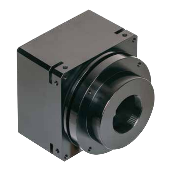
Sample Configuration
1
CCD line scan camera
SK512GSD
mounted with
2
Mounting bracket SK5105-L
3
Clamping claws SK5101
4
Video (CCTV)-objectiv
Read the manual carefully before the initial start-up. For the contents table, refer to page 3.
The right to change the described specifications is retained as the products undergo continuous cycles of improvement.
Schäfter + Kirchhoff GmbH
Kieler Str. 212, 22525 Hamburg, Germany
• © 2017-11 E
Tel: +49 40 85 39 97- 0
•
1
2
Fax: +49 40 85 39 97-79
info@SuKHamburg.de
•
•
FAST + FLEXIBLE
D
G S
5 1 2
S K
3
4
www.SuKHamburg.de
•
Advertisement
Table of Contents

Related Manuals for Schäfter+Kirchhoff SK512GSD


Summary of Contents for Schäfter+Kirchhoff SK512GSD
-
Page 1: Instruction Manual
SK512GSD Monochrome Line Scan Camera FAST + FLEXIBLE 512 pixels 14 µm x 14 µm, pixel frequency 30 / 15 MHz Instruction Manual 11.2017 5 1 2 Sample Configuration CCD line scan camera SK512GSD mounted with Mounting bracket SK5105-L Clamping claws SK5101 Video (CCTV)-objectiv Read the manual carefully before the initial start-up. -
Page 2: How To Use This Instruction Manual
According to the application, laser or high power LED light sources might be used. These can affect your eyesight temporarily or even cause permanent da- mage to the eyes or skin. Do not look directly into the light beam! Instruction manual SK512GSD 2017-11 E • © Schäfter + Kirchhoff GmbH • Hamburg... - Page 3 How to Use this Instruction Manual ................. 2 Safety Warnings ......................2 Contents ......................... 3 Introducing the SK512GSD Line Scan Camera ............4 Intended Purpose and Overview ..................... 4 System Setup at a Glance ....................... 5 Computer System Requirements .................... 6 SK512GSD Line Scan Camera - Specifications ..............
-
Page 4: Introducing The Sk512Gsd Line Scan Camera
Introducing the SK512GSD Line Scan Camera Introducing the SK512GSD Line Scan Camera Intended Purpose and Overview The SK line scan camera series is designed for a wide Features range of vision and inspection applications in both Shading Correction industrial and scientific environments. The GigE series... -
Page 5: System Setup At A Glance
Introducing the SK512GSD Line Scan Camera System Setup at a Glance red: SK512GSD scope of delivery blue: accessories for minimum system configuration black: optional accessories For accessory order details see Accessories, p. 29. Gigabit Ethernet cable Power supply cable Synchronization cable... -
Page 6: Computer System Requirements
• Network adapters that support Jumbo Frames Linux kernel 3.13 or higher • CD/DVD drive for software installation. outperform adapters with fixed packet-size frames. SK512GSD Line Scan Camera - Specifications Sensor category CCD Monochrome Sensor Sensor type IL-P3-512 Pixel number Pixel size (width x height) 14 x 14 µm... -
Page 7: Installation And Setup
Ø 4.3 incl. screws Hex socket head screw DIN 912–M3 x 12 Mounting system SK5105-2L for cameras with a tube extension > 52 mm 31.5 25 10 Ø4.3 Instruction manual SK512GSD 2017-11 E • © Schäfter + Kirchhoff GmbH • Hamburg... -
Page 8: Electrical Installation: Connections And I/O Signals
Electrical Installation: Connections and I/O Signals • For the SK512GSD line scan camera-data transfer and camera control is provded by the Gigabit Ethernet interface 3 . Use a CAT6 twisted-pair cable to connect the camera to a PC; the maximum cable length is 100 m. -
Page 9: Gige Connections And Sklinescan Software Installation
Plug in the CAT6 network cable to the camera and switch on the power supply. Then restart the system and check the driver installation with the driver installation tool The High-Performance driver is installed, further network adjustments are not required. Instruction manual SK512GSD 2017-11 E • © Schäfter + Kirchhoff GmbH • Hamburg... -
Page 10: Sklinescan Start-Up
Quit the SkLineScan startup dialog box. • Select "OK" in the SkLineScan start-up dialog. The Signal Window showing the current brightness versus the pixel number indicates the correct installation. Instruction manual SK512GSD 2017-11 E • © Schäfter + Kirchhoff GmbH • Hamburg... - Page 11 Instruction manual SK512GSD 2017-11 E • © Schäfter + Kirchhoff GmbH • Hamburg...
-
Page 12: Camera Control And Performing A Scan
, and the index order corresponds with the individual MAC addresses of the cameras. If the SK512GSD camera is identified correctly, confirm with "OK". The "Signal window" graphicaly showing the intensity signals of the sensor pixels (oscilloscope display) will open. It is responsive in real-time and the zoom function can be used to highlight an area of interest. - Page 13 Line scan in Signal Split signal window. The upper frame shows a magnified section of the lower frame. Instruction manual SK512GSD 2017-11 E • © Schäfter + Kirchhoff GmbH • Hamburg...
-
Page 14: Lens Focussing
• Dark-bright transitions with steep edges • Signal peaks are blurred • Large modulation in the signal peaks • High-frequency gray values with low • High-frequency gray value variations modulation Instruction manual SK512GSD 2017-11 E • © Schäfter + Kirchhoff GmbH • Hamburg... -
Page 15: Sensor Alignment
Gain slider 1. Adjust channel 1 zero level and minimize diffe- rence between channels using Offset slider Offset and gain adjustment for more than one gain/offset channel Instruction manual SK512GSD 2017-11 E • © Schäfter + Kirchhoff GmbH • Hamburg... -
Page 16: Shading Correction
SCM of the camera. If the load process completes then the Shading Correction is active. After shading correction, the line scan signal has a homogeneous intensity at 255 (8 bit, Maximum 100%) Instruction manual SK512GSD 2017-11 E • © Schäfter + Kirchhoff GmbH • Hamburg... -
Page 17: Shading Correction
'OK' stores the integration time values and closes the 95% of the available scale. dialog. • For synchronization settings, see section Synchro- nization of the Imaging Procedure and the Object Scan Velocity, p. 18. Instruction manual SK512GSD 2017-11 E • © Schäfter + Kirchhoff GmbH • Hamburg... -
Page 18: Synchronization Of The Imaging Procedure And The Object Scan Velocity
= 14 µm 2000 mm/s · (7.17 mm / 20 mm) Object scan velocity = 2000 mm/s 14 µm = 7.17 mm = 20 mm 51.2 kHz Instruction manual SK512GSD 2017-11 E • © Schäfter + Kirchhoff GmbH • Hamburg... -
Page 19: Integration Time
Each single line scan is triggered by the falling edge of a TTL signal supplied to LINE SYNC A input. The SK512GSD line scan camera facilitates advanced synchronization control by a second trigger input LINE SYNC B. For a detailed description, see Advanced Synchronization Control, p. 22... -
Page 20: Advanced Camera Control Functions
The parameter settings are stored in the non-volatile flash memory of the camera and are available after a rapid start-up, even after a complete shut down or loss of power. Gain/Offset Control dialog: Camera Control input and output in the right section © 2017 SK512GSD Instruction Manual (11.2017) Schäfter + Kirchhoff GmbH • Hamburg... -
Page 21: Set Commands
Acknowledgement for all set commands: xxxx = 4 digits integer value as ASCII 0 = OK, 1 = not OK yyyyy = 5 digits integer value as ASCII © 2017 SK512GSD Instruction Manual (11.2017) Schäfter + Kirchhoff GmbH • Hamburg... -
Page 22: Advanced Trigger Functions And Sync Control Register Settings
D6 = LINE SYNC A xxxxxx11 internal line counter (bit 7 ... 0) D5 = LINE SYNC B D4 ... D0 = line counter (bit 12 ... 8) Instruction manual SK512GSD 2017-11 E • © Schäfter + Kirchhoff GmbH • Hamburg... -
Page 23: Example Timing Diagrams Of Advanced Synchronization Control
'1110 0xxx'b • Trigger on 4 edges of SyncA and SyncB • direction detection = on • hysteresis = 4 Sync Control Register: '1110 1xxx'b machine holdup oscillation Instruction manual SK512GSD 2017-11 E • © Schäfter + Kirchhoff GmbH • Hamburg... -
Page 24: Sensor Information
Sensor Information Sensor Information Manufacturer: DALSA Corp. Type: IL-P3-512 Data source: DALSA IL-P3-B Image Sensors, Document 03-036-00187-09 Pin Functional Description Block Diagram © 2017 SK512GSD Instruction Manual (11.2017) Schäfter + Kirchhoff GmbH • Hamburg... - Page 25 Sensor Information Typical Performance Data and Sensor Specifications © 2017 SK512GSD Instruction Manual (11.2017) Schäfter + Kirchhoff GmbH • Hamburg...
-
Page 26: Glossary
The worst value is the determining value. In a phased set-up, both are within the same range. Instruction manual SK512GSD 2017-11 E • © Schäfter + Kirchhoff GmbH • Hamburg... - Page 27 (from high→low or low→high) are transmitted, reducing data throughput. Thresholding is particularly appropriate for measuring widths or edge positions, by simply masking the required pixel addresses. Instruction manual SK512GSD 2017-11 E • © Schäfter + Kirchhoff GmbH • Hamburg...
-
Page 28: Ce-Conformity
Date of document publication: 02.11.2017 Schäfter+Kirchhoff GmbH Tel.: +49 40 853 997-0 Kieler Straße 212 Fax: +49 40 853 997-10 22525 Hamburg Email: info@SuKHamburg.de Germany Internet: www.SuKHamburg.com Instruction manual SK512GSD 2017-11 E • © Schäfter + Kirchhoff GmbH • Hamburg... -
Page 29: Accessories
Software Software SK91GigE-WIN Order Code SDK from Schäfter + Kirchhoff including the SKLineScan operating program, as well as API, C++ class library and examples. Operating systems: Windows 7 / 8.1 / 10 - x64 and x86 SK91GigE-LV VI Order Code VI-Library for LabVIEW ®...
Need help?
Do you have a question about the SK512GSD and is the answer not in the manual?
Questions and answers