
Related Manuals for Bedfont NoxBox


Summary of Contents for Bedfont NoxBox
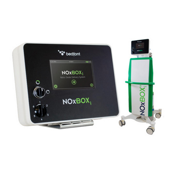
- Page 1 NOxBOX ® Technical Guide: Issue 5.0 July 2015 (Software V.17.0) saving lives, one breath at a time www.bedfont.com...
- Page 3 3.3.4 Rear Label Symbols....................... 3.3.5 Front Label Symbols ......................3.3.6 Power Supply Symbols......................3.3.7 Accessory Label Symbols ..................... 3.3.8 Manual Override Flow Sector Valve Markings ............... System Components........................... 3.4.1 NOxBOX System Features..................... NOxBOX Effect on Ventilator Circuit....................3.5.1 Oxygen Dilution ........................3.5.2 Measured Minute Volume ...................... 3.5.3 Trigger Sensitivity ........................3.5.4 Maximum NO Dose Delivery....................Installation ..............................
- Page 4 6.12.2 Using the Printed Look-up Tables ..................6.12.3 Engage Manual Override: ....................6.12.4 Manual Override Flow Selector: Approximate NO flow values..........6.13 Shutdown............................Maintenance and Repair..........................Periodic Maintenance ........................System Settings ..........................Cleaning the NOxBOX System......................Calibration............................System Replacement Parts ......................Disposable System Accessories ...................... Warranty............................. Alarms Troubleshooting..........................Alarm Priorities..........................
-
Page 5: User Responsibility
1 USER RESPONSIBILITY The NOxBOX product will perform in accordance with the description detailed in this document and accompanying guides and/or labels when assembled, operated, stored, maintained and repaired in accordance with the instructions provided. This product must be checked and calibrated in-line with the outlined service schedule recommendations. A product found to be faulty should not be used. Any parts or accessories that are broken, damaged, missing, obviously worn, distorted or contaminated should be replaced immediately. In the event of the product requiring repair or replacement, it is recommended that the customer first contacts their distributor or technical support service for the NOxBOX . -
Page 6: Safety
WARNING: Do not modify this equipment without authorisation of the manufacturer. WARNING: Read and understand this manual including any inserts/ amendments prior to using the NOxBOX . Only trained and responsible personnel should work with or around this equipment. Wear appropriate... -
Page 7: Basic Hazards
• Transportation- When transporting the NOxBOX trolley ensure the correct procedure is adhered to. Always use the handle at the front of the trolley. Ensure cylinders are securely fastened and inspect for trip hazards such as sample lines. -
Page 8: Pressure
2.1.3 Toxicity DANGER: Toxic gases can cause personnel injury or death through breathing, absorption through the skin, or swallowing. Provide adequate ventilation, appropriate personal protective equipment (PPE) and gas detection equipment. This equipment contains toxic gases. Adequate ventilation of enclosed areas serves as the chief precaution against an accumulation of toxic gases. In addition, for highly toxic gases, install automatic devices to constantly monitor gas concentrations and set off alarms if the concentrations approach a danger point. Bedfont offer suitable gas detection alarms as system accessories. Precautions against skin or eye contact with toxic gases include a thorough knowledge of the dangers, training for all personnel handling such gases, the development of procedures and equipment for handling them, and the use of special protective clothing and equipment (such as self-contained breathing apparatus (SCBA), portable gas monitors, protective garments, gloves, and face shields). -
Page 9: Poisons
Perform cleaning in accordance with applicable cleaning standards to ensure that the equipment has been safely prepared for the application for which it is to be used. Carefully inspect all cleaned parts. If any evidence of contamination is noted, clean the part again. Bedfont offer suitable instrument cleaning wipes as system accessories. -
Page 10: Electromagnetic Immunity
2.4 Electromagnetic Immunity The NOxBOX complies with the directive EN60601-1-2 electromagnetic compatibility but can be affected by cellular phones and by electromagnetic interference exceeding the levels specified in EN55011:2007 Class B. Guidance & Manufacturer’s Declaration: Electromagnetic Immunity (IEC 60601-1-2) The NOxBOX is intended for use in the electromagnetic environment specified below. The customer or the user of the NOxBOX should assure that it is used in such an environment. Immunity Test IEC 60601 Test Level Compliance Level... -
Page 11: Network Connections
2.7 Isolation from Mains WARNING: Operator should not contact the patient whilst simultaneously being in contact with the NOxBOX device. Shutdown of the system is covered in section 6.13 Shutdown. In order to isolate the system from the mains unplug the Mains Power Supply. Do not position the... -
Page 12: Equipment Description
3 EQUIPMENT DESCRIPTION The BEDFONT NOxBOX Intelligent Nitric Oxide Delivery and Monitoring System controls delivery of nitric oxide (NO) gas into the ventilator inspiratory limb of the patient breathing circuit to provide a consistent NO dose concentration in the inspired breath to the patient, as set by the user, for the purposes of Inhaled Nitric Oxide (INO) therapy. The NOxBOX system is designed to be compatible with most ventilator models, using the NOxFlow inline flow detection module to enable precise synchronized proportional NO delivery into the inspiratory limb. To ensure patient safety, the NOxBOX system provides continuous monitoring of the inhalant sample, analysing NO, oxygen (O ), and nitrogen dioxide (NO ) levels throughout treatment. It is also equipped with a full suite of alarms. The NOxBOX system has an manual override failsafe circuit for continuous application of NO.The NOxBOX system has a simple delivery calculator and a set of look-up tables to enable best flow selection. For transport and transfer conditions, the NOxBOX has a rechargeable internal battery that provides over 4 hours’ use from full charge when no mains power source is available. -
Page 13: Specification & Environment
The NOxBOX is only intended for use with, and connection to, the specified accessories and single-patient use disposables as detailed within this technical guide. 3.2 Specification & Environment NOxBOX 0-99.9 0-20.0 Measuring Range 0 – 99.9 0.6 – 80 ppm (Note the system allows setting at <= 0.5 ppm, accuracy figures below are for >= 0.6 ppm, use of a NO Delivery Range (set point) lower setting is at customer responsibility) Standby Mode Set 0ppm 200, 225, 250, 300, 400, 450, 500, 800, 900 & 1000ppm NO input concentrations NO Delivery and Measurement resolution 0.1 ppm... - Page 14 330 mm x 250 mm x 108 mm Weight: 6.2 kg Rigid polyurethane (PU) Construction: WARNING: For high concentrations of NO exceeding 80ppm, exposure should be limited to a maximum of 4 days in order to reduce the risk of sensor zero drift due to prolonged exposure. The NOxBOX protects users from the adverse effects of sensor drift by performing a daily sensor zero calibration. If a sensor has drifted outside of acceptable limits the zero calibration will fail.
-
Page 15: Definitions, Abbreviations And Icons
3.3 Definitions, Abbreviations and Icons 3.3.1 Abbreviations Nitric Oxide Nitrogen Dioxide Oxygen Parts per million 3.3.2 Definitions User setting of NO dose to deliver to patient NO Dose Elapsed Treatment Time Total patient treatment time since first NO dose delivery. Current Dose Treatment Time Time current dose setting has been administered to patient. Alarms Alarm history tab: shows alarm list from current session. Settings User settings tab: access to user-adjustable system settings 3.3.3 Icons Overview: General Navigation... -
Page 16: Rear Label Symbols
3.3.4 Rear Label Symbols Lists name and contact details of device manufacturer. Year of manufacture: date shown below this symbol indicates the year the device was made. Device serial number. Consult the Instructions for Use. Caution: specific warnings or precautions for use of this device are listed in accompanying documents. Equipment is governed by the WEEE directive. Contact your distributor for correct disposal of this device. CE Marked device. Symbol certifies that the product meets EU consumer safety, health and environmental requirements for this product type. 3.3.5 Front Label Symbols Intelligent delivery: the system is in fully adaptive delivery mode that controls the NO dose delivery to the patient to the most efficient and safe delivery profile. Manual override continuous flow: for emergency backup and manual bagging of patients. The NO flow is one of the selected flows set by the user. This flow is continuous and cannot adapt to changing conditions. Patient monitoring must be observed by operator to ensure correct dose levels are achieved. 3.3.6 Power Supply Symbols Dangerous Voltage. -
Page 17: Accessory Label Symbols
600 cc/min 3.4 System Components Each NOxBOX system has a unique serial unit identification number of the format. NI10001 This is found on the device label (Figure 0-1) attached to the rear of the device and should be quoted when contacting the manufacturer or distributor for servicing and repairs. 2014 The rear label on NOxBOX , additionally has the manufacturer contact details and year of manufacture for the device. Figure 0-1: NOxBOX Device Label... - Page 18 3.4.1 NOxBOX System Features Touch Screen Display Mode Selection Valve Manual Override Flow Control Valve NOxFlow Sensor Connector NOxFlow Dose Connector Patient Sample Inlet Water Trap Bottle Handle Quick Release Button Power Inlet Socket Charging Indicator LED Zero Inlet USB Port Power Button 15. NOxBOXi gas inlets: 4 bar max.
- Page 19 Figure 3.4.1-1: System Features NOxBOX Nitric Oxide Regulator (x2) – Connector type dependent on supplier. NOxBOX Supply Lines (x2) NOxBOX Power Supply (x1) – 4 International AC plug adaptors included.
-
Page 20: Noxbox Effect On Ventilator Circuit
3.5.1 Oxygen Dilution Adding the NO/N gas to the circuit has the effect of proportionally diluting the delivered oxygen concentration. The NOxBOX monitors the oxygen level being delivered to the patient to assist the user in monitoring this effect. Oxygen dilution is directly related to the proportion of NO gas that is added to the circuit. -
Page 21: Trigger Sensitivity
3.5.3 Trigger Sensitivity When using synchronised ventilator modes, the net change of gas volume flow caused by the NOxBOX may trip the trigger flow setting. Always check the trigger sensitivity of the ventilator after connecting the NOxBOXi to the patient circuit. 3.5.4 Maximum NO Dose Delivery The NOXBOX is capped at maximum dose capability of 80 ppm in software. Additionally, the maximum flow capability of the NOxBOX is physically limited. This will cause some dose limitations at higher ventilator flow rates. The NOxBOX is compatible with a wide range of NO supply concentrations, note that the physical flow limitation has less effect on the 1000 ppm cylinder supply compared to the 400 ppm supply. -
Page 22: Installation
4 INSTALLATION WARNING: Installation of the BEDFONT® NOxBOX system involves potentially hazardous procedures. Only trained and qualified personnel who have read and who understand the instructions in this manual shall install this equipment. Wear appropriate PPE, and, if applicable, turn off the power before performing any installation, maintenance, repair, or troubleshooting procedures. - Page 23 Align rear of monitor with trolley locking plate, and guide monitor down until button locks in position. Correctly assembled to locking plate. To release head from trolley, press quick release button and carefully lift monitor free from the locking plate.
-
Page 24: Setup Instructions
4.3 Setup Instructions To setup the NOxBOX system and prepare it for use: Ensure that the system trolley brakes are engaged during setup and in use. Insert the monitor end of the power cord into the power socket at the rear of the monitor, and push it in until the locking mechanism clicks. - Page 25 As system starts up it will run some self-test procedures to ensure correct functionability. The alarm strip should light up red and the alarm should sound. If the NOxBOX fails to alarm or show the red alarm strip, there is a system fault. Do not use this system for patient...
-
Page 26: Connecting No Gas Cylinders
Alternatively the “skip to dose” button will bypass both on-screen QSG and the system test. See Chapter 6.3 for detailed instructions for using the touch screen interface. Check that the NOxBOX NO cylinder concentration matches the value shown on the system screen. This is 1000 the value upon which delivery calculations will be based. - Page 27 WARNING: If the regulator has sustained visible damage on the valve connection surfaces do not use as it could be extremely dangerous WARNING: Ensure supply line is correctly attached to regulator output prior to opening cylinder valve. NO gas will escape at high volume which may quickly create a poisonous atmosphere.
- Page 28 Connect the line from the regulator on cylinder 1 to port 1 at the back of the monitor. Ensure the collar on the hose is drawn back prior to fitting onto the port stump. The collar should spring forward Collar sprung forward Collar drawn back and lock into place with a positive click.
- Page 29 To test that each supply line is correctly setup, perform a high-pressure leak test as follows: With the valve open, note where the pressure gauge needle is pointing. Close the cylinder valve and observe the gauge for 30 seconds. If the needle remains constant, the line is correctly set up; press the check mark. If the needle shows a drop in pressure, a leak exists; press the X. If leak detected: If the line has failed the high pressure test, then investigate the connections for any leaks:...
-
Page 30: System Test Setup
13. Once all connections have been remade, retest the pressure hold. If the line fails again the system will prompt user to connect the second line instead. Call the service engineer to make sure that any problem with the first supply line can be resolved, or the system replaced as soon as practical. Repeat the steps above for the second supply line If both lines fail after following the above procedure, this may indicate an internal leak in the system. The system must be inspected and repaired by a qualified service engineer before being used. 4.5 System Test Setup Unwrap a new NOxFlow sensor and unroll the lines. - Page 31 Identify the twin sensor line connector. Verify that both o-rings are present prior to connecting to the NOxBOX Push the sensor line connector into the socket on the side of the NOxBOX monitor, the green tube is uppermost. Connector will click in place when locked. To assist insertion, the release button located on...
- Page 32 Select the NOxKIT that matches the patient ventilator circuit size (10mm, 15mm, or 22mm). 10. From the NOxKIT, select the male-female single-sized connector and assemble one of the female luer ports by pushing it firmly home into the side port of the adaptor. Screw the male luer lock at the end of the sample line onto the ventilator adaptor.
- Page 33 WARNING: NO is extremely toxic. The system test is performed to ensure that the Test Line is correctly assembled and the NOxBOX System is functioning correctly prior to connecting to a patient. It is vital this step is done to check system function and flush out any NO build-up before connecting to a patient.
- Page 34 2, and release the line pressure using the purge needle at the back of the monitor. Then re-attach the supply lines to Port 1 and Port 2. WARNING: If the NOxBOX system is left pressurized for more than 10 minutes while not in use, repeat the system test. Connect the Line Assembly to the air supply as described in steps 11-17.
-
Page 35: Patient Circuit Setup
22M/15F outlet NO dose line NOxFlow sensor lines 5.2 System Test Circuit System Test Circuit flow meter Oxygen tubing 22F – 4.6mm connector NOxFlow™ 10M – 10F, 12M – 12F, 15M – 15F or 22M – 22F luer port connector 1m corrugated tubing (15mm or 22mm) 15M – 15M luer port or 22M – 22F luer port connector NOxBOX sample line... -
Page 36: Vent Circuit Example 1
5.3 Vent circuit Example 1 Ventilator Ventilator Inspiratory Port NOxFLOW (use 22F or 15M to vent tube adaptors) Humidifier 0.7m-1.3m Corrugated Tubing (15mm or 22mm) NOxBOX Sample Line 10M – 10F, 12M – 12F, 15M – 15F or 22M – 22F luer port connector Patient Y-piece Expiratory limb NOxBOX NOTE: To improve accuracy it is recommended to have approximately 30cm between the patient Y-Piece (8) and the sample line (6) where possible. -
Page 37: Vent Circuit Example 2
NOxBOX 5.5 Manual bagging & Manual override 5.5.1 Setup When using the NOxBOX with manual bagging or Neopuff circuit, the Manual Override mode must be selected (see section 6.12). Adaptors for the below circuits can be obtained from Bedfont Scientific to ensure compatibility. The NOxFlow delivery line should be disconnected from the NOxBOX and a manual bag specific line is connected to the NOxBOX NO outlet port (female leur connection) during manual bagging. In the case of hyper-inflating and self-inflating circuits, an O supply is typically required and can be connected to a variable flow O source such as a wall outlet with adjustable flow meter, or a cylinder with adjustable flow. Correct NO dose can be calculated and adjusted either by the changing of the manual control valve position or adjustment the flow rate of the O source (see sections 6.12.1 & 6.12.2). -
Page 38: Self-Inflating
5.5.2 Self-inflating 1. Self inflating bag 2. NOxBOX T-Piece adapter 3. 15M- 15F connector/ 22M-22F Connector 4. Oxygen connector 5.5.3 Hyper inflation Sample line 1. Hyper inflating bag 2. NO delivery line 3. 15M- 15F connector 4. Oxygen connector... -
Page 39: Neopuff Resuscitator
5.5.4 Neopuff Resucitator... -
Page 40: Operation
Additionally it could also cause irreparable damage to the system. • Devices that radiate high-intensity electromagnetic radiation could affect the correct operation of the NOxBOX system. Ensure that continuous monitoring of the system is undertaken when such devices are in operation within close proximity to the patient. - Page 41 The NO gas is a mixture of NO buffered in nitrogen. Stored in high pressure gas cylinders at a nominal fill of 150–200 bar (supplier dependent). A high-pressure regulator is attached to the valve connector of the gas cylinder. This regulator is set to a fixed outlet pressure of 4 bar when the cylinder valve is open, and a high-pressure contents gauge displays the actual fill-pressure of the cylinder. A supply line hose connects between the regulator and the NOxBOX system via quick-connect fittings. The NOxBOX system trolley can accommodate up to two NO cylinders, which are connected to the inlet ports 1 and 2 at the rear of the system respectively.
-
Page 42: Monitoring System
6.2 Monitoring System WARNING: The sample stream flow rate is set to 225 ml/min. Check the trigger sensitivity of a ventilator in synchronized mode when using the NOxBOX system to ensure that it is not being tripped by the sample stream flow. - Page 43 To navigate through these screens follow the instructions and press the next or back buttons: The system will guide you through either a single or double cylinder set-up. Select the button that corresponds to the number of supply cylinders that are to be set-up: Check the gas Supply Concentration and inspect the regulator for visible damage: Attach the Regulator and Connect the Supply Line:...
- Page 44 Open and then close the cylinder valve, check the gauge reading and then perform Pressure Hold Test: Connect the NOxFlow Sensor: Connect the Sample Line: Assemble the System Test:...
- Page 45 Users experienced in setting up the NOxBOX system may wish to skip the detailed QSG. From the Home Screen, press Skip to System Tests: The System must be correctly set-up prior to running the System Tests. The on-screen or printed QSGs are provided to help with the correct set-up. Experienced users may also skip straight...
-
Page 46: System Tests
6.4 System Tests The NOxBOX runs some system tests during start-up to ensure correct function and safe operation. The first of these tests is the Sensor Zero test. This requires no special set-up to run correctly. The system will automatically draw an atmospheric sample of gas to establish a baseline for correct sensor operation. - Page 47 Once completed successfully, the NOxBOX is ready for attachment to the patient to commence treatment.
-
Page 48: Connecting To Patient Ventilator
The system is now ready for dose entry and alarm setting procedures. See Section 5 Patient Circuit Setup for detailed guidance. 6.6 Dose Entry and Alarm Setting The NOxBOX system provides a direct-input dose control with a resolution of 0.1 ppm across the dose range from 0.6–80.0 ppm. The alarm setting for the monitored gases have suggested default values that can be fully edited for the individual case. Dose and alarm entry screens have limits on the values that can be set. - Page 49 If the dose entered is greater than 20 ppm, a warning will appear to alert you that a high clinical dose value has been entered. If a dose value of zero is entered, the system will alert user that this will stop the treatment. NOTE: All alarms will still function unless the regulator hoses are diconnected , where the system will enter stand by mode. Press next to continue The system will display a confirmation screen for the...
-
Page 50: Main Screen Display
To accept the displayed settings on this screen, press Next. To change any value, press the corresponding Edit button A final screen is displayed to commit the new dose setting to the patient. Press the check mark to commence delivery of this dose. 10. Press the cross to reject this dose and return to the summary table of values for editing. -
Page 51: Detailed Areas Of Main Screen
Press the edit button to change the edit dose delivered dose. The NO supply cylinder status shows cylinders connected to the NOxBOX Supply Supply The supply indicators warn when the Indicator Indicator cylinders are low. Check the pressure... -
Page 52: Tabbed Navigation
The treatment time clocks show: time at current Total time patient has been on dose NOxBOX treatment total treatment days:hours:mins time Time patient has been receiving days:hours:mins current dose Both clocks show the time elapsed seconds timing marker Days : Hours : Minutes The seconds timing marker is below the lower clock. -
Page 53: Change Dose And Alarms
6.7.3 Change Dose and Alarms When changing the dose, the system recalculates the alarm values to appropriate levels for the new dose setting. These values can be confirmed or edited before returning to the Main Screen. To change the dose from the main screen, press the dose edit button. -
Page 54: Standby Mode
6.7.4 Standby Mode To enter standby mode, set dose to 0ppm, remove the regulator hoses, turn off cylinders and depressurise the regulator hoses. 6.8 Screen Lock In the event of an alarm, the screen will automatically unlock. The Main Monitor Screen automatically locks itself if no interaction has occurred for 2-3 minutes. This helps prevent accidental interaction with the system settings. When the screen lock engages, it appears on the screen for 10 seconds. -
Page 55: Setting The Screen Lock Format
6.8.1 Setting the Screen Lock Format The screen lock format is set in the Service Engineer area. The system default setting is for a standard (non-coded) screen unlock. To change the screen lock format, log into Service Engineer area and select “Set screen lock format”. NOTE: Service Engineer area only available from start screen. To set screen format to a code unlock: Enter the 4-digit code and press next. This is now the code needed to unlock the screen. -
Page 56: Red Banner Alarms
Alarm notices for detected alarm conditions are displayed across the lower half of the Main Monitor screen. Pressing the buttons on the message will temporarily mute the audible alarm and dismiss the banner message. The Alarm History screen displays the last 20 alarm conditions in a scrollable list. -
Page 57: Gas Supply Alarms
The green printed arrow points towards the patient. This message may also appear where insufficient ventilator flow is present, such as with very low tidal volume applications. Increasing the bias flow may help resolve this alarm. The NOxBOX has detected a critical fault within the intelligent delivery system, and can no longer guarantee safe delivery function. Engage the Manual Override (see Section 6.12) and replace the system as soon as practical. Contact the Systems Engineer. -
Page 58: Calibration Overdue
A red banner critical alarm is triggered when the current supply cylinder is running low and there is either no other cylinder detected or the pressure detected in the other cylinder is also running low. To resolve this alarm, follow the on-screen instructions to connect a new supply cylinder to the alternate NO inlet at the rear of the monitor. -
Page 59: Other Alarms And System Alerts
6.9.4 Other Alarms and System Alerts Manual Override See section 6.12. This alarm banner will display when the manual override mode is engaged. NOxBOX System Diagnostics The system performs self-tests at set-up and during operation to ensure safe performance is maintained. In the event that a critical test fails, the... -
Page 60: Zero Calibration During Delivery
Prior to administering a high dose setting to the patient, the system will display this warning to alert the user to the dose setting selected. Stop Treatment Set To stop administering Inhaled NO Therapy, set the NOxBOX dose level to zero. The system will display warning messages so the user is aware that the stop delivery of treatment mode has been selected. - Page 61 Zero Calibration is automatically performed upon system power-on. The results of the zero calibration are displayed during the set-up procedure prior to performing the system test. During use, the system automatically reminds you once every 24 hours to perform the zero calibration procedure. This helps maintain the accuracy of the monitoring system and is a regular quick check to ensure safe performance of the system.
-
Page 62: User Settings Screen
If one or more sensors fail to perform within the expected parameters during the zero calibration, a “Zeroing Failed” message will appear, and any sensors that failed to meet the performance criteria will display a red cross next to them. Press Next for instructions. 10. If the zero calibration fails, the system will prompt to contact the service engineer and replace the system as soon as... -
Page 63: Change Volume And Brightness
Change volume and brightness Alter the volume of the screen interactive ‘beep’: volume up volume down NOTE: This does not affect the volume of any system alarm. Similarly, adjust the display brightness: brightness up brightness down Access Zero Calibration The User Settings Screen provides access to the daily zero calibration function. A reminder is displayed on the main monitor each time this is due (once every 24 hours from system start-up). The notice can be dismissed if the timing is not suitable (e.g. patient dose recently changed and still adjusting). -
Page 64: Manual Override
6.12 Manual Override The NOxBOX is equipped with a manual override delivery option to ensure continuous NO delivery even in extreme conditions such as complete power loss or a catastrophic failure of the intelligent delivery path. There are two controls associated with manual override delivery: The Mode Selection Valve The Manual Override manual flow control valve At commencement of NO delivery to the patient, it is advisable to check which flow setting on the manual override system would best suit the current treatment session and set flow selector valve to this value. 6.12.1 Determine Correct Flow Setting Access the Manual Override Calculator from the user settings screen. Use the arrow keys to adjust the ventilator minute flow to match the patient ventilator settings. The calculator table indicates the approximate expected NO dose delivery for each of the NO flow settings (50-600ml) combined with the vent/Oxygen flow. -
Page 65: Using The Printed Look-Up Tables
Override. Once flow is set, the system is ready to allow safe engagement of the Manual Override mode if required during this treatment. 6.12.2 Using the Printed Look-up Tables From the NOxBOX printed Operating Instructions, refer to the lookup tables. Select the table for the NO cylinder concentration being used Find the ventilator minute volume flow that most closely matches the patient ventilator settings. -
Page 66: Manual Override Flow Selector: Approximate No Flow Values
The system screen will display a warning message that the system is delivering through the Manual Override mode. Press the cross to dismiss this message. The “NO Dose” area of the main screen shows a constant reminder that the system is on Manual Override. To revert to intelligent delivery, position the mode selection valve to vertical. 6.12.4 Manual Override Flow Selector: Approximate NO flow values 50 cc/min Note all values shown are approximate to +/- 100 cc/min... - Page 67 Fully close each cylinder and depressurise the supply lines using the purge needle. Remove regulator from each cylinder and stow on system trolley. Remove all single patient use devices from monitor and dispose of according to local regulations. Drain water trap and dispose of drainage syringe. Recommend cleaning inside water trap with instrument wipes prior to storage.
-
Page 68: Maintenance And Repair
The system may only be serviced and repaired in accordance with the maintenance written instructions provided by Bedfont Scientific Ltd. The system should not in any way be altered without approval from the manufacturer. All replacement components must be approved for use with the system. -
Page 69: Periodic Maintenance
7.1 Periodic Maintenance Reliable and robust system performance is dependent on maintaining and servicing the NOxBOX system in accordance with the advice and training provided with this unit. Table 7-1 lists periodic maintenance tasks for the NOxBOX system. Table 7-1 Periodic Maintenance Tasks Frequency Task(s) During Use Check the NO supply cylinder pressure gauge daily. Cylinders with lower than 20 bar pressure must be replaced. Perform a zero calibration of the sensor (the system will prompt you to do this once every 24 hours). -
Page 70: Cleaning The Noxbox System
Alcohol-free instrument wipes approved for use with the NOxBOX system are available from Bedfont Scientific Ltd. 7.4 Calibration CAUTION: Temperature may affect the accuracy of the NOxBOX monitoring function. The instrument should be calibrated at the temperature at which it is expected to be used. CAUTION: In order to correctly calibrate the NOxBOX... -
Page 71: System Replacement Parts
7.5 System Replacement Parts Picture Item Order Code(s) 2 x Regulator (refer to NO gas supplier for valve connection designation) 2 x Regulator hoses FXS543 Mains Power Supply with NOXBOXI-MAIN locking jack. Model: EXM 80 5121 Input: 100-240V AC Max 1.7A Output:24V DC 1.7A Use only this power supply. Portable ambient alarms for NO and NO NO Alarm NOXAIR-NO-V Alarm NOXAIR-NO... -
Page 72: Disposable System Accessories
7.6 Disposable System Accessories The following Single Patient Use accessories are available from Bedfont Scientific for the NOxBOX System. Part Code Description Image NOXFLOW-2 Size 2 single use flow control unit NOXBOXI-SAMPLE Sample line for NOxBOX WT-DRAIN Water trap drainage syringe NOXKIT-2-22 Single use delivery and sampling kit - include 3 x 22mm male - 22mm female, 7.6 port connector, 1.8m Sample line, 1 x Elbow luer lock, NOXFLOW-2, Water trap drainage syringe FIL063 Hydrophobic Filter... - Page 73 - includes 2 x 10mm male - 10mm male, 7.6 port connector, 1 x 10mm male - 10mm female, 1 x Elbow luer lock, NOXFLOW-2, Water trap drainage syringe, 1.8m Sample line NOXKIT-2-12 Single use kit for adapting 10mm kit to 12mm circuits NOXBOX-I TEST System test kit – Includes 1,200mm corrigated tubing – sample line – oxygen line – 22f – 6mm oxygen line connector – NOXFLOW.
-
Page 74: Warranty
T-Piece – delivery hose – 22m/15f – 15m connector with luerSelf-inflating bag and additional delivery hose for illustration purposes only – NOT INCLUDED FXS555 22mm One-way valve for use with certain HFO ventilators. 7.7 Warranty For a period of twelve (12) months from the date of shipment, Bedfont Scientific Ltd warrants the NOxBOX and trolley (excluding parts listed below) to be free of defects in materials, workmanship and to conform to the description of the product contained in this Technical Guide, provided that the same is properly operated under the conditions of normal use, that regular periodic maintenance and service is performed and that replacements and repairs are made in accordance with the instructions provided. Bedfont’s sole obligation under this warranty is limited to repairing or replacing , at its choice, any item covered under this warranty when such an item is returned, intact, in it’s original packaging and prepaid* to Bedfont Scientific Ltd or the local representative. This warranty shall not apply if the product has been repaired other than by Bedfont, an authorised Bedfont representative trained in repairs or in accordance with those individuals trained by Bedfont in repairs, or altered by anyone other than Bedfont, or if the product has been subject to abuse, misuse, negligence, or accident. *Prepaid means packing, carriage, taxes, import duties and any other costs incurred in sending the product back for repair/replacement and the same for return. -
Page 75: Alarms Troubleshooting
PRIORITY COLOUR MEANING High Red 5 tone Critical problem detected. Condition poses immediate threat pattern & Red to patient health or correct functioning of the NOxBOX L.E.D. alarm monitor. Alarm condition should be diagnosed and resolved strip. immediately. Medium Amber 3 tone Problem detected. Condition may impair the functioning of the... -
Page 76: Alarm Priority- Alarms During Therapy
Alarm Priority Possible Cause Recommended Action NO Low Monitored levels of NO gas Check sample line is correctly attached to ventilator being delivered to the patient have circuit and NOxBOX water trap inlet. dropped below the alarm setting Check Sample line for blockages. boundary. NOxBOXi delivery system Check water trap (including barrel thread) for cannot mainatin correct dose setting. damage and/or leaks. Check no ventilator circuit breaks or leakages have occurred. - Page 77 Dispose of entire syringe and contents according and water ingress to the NOxBOX to local directives (e.g. sharps waste). system could damage the internal mechanisms and gas sensors.
- Page 78 Check green (mains power) L.E.D on mains power plug is lit indicating mains supply OK. If not, try a different mains power socket/supply. Disconnect power supply and reconnect, check blue (charging) L.E.D is lit indicating mains supply OK. If not, try a different mains power/supply. If possible replace NOxBOX power supply and alert service engineer. In the event that no mains power can be restored to the device, be prepared to engage the manual override mode. Cylinder NOxBOX detects that available NO gas Install a new gas cylinder supply and connect...
-
Page 79: Alarm Priority
Critical The NOxBOX has detected a critical Check the ventilator is connected and Delivery fault within the intelligent delivery supplying sufficient flow. Fault system, and can no longer guarantee If another system is not readily available and safe delivery function. patient requires therapy, engage the manual override mode, replace the system as soon as practically possible and alert the Service Engineer. Touch The NOxBOX has detected a If another system is not readily available and screen will critical fault within the intelligent patient requires therapy, engage the manual delivery system, and can no longer override mode, replace the system as soon as respond. guarantee safe delivery function. NO practically possible and alert the Service delivery to the patient may have Engineer. -
Page 80: General Troubleshooting
8.4 General Troubleshooting Issue Possible Cause Recommended action NOxBOX turns on and off Low battery power Connect NOxBOX to mains power and turn immediately. NOxBOX on NOxBOX attempts to start up but shuts down. NOxBOX won’t turn on at all. An internal fault has occurred; the If another system is not readily available... -
Page 81: Ventilator Management
System Test Fail The NOxBOX has failed the safety test Check the Oxygen source is flowing. and cannot accurately deliver and monitor Check the NOxFLOW is connected to the Nitric Oxide in intelligent mode. Oxygen source and the NOxBOXi-TEST kit. Check the correct orientation of NOxFLOW. Check the NOxFLOW is connected to the... - Page 82 Notes...
- Page 83 Notes...
- Page 84 Station Road, Harrietsham, Maidstone, Kent, ME17 1JA, England Tel: +44 (0) 1622 851122 Fax: +44 (0) 1622 854860 Email: ask@bedfont.com www.bedfont.com ISO 9001:2008 Cert No. FM 31664 Issue 5.0- July 2015. Part No: LAB638 ISO 13485:2003 © Bedfont Scientific Ltd Cert No. MD Bedfont Scientific Limited reserves the right to change or update 502905 this literature without prior notice. Registered office: England and Wales. Registered No: 1289798...
Need help?
Do you have a question about the NoxBox and is the answer not in the manual?
Questions and answers