Advertisement
Quick Links
HIP4086 3-phase BLDC Motor Drive Demonstration
Board, User's Guide
Introduction
The HIP4086DEMO1Z is a general purpose 3-phase BLDC
motor drive with a microprocessor based controller. Hall effect
shaft position sensors are used to control the switching
sequence of the three 1/2 bridge outputs. The bridge voltage
can vary between 12V and 60V and the maximum summed
bridge current is 20A (with sufficient air flow). This motor drive
can be used as a design reference for multiple applications
including e-bikes, battery powered tools, electric power
steering, wheel chairs, or any other application, where a BLDC
motor is utilized. Because this demonstration board is
primarily intended to highlight the application of the HIP4086
3-phase MOSFET driver with no specific application targeted,
the control features are limited to simple functions, such as
start/stop, reverse rotation, and braking. Open loop speed
control is implemented. More advanced control features, such
as torque control, speed regulation and regenerative braking
are not implemented because these methods require close
integration with the characteristics of the load dynamics.
Important Note
Because Hall sensor switching logic sequences for BLDC
motors are not all the same, this demo board supports most, if
not all, variations of sequence logic. Please refer to the
sequence charts in "Selecting the Correct Switching
Sequence" on page 9 to verify that your desired sequence is
implemented. If you require a different sequence for your
specific motor application or if you need help identifying the
correct switching sequence for your specific motor, please
contact Intersil prior to ordering this demo board for possible
support for a new switching sequence.
Specifications
Motor topology
Operating voltage range
Maximum bridge current
Hall sensor bias voltage
PWM switching frequency
Scope
This application note covers the design details of the
HIP4086DEMO1Z with a focus on the design implementation
of the HIP4086 driver using recommended support circuits.
Also covered, is the design method of the bipolar current
sensing feature. Presently, current sensing on this demo board
is used only for pulse-by-pulse current limiting. However, an
March 14, 2013
AN1829.0
3-phase BLDC motor with Hall
sensors
15VDC to 60VDC
20A (with sufficient air flow)
5V
20kHz
1
CAUTION: These devices are sensitive to electrostatic discharge; follow proper IC Handling Procedures.
analog signal proportional to the motor current is available on
board as a design reference.
The microcontroller firmware is also provided as a reference
but the only support offered by Intersil will be for bug
corrections and for adding more switching sequences. Please
refer to Microchip for details on the use of the PIC18F2431.
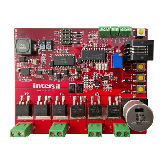
Physical Layout
The HIP4086DEMO1Z board is 102mm by 81mm. The tallest
component is a 470µF capacitor. The total height is 24mm
with standoffs or 18.5mm without standoffs. The Hall effect
shaft position sensor inputs are miniature terminal blocks and
the high current outputs are larger terminal blocks that are
rated for 20A.
Four push-buttons are used for reset, brake, reverse, and
start/stop functions. An on-board potentiometer is used to
adjust the duty cycle of the applied motor voltage or an
optional external potentiometer can be connected to a signal
terminal block located adjacent to the Hall terminal blocks.
The switching sequence selection dip switch is used for various
purposes but the most important function is to select the
desired switching sequence. Please refer to the "Setup and
Operating Instructions" on page 3 for more information.
For those customers who would like to modify the firmware of
the PIC18F2431 microcontroller, an RJ25 connector is
provided for easy connection with Microchip firmware
development tools (not provided or supported by Intersil).
FIGURE 1. HIP4086DEMO1Z INPUTS AND OUTPUTS
|
1-888-INTERSIL or 1-888-468-3774
Intersil (and design) is a trademark owned by Intersil Corporation or one of its subsidiaries.
All other trademarks mentioned are the property of their respective owners.
Application Note 1829
Author: Richard Garcia
Copyright Intersil Americas LLC 2013. All Rights Reserved
Advertisement

Related Manuals for Intersil HIP4086


Summary of Contents for Intersil HIP4086
- Page 1 CAUTION: These devices are sensitive to electrostatic discharge; follow proper IC Handling Procedures. 1-888-INTERSIL or 1-888-468-3774 Copyright Intersil Americas LLC 2013. All Rights Reserved AN1829.0 Intersil (and design) is a trademark owned by Intersil Corporation or one of its subsidiaries. All other trademarks mentioned are the property of their respective owners.
-
Page 2: Block Diagram
The microcontroller firmware is provided as a reference but the provides +5V bias for the microcontroller, dip switches, push only support offered by Intersil will be for bug corrections and for buttons, LEDs, and the current monitor/limit circuits. The adding more switching sequences. All firmware revisions for this ISL6719 is a linear regulator that provides 12V bias for the demo board can be found on the Intersil website. - Page 3 (100V, 33A). Each FET is driven by one of the six driver outputs of • FN6555 ISL6719, 100V Linear Bias Supply the HIP4086. Dead time is provided by the controller (optionally, • FN9244 ISL8560, DC/DC Power Switching Regulator dead time can be provided by the HIP4086).
- Page 4 Application Note 1829 alternative to cycling power, the reset push button can be 14. While the motor is running, press the REVERSE button. The pressed to re-read the dip switch settings. RUN LED (led0) will turn off and the REVERSE LED (led1) will turn on without blinking.
-
Page 5: Theory Of Operation
Bridge State Logic: P = PWM, L = Low, Z = off The HIP4086 has 6 driver outputs, AHO, ALO, BHO, BLO, CHO, ZLP PLZ PZL ZPL LPZ LZP ZLP PLZ PZL ZPL LPZ LZP and CLO, to control the six bridge FETs individually. - Page 6 Application Note 1829 Switching Sequence Phase Currents coils are highlighted. The inactive coils (those with no current) are white. The following motor winding diagrams illustrate how currents flow in a 3-phase BLDC motor during each switching period of the The dark gray structures are the permanent magnets that are 6 step voltage waveform.
- Page 7 The HIP4086 has a refresh pulse feature that is used to ensure that the boot caps are biased prior to driving on the high-side For example, D1 in Figure 9, functions as a negative voltage drivers.
- Page 8 Application Note 1829 Please refer to the HIP4086 datasheet for additional application The output voltage of the differential amplifier is: information. Vout [(R12||R14)) / (R17+R21)] x I x (R23||R24)+ R3 / (R3+R15) x 5V Current Monitor and Current Limit (EQ. 1) There are two current control features in the HIP4086DEMO1Z.
- Page 9 Application Note 1829 This equation assumes that the only change made to the HIP4086DEMO1Z is modifying the values of the current sensing resistors R23 and R24. R23||R24 = 4.878V - 2.5V x 1.022kΩ / (16.2kΩ x Im) (EQ. 3) For example: for I = ±5A, LIMIT R23||R24 = 4.878V - 2.5V x 1.022kΩ...
- Page 10 Application Note 1829 Dip switch positions hall sensor logic options are defined by the blue boxes: 0011 4 3 2 1 dip switch position numbers Hall sensor logic Hall sensor logic 0011 0111 0010 0110 0001 0101 B&D 0000 0100 Ametek 119056 Bridge Logic: P=PWM, L=Low, Z=off...
- Page 11 Application Note 1829 Selecting the Correct Switching Sequence Notice that the dip switch settings for these Hall sensor logic charts (Figure 15) are the same as Figure 14. This is not an error. Dip switch positions hall sensor logic options are defined by the blue boxes: 0011 4 3 2 1 dip switch position numbers...
- Page 12 Bill of Materials, Rev A TOL. PACKAGE PART NUMBER REF DES VALUE VOLTAGE POWER TYPE JEDEC TYPE MANUFACTURER DESCRIPTION 10TPE330M C8, C9 330µF CAP_7343 SANYO-POSCAP TPE SERIES LOW ESR PRODUCTS CAP 1725656 2MNT CON_TERM_MPT_2P PHOENIX- 100 Mil Micro-Pitch Terminal Block CONTACT 1725669 TB1,TB2...
- Page 13 Bill of Materials, Rev A (Continued) TOL. PACKAGE PART NUMBER REF DES VALUE VOLTAGE POWER TYPE JEDEC TYPE MANUFACTURER DESCRIPTION H1045-00104-25V10 C38, C40 0.1µF CAP_0603 GENERIC Multilayer Cap H1045-00221-50V10 220pF CAP_0603 GENERIC Multilayer Cap H1045-00224-16V10 C35-C37 0.22µF CAP_0603 GENERIC Multilayer Cap H1045-00391-50V10 390pF CAP_0603...
- Page 14 Thick Film Chip Resistor H2513-001R2-1/8W1 R2, R56, R57 1.2Ω 1/8W 1206 RES_1206 GENERIC Thick Film Chip Resistor HIP4086ABZ SOIC SOIC24_300_50 INTERSIL Three Phasre Driver 80v 0.5A IRFS4710 Q1-Q6 D2PAK D2PAK N-Channel 100V 75A HEXFET Power MOSFET ISL28246FUZ U2, U3 MSOP MSOP8_118_256...
- Page 15 HIP4086DEMO1Z Board Schematics RJ11 V_48V V_5V 22.0UH 19 18 DR125-220-R ISL8560IRZ BOOT PGND PGOOD VCC5 0.01UF 100PF 301K 390PF 0603 VPWR RJ10 V_12V ENABLE_N ENABLE AUXIN COMPB COMPA VSW_FB ISL6719ARZ FIGURE 16. BIAS SUPPLIES...
- Page 16 HIP4086DEMO1Z Board Schematics (Continued) V_5V EXTERNAL MCLR SPEED CONTROL POTENTIOMETER (OPTIONAL) IMOT MCLR PWM4 PWM5 HALL SWITCHES PWM3 PWM2 PWM1 AVDD V_5V AVSS PWM0 OSC1 HALL BIAS OSC2 V_5V PIC18F2431S0 /FLTA CONTROLLER PROGRAMING PORT V_5V MCLR 555165-1 FIGURE 17. CONTROLLER...
- Page 17 HIP4086DEMO1Z Board Schematics (Continued) V_48V FOR NO DEAD TIME DELAYS: TO DISABLE BRIDGE RJ4= 0 OHM, R5 = OPEN. DRIVER WHILE TROUBLE- SHOOTING CODE: FOR DEAD TIME DELAYS: IRFS4710 RJ4= OPEN, R5=10K...100K. RJ3 = O OHM V_12V IRFS4710 IRFS4710 PWM3 /BHI PWM2 PWM0...
-
Page 18: Pcb Layout
Application Note 1829 PCB Layout RESET BRAKE REVERSE START/STOP -BATT BATT R11B LED0 LED1 R12A LED2 R12B LED3 D12 D13 R43 R44 R45 R35 RJ10 HIP4086DEMO1ZA FIGURE 19. PCB SILKSCREEN, REV A AN1829.0 March 14, 2013... - Page 19 Application Note 1829 PCB Layout (Continued) RESET BRAKE REVERSE START/STOP -BATT BATT R11B LED0 LED1 R12A LED2 R12B LED3 D12 D13 R43 R44 R45 R35 RJ10 HIP4086DEMO1ZA FIGURE 20. SILKSCREEN WITH PADS, REV A AN1829.0 March 14, 2013...
- Page 20 Application Note 1829 PCB Layout (Continued) FIGURE 21. TOP LAYER, REV A AN1829.0 March 14, 2013...
- Page 21 Application Note 1829 PCB Layout (Continued) FIGURE 22. LAYER 2, REV A AN1829.0 March 14, 2013...
- Page 22 Application Note 1829 PCB Layout (Continued) FIGURE 23. LAYER 3, REV A AN1829.0 March 14, 2013...
- Page 23 Application Note 1829 PCB Layout (Continued) FIGURE 24. BOTTOM LAYER, REV A AN1829.0 March 14, 2013...
- Page 24 Application Note 1829 Test Mode red arrows indicate a flashing LED To validate the correct performance of the HIP4086 demo board, valid test mode led3 led2 led1 led0 startup, no flashing a built-in test procedure can be used to verify that the board is fully functional.
- Page 25 2. The end. Intersil Corporation reserves the right to make changes in circuit design, software and/or specifications at any time without notice. Accordingly, the reader is cautioned to verify that the Application Note or Technical Brief is current before proceeding.
- Page 26 Mouser Electronics Authorized Distributor Click to View Pricing, Inventory, Delivery & Lifecycle Information: Intersil HIP4086DEMO1Z...
Need help?
Do you have a question about the HIP4086 and is the answer not in the manual?
Questions and answers