Table of Contents
Advertisement
READ ALL OF THE INSTRUCTIONS THOROUGHLY BEFORE OPERATING THIS BOILER.
This manual provides information on the installation of the boiler. For proper operation and safety, it is important to
follow the instructions and adhere to the safety precautions.
A licensed professional must install the boiler according to the exact instructions of the manual.
If the information in these instructions is not followed exactly, fire or explosion
Warning
may result causing property damage, personal injury, or death.
- Do not store or use gasoline or other flammable vapors and liquids in the vicinity of this or any other
appliance.
- What to do if you smell gas
• Do not try to light any appliance.
• Do not touch any electrical switch; do not use any phone in your building.
• Immediately call your gas supplier from a neighbor's phone. Follow the gas supplier's instructions.
• If you cannot reach your gas supplier, call the fre department.
- Installation and service must be performed by a licensed professional.
The installation must conform with local codes or, in the absence of local codes, the National Fuel
Gas Code, ANSIZ223.1/NFPA 54 and/or CSA B149.1, Natural Gas and Propane Installation Code.
REVOLUTION CONDENSING
COMBI-BOILERS
Installation
Manual
Model
VRC-80 VRC-100
VRC-120 VRC-140
Keep this manual near this boiler for future reference
whenever maintance or service is required.
Advertisement
Table of Contents

Subscribe to Our Youtube Channel
Related Manuals for Vesta VRC-100


Summary of Contents for Vesta VRC-100
- Page 1 REVOLUTION CONDENSING COMBI-BOILERS Installation Manual Model VRC-80 VRC-100 VRC-120 VRC-140 Keep this manual near this boiler for future reference whenever maintance or service is required. READ ALL OF THE INSTRUCTIONS THOROUGHLY BEFORE OPERATING THIS BOILER. This manual provides information on the installation of the boiler. For proper operation and safety, it is important to follow the instructions and adhere to the safety precautions.
-
Page 2: Safety Information
Safety Information The following safety symbols are used in this manual for user's safety. Read this manual carefully and follow all instructions to avoid property damage, fire, explosion, personal injury, or death. Danger Indicates an imminently hazardous situation which, if not avoided, will result in severe injury or death. Warning Indicates a potentially hazardous situation which, if not avoided, will result in injury or death. - Page 3 Warning • Do not store combustibles, such as papers or laundry, near the boiler or venting system. Failure to do so may result in fire or explosion. • Do not store or use gasoline or other flammable liquids near this boiler. Failure to do so may result in fire or explosion.
-
Page 4: Important Note For The State Of Massachusetts
Important Note for the State of Massachusetts NOTICE BEFORE INSTALLATION This appliance must be installed by a licensed plumber or gas fitter in accordance with the Massachusetts Plumbing and Fuel Gas Code 248 CMR Sections 4.00 and 5.00. IMPORTANT: In the State of Massachusetts (248 CMR 4.00 & 5.00) For all side wall horizontally vented gas fuelled equipment installed in every dwelling, building or structure used in whole or in part for residential purposes, including those owned or operated by the Commonwealth and where the side wall exhaust vent termination is less than seven (7) feet above finished grade in the area of the venting, including but not limited to decks and porches, the following requirements shall... - Page 5 Table of Contents Safety Information ........2 Installing a Vent ........29 Vent Type ................29 Important Note for the State of Vent Pipe Materials ............33 Massachusetts ........... 4 Vent Length ...............33 Connecting the Vent Clip ..........34 General Information ........6 Vent Termination .............34 Included Items ..............
-
Page 6: General Information
General Information Included Items Optional Accessories The following items are included with the boiler. Check each of the The following optional accessories are not included with the boiler, following items before installation. but may be necessary for the installation. Check the need for any of the following optional accessories before installation. -
Page 7: Specifications
Specifications The following table shows the specifcations for the boiler. Additional specifcations about water, gas, electric, and air supplies (venting) appear in each installation section. MODEL VRC-80 VRC-100 VRC-120 VRC-140 Space Heating 19,900–80,000 BTU/H 19,900–100,000 BTU/H 19,900–120,000 BTU/H 19,900–140,000 BTU/H... -
Page 8: Rating Plate
Rating Plate The gas type and electricity voltage must match the rating plate. Using a diferent gas type and electricity voltage will cause the boiler to malfunction. Danger Before the installation, check the rating plate located on the side of the boiler to ensure that the boiler matches the gas type, gas pressure, water pressure, and electrical supply available in the installation location. -
Page 9: Dimensions
Dimensions Description Diameter CH Return 1" NPT Cold water inlet 3/4" NPT Condensate Outlet 1/2" NPT Hot water Outlet 3/4" NPT CH Supply 1" NPT Gas Inlet 3/4" NPT Exhaust Vent 2" Air inlet 2" 5.57" 5.26" 1.8" (141.5 mm) (133.5 mm) (45.7 mm) 4.0"... -
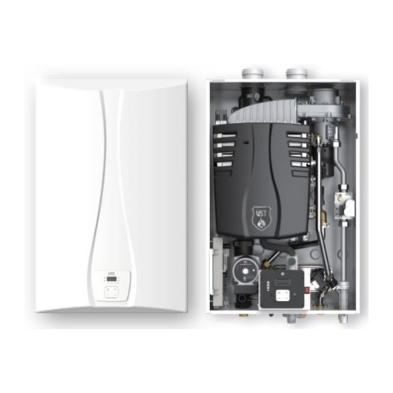
Page 10: Components
Components Flue connector Air intake connector Exhaust temperature sensor Burner hood Gas connector Deco cover Gas valve Pressure sensor Air vent Pump 3-way valve Condensate drain Space heating supply Gas inlet Space heating return Cold water inlet Hot water outlet Installation Manual... - Page 11 Turbo fan assembly Ignition transformer Primary heat TDR damper exchanger Secondary heat exchanger Pressure sensor Air Pressure Sensor PCB assembly Flow sensor Front panel General Information...
-
Page 12: Installing The Boiler
Installing the Boiler Installer Qualifications Humidity and contact with water Avoid places with excessive humidity. The boiler has electric gas A licensed professional must install and inspect the appliance. A ignition components. If water gets inside the boiler, the ignition licensed professional is a person who is licensed for the following: system can be damaged. - Page 13 Clearances Clean, debris and chemical-free combustion The boiler should be installed in an area that allows for service and maintenance access to utility connections, piping, filters, and traps. • Do not install the boiler in areas where dust and debris may Ensure the following clearances are maintained: accumulate or where combustion air can be contaminated.
-
Page 14: Mounting To The Wall
Mounting to the wall • The boiler is heavy. Always lift the unit with assitance. Be careful not to drop the bolier while lifting or handling it to To mount the boiler to the wall: avoid bodily injury or damage to the unit. Warning •... -
Page 15: Installing The System Piping
When installing the VESTA DS boiler and keeping the existing pipes, all pipes including the radiator should be cleaned. • VESTA DS VRC boiler is intended solely for use in a pressurized closed loop heating system operating with 7-30psi water If you fail to remove the above-mentioned contaminants pressure at the boiler outlet. -
Page 16: Backflow Preventer
When replacing the expansion tank, refer to the literature of the Internal LWCO expansion tank manufacturer for selecting the proper size. The VESTA DS VRC boiler already has a type of low water cut off • When installing the diaphragm expansion tank, always install (LWCO) device that senses the pressure inside of the product. -
Page 17: Installing A Domestic Hot Water(Dhw) System
Guidelines for a DHW System water, domestic hot water may scatter or splash onto other equipment around. Connect the pressure relief valve to the VESTA DS VRC boiler is designed to use space heating and domestic outlet pipe. hot water. - Page 18 Copper 1.0 mg/l DHW Filter Iron 0.3 mg/l VESTA DS VRC boiler has a filter on its cold water inlet nipple. Clean Manganese 0.05 mg/l the filter periodically to prevent the interruption of water flow by foreign matters. 6.5 – 8.5...
- Page 19 If the pressure relief valve discharges hot water periodically, it • VESTA DS recommends the use of unions and manual shut-off may be caused by thermal expansion of the closed water system. valves for the cold water inlet and DHW outlet.
-
Page 20: Connection The Condensate Drain
Connection the Condensate Drain Notice • If you choose this option, the neutralizing agent must be replaced • All condensate must drain and be disposed of according to periodically. Depletion of the neutralizing agent will vary, based on local codes. the usage rate of the boiler. -
Page 21: System Filling
Built-in water filling unless filled with water prior to operation. Pour more than 0.1 gallon VESTA DS VRC boiler is designed to fill the system with water. (400 ml) of water into the exhaust duct. Defate air sufficiently or Therefore, additional water fill connection is not necessary in most equip the air vent with an outlet pipe prior to flling the condensate cases. -
Page 22: Test The Water System
Notice VESTA VRC boiler has an air vent inside the product in order to purge air in the system. Installation Manual... - Page 23 Expansion Tank The size of expansion tank should be decided according to the boiler capacity and the amount of water in the system. It is important to locate the expansion tank, and make-up water fill, on the inlet side of any circulator in the system, as doing so will guarantee the lowest pressure in the system will be at least equal to the tank and make-up water pressure.
- Page 24 System Application – Zone System with Circulators Zone 1 Zone 2 Zone 3 Check Valve System pump Air Separator Not exceed Max.12 in Expansion tank Installation Manual...
-
Page 25: Connecting The Gas Supply
Connecting the Gas Supply Gas Pipe Sizing Tables Gas pipe sizing is based on the gas type, supplied gas pressure, pressure drop in the system, and gas line type. The tables below are for reference only (when the gas supply is piping straight to the boiler with no connections to any other gas appliances). For gas pipe sizing, refer to the latest National Fuel Gas code, NFPA 54 and consult the gas pipe manufacturer for actual gas pipe capacities. -
Page 26: Gas Piping
• Leak test the appliance and its gas connection before operating the boiler. • Do not attempt a field conversion without a VESTA.DS conversion kit. Use the VESTA.DS conversion kit to convert from natural gas to propane or vice versa. Failure to do so may result in dangerous operating conditions and will void Check for gas leaks at all joints. -
Page 27: Inlet Gas Pressure
Inlet Gas Pressure • The following is a LP gas piping example for the single regulator system Inlet gas pressure should be measured by a licensed professional only. The boiler cannot function properly without Warning sufficient inlet gas pressure. • The boiler must be isolated from the gas supply piping system during any pressure testing of that system at test pressures equal to or more than 0.5 psig. - Page 28 Remove the boiler front cover by loosening the 2 Phillips When the boiler reaches its maximum firing rate, check the screws securing it to the case. inlet gas pressure reading on the manometer. The gas pressure must fall within the ranges specifed in "Specifications" on page Tighten the inlet gas pressure screw.
-
Page 29: Installing A Vent
DS recommends direct air vent installations whenever possible latest version of the CAN/CGA B149.1 Natural Gas and Propane to avoid back drafting cold air through the boiler. VESTA.DS Installation Code in Canada, as well as all applicable local recommends direct air vent installations when installing the boiler building codes and regulations. - Page 30 IN S ID E D E T A IL C O R N E R F IX E D C L O S E D O P E R A B F IX E D C L O S E D O P E R A B VENT TERMINAL AIR SUPPLY INLET...
- Page 31 VESTA.DS warranty. If there is any question about the possibility of back-drafting in the installation location, use a direct venting system for the boiler.
- Page 32 IN S ID E D E T A IL C O R N E R F IX E D C L O S E D O P E R A B F IX E D C L O S E D O P E R A B VENT TERMINAL AIR SUPPLY INLET...
-
Page 33: Vent Pipe Materials
• This boiler has a built-in control to limit the exhaust temperature to 158°F (70°C). As a result, the VESTA.DS boiler Notice can be vented with Schedule 40 PVC. Caution •... -
Page 34: Connecting The Vent Clip
Connecting the Vent Clip Vent Termination • Air intake must be protected from any debris. To connect the exhaust vent frmly, must use the vent clip • When connecting the air intake connector and the flue included with boiler. Caution Caution connector with the vent, connecting parts must be sealed with PVC, glue and high temp silicon. - Page 35 Two-pipe sidewall venting Snorkel flue Internal view Exhaust gas 10" (254 mm) min. Intake air Schedule 40 PVC pipe 12" (300 mm) min. 10" min. External view • Maintain 12" (300 mm) min. (18" (450 mm) min. for Canada) clearance above highest-anticipated snow level. Maximum 12"...
- Page 36 Non-concentric sidewall venting Two-pipe vertical venting 36" (900 mm) min. Exhaust gas Intake air 12" (300 mm) min. From any obstruction 10" (254 mm) min. (above, below, left, or right) • Maintain 12" (300 mm) min. (18" (450 mm) min. for Canada) •...
-
Page 37: Setting The Dip Switches
Setting the DIP Switches The boiler has a DIP switch on the main circuit board(PCB) Set the DIP switch appropriately, depending on the installation environment. Switch Function ON: No temperature limit for exhaust gas Temperature limit switch for exhaust gas OFF: Temperature limit for exhaust gas ON: Enable EEP ROM data change EEP ROM data change switch... -
Page 38: Connecting The Power Supply
Connecting the Power Supply When connecting the power supply, follow these guidelines: Improperly connecting the power supply can result in electrical shock and electrocution. Follow all applicable • Do not connect the electric supply until all plumbing and gas electrical codes of the local authority having jurisdiction. In Warning piping is complete and the boiler has been filled with water. -
Page 39: Installation Checklist
Installation Checklist After the boiler installation, examine the following checklist. If you are not able to answer "Yes" to all of the items in the checklist, review the appropriate sections. To troubleshoot any operational problems, refer to "Troubleshooting" in the User's Manual. If there are additional questions or if you need assistance, contact technical support at 1-800-761-0053. - Page 40 Connecting the Domestic Water Supply Check Is the water supply pressure sufficient (greater than 40 psi)? Have you installed shut off valves on the inlet and outlet to facilitate cleaning of the inlet water filter? Have you bled the air out at each fixture? Have you checked each fixture to ensure hot water is being supplied? Have you cleaned the inlet water filter? If you installed a recirculation line, have you insulated the hot water pipes and the return line?
- Page 41 Connecting the Condensate Drain Check Have you installed a condensate drain line from the boiler to a drain or laundry tub? Venting the boiler Check Have you vented the boiler with 2/3 in PVC, CPVC, Polypropylene, Type BH Special Gas Vent (ULC-S636) for Category IV boilers (Canada), or in accordance with all local codes and the guidelines in this manual? Have you ensured that ABS or PVC cellular core pipe has not been used as venting for the boiler? Is the vent sloped upward toward the vent termination at a rate of 1/4 in per foot (2% grade)?
-
Page 42: Operating The Boiler
Operating the Boiler Turning the Boiler On or Off Setting the Space Heating Temperature To turn the Boiler on or off, press the button. If your household includes children, or elderly or disabled individuals, consider using a lower temperature setting. Danger To set the space heating water temperature. -
Page 43: Temperature
Setting the DHW(Domestic Hot Viewing Basic Information Water) Temperature To turn the boiler on, press the button. Water above 120°F (50°C) can cause instant scalding, severe burns, or death. Caution To adjust the water temperature: Press the Mode button until the icon turns on. - Page 44 • • This is the mode for checking the previous error. This is the mode for checking the current error. • • H0 and the previous error (example: A6) will be displayed H2 and the current error (Example : A3) will be displayed repeatedly on the screen.
- Page 45 • This is the mode for checking the current number of revolutions • This is the mode for checking the current exhaust gas of the fan. temperature. • H4 and the current number of revolutions of the fan (Example : •...
- Page 46 • • This is the mode for checking the current ambient temperature. This is the mode for checking the hot water and heating modes. • • H8 and the current ambient temperature (example: 25) will be HA and the heating mode or the hot water mode (example: FF displayed repeatedly on the screen.
-
Page 47: Setting The Heat Load For The Outdoor Reset Control Mode
Setting the Heat Load for The • When you set ON for C7 and press the MODE button, C8 and “1” will be displayed repeatedly. Outdoor Reset Control Mode • You can set a value from 0 to 6 using the buttons. - Page 48 • When “6”(custom mode) is set for C8, the user can set the temperature. • By pressing the MODE button, the user can enter modes such as C9, CA, Cb, and CC, and can set the temperature. • The content of each mode is as follows. •...
-
Page 49: Appendix
Danger cause a gas leak, resulting in severe personal injury or death. This conversion kit shall be installed by a qualified service agency* in accordance with VESTA.DS instructions and all applicable codes and requirements of the authority having Warning jurisdiction. The information in these instructions must be followed to minimize the risk of fire or explosion and/ or to prevent property damage, personal injury or death. - Page 50 Once the front cover is removed, place it in a safe location to Once the gas orifice is exposed, remove the screw that hold prevent accidental damage. With the internal components the gas orifice in place and remove the gas orifice from its exposed, locate the gas connector and the gas valve.
- Page 51 Replace the gas connector and the gas inlet pipe to its original Insert analyzer into the exhaust analyzer hole and measure the position and secure all connections. gas/air ratio (using combustion analyzer is recommended). High fire Low fire Turn on the gas and water supply to the boiler. Type Set the DIP switch to minimum heat capacity operation.
- Page 52 Set the DIP switch to maximum heat capacity operation. Be sure to turn off the power before changing the DIP switch setting. Danger Notice For more information about setting the DIP switches, refer to "Setting the DIP Switches" on page 37. Fully open several hot water fixtures and if the CO value at high fire is not within 0.5% of the value listed in the table...
-
Page 53: Wiring Diagram
Wiring Diagram Wiring Diagram... -
Page 54: Component Assembly Diagrams And Parts Lists
Component Assembly Diagrams and Parts Lists Case Parts (VRC) 117 108 Installation Manual... - Page 55 2081156 PCB assembly (VRC-120) 2081157 PCB assembly (VRC-100) 2081158 PCB assembly (VRC-80) 2100363 Air pressure switch (VRC-140, VRC-120) 2100377 Air pressure switch (VRC-100) 2100376 Air pressure switch (VRC-80) 3011632 R/C support bracket 3011565 R/C fixing bracket 2081154 R/C assembly 2010619...
-
Page 56: Flue Parts (Vrc)
Flue Parts (VRC) Installation Manual... - Page 57 Part NO Part Name 3050114 Heat exchager fixing bracket (L) 3050115 Heat exchager fixing bracket (R) 3100192 M4 x 0.7p (L=20) Screw + Washer 2081069 Ignition Transformer 2130507 Burner hood assembly 3090366 Burner Hood & HEX gasket 2020414 Burner aseembly 2070710 Primary heat exchanger assembly (VRC, VRB) 3011670...
- Page 58 Part NO Part Name 3080263 Gas connector packing 3011624 LNG orifce 3011587 LPG orifce 3100198 M3 x 0.5p Screw 3050111 TDR damper body 3100184 M4 x 8 Screw 3050110 Solenoid valve fixing body 3100051 Ø4 x 10 Tapping screw 2030290 Solenoid valve assembly 3040650 Air mixer...
-
Page 59: Water Parts (Vrc Model)
Water Parts (VRC Model) Component Assembly Diagrams and Parts Lists... - Page 60 Part NO Part Name 2091134 Primaty & Secondary HEX connect pipe (VRC, VRB) 3080140 P18 Back Up ring 3011010 Joint clip (16A) 2081032 Temperature sensor (Ø14) 3030260 Supply elbow(VRC,B) 3100053 Ø3.5 x 6 Tapping screw 2080390 Overheat prevent sensor (105 °C) 3011614 Overheat prevent sensor bracket 2091131...
-
Page 61: Outdoor Temperature Senor Installation
Outdoor Temperature Sensor Installation Outdoor Temperature Sensor Outdoor Reset Control (Optional) (Available with Optional Outdoor Temperature Sensor) Outdoor Temperature Sensor Installation The outdoor reset control can be used in order to improve the • Separate the sensor body from the sensor cap. energy efficiency. - Page 62 Memo...
- Page 63 Memo...
- Page 64 VESTA.DS, Inc. 2711 LBJ Fwy Suite#320, Farmers branch, TX 75234 For Technical Support 1-800-761-0053 www.vestahws.com Ver. 1.0...
Need help?
Do you have a question about the VRC-100 and is the answer not in the manual?
Questions and answers