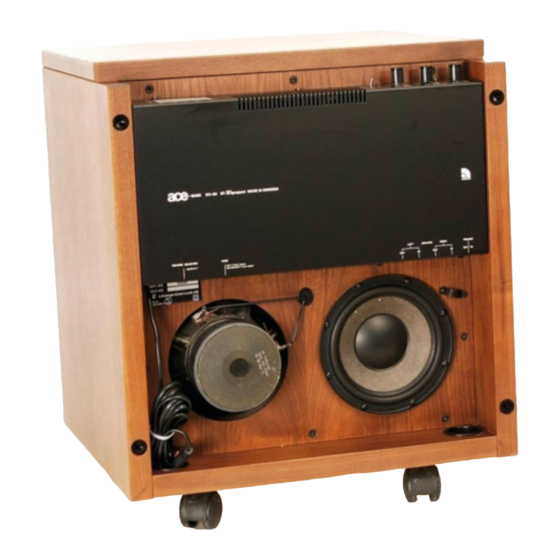
Advertisement
Advertisement
Table of Contents

Subscribe to Our Youtube Channel
Summary of Contents for Audio Pro B2-50
- Page 1 SERVICE MANUAL SUBWOOFER B2-50 Audio Pro AB...
- Page 2 2.1 B2-50 Does Not Work 2.2 Fuses F501, F502 Blow 2.3 Automatic ON/OFF Faulty 2.4 B2-50 Goes On and Off Repeatedly with no signal in. ADJUSTMENTS 3.1 Bias Adjustment in Power Amplifier 3.2 Negative Output Resistance (Rs) in Ace-Bass Amplifier...
-
Page 3: Technical Description
(10-100mV) on its output terminals under operating conditions. If the B2-50 is tested without any load on the Power Amplifier, or with fuses F501, F502 removed, the balance between +15 V and -15 V may be upset during on/off switching. In such cases the operational amplifiers may start oscillating when power is dis- connected, so that Automatic ON is actuated. - Page 4 This circuit is powered via diodes D201, D202 and capacitor C201. The power transformer and the Automatic ON/OFF circuit are powered at all times when B2-50 is plugged in to a live outlet. The other circuits in B2-50 are powered only when relay K101 is actuated.
-
Page 5: Input Stage
1.3 Input Stage The audio signals on DIN plug J303 pin 1 (left channel) and pin 4 (right channel) pass through variable high pass filters formed by C303, R315, R317 and C304 R316, R317 and buffer amplifiers Z301 (5, 6, 7) and Z301 (3 ,2, 1) to DIN plug J303 pins 3 and 5. - Page 6 1.5 Ace-Bass Circuits The Power Amplifier together with Z401 (1, 2, 3) and Z401 (12, 13, 14) form the Ace-Bass amplifier, which can be represented by the diagram below. R418 and Z401 (12, 13, 14) sense the current through the drivers. The voltage in test point (J) equals the driver current (1V/1A).
- Page 7 V510 and V511 filter the supply voltages to the input stages, removing hum and transients. NOTE: If there is a"click" in B2-50 when it is switched on, the cause could be a short circuit in one of the tran- sistors V510, V511.
-
Page 8: Trouble Shooting Tips
2. TROUBLE SHOOTING TIPS Use + pole of C104 or - pole of C103 as common point for measurements of DC or AC voltages. 2.1 B2-50 Does Not Work Set toggle switch in ON position. 2.1-1 Check that LEDs AUTO and ON are lit. -
Page 9: Fuses F501, F502 Blow
Shunt R210 by 100k ohm to shorten off - delay. Check that ON is actuated when signal from generator exceeds .5mV at 500Hz. 2.4 B2-50 Oscillates Between ON and OFF with no audio signal on input. 2.4-1 Check DC offset at test point (G). Should be between +10mV and +100mV. -
Page 10: Adjustments
B2-50). Adjust trimpot Rqc (R525) till voltage reads 22mV. (This corresponds to a bias current of 50mA). Make final adjustment after B2-50 has been ON for a few minutes, so the bias current has reached steady state value. NOTE:... -
Page 11: Negative Output Resistance (Rs) In Ace-Bass Amplifier
3.2 Negative Output Resistance (Rs) in Ace-Bass Amplifier Whenever a driver element or any of resistors R413 - R418 in the current sensing circuit has been replaced, the negative output resistance must be reset to equal the positive resistance of the parallel voice coils in the drivers. 3.2-1 Set jumper below trimpots in position "TRIM", and dis- connect one speaker cable from the circuit board. - Page 12 3.2-6 Check for correct setting of Rrs as follows: Push the cone of forward facing driver inwards, and release it suddenly. Compare the movement of the cone with the curve below, and fine-adjust Rrs if required.
-
Page 13: Spare Parts
4. SPARE PARTS Spare parts for B2-50 can be obtained from the factories, or from Distributors and Service Centers per separate listing. When ordering spare parts, please refer to serial number of B2-50, and component number per diagram 2-125 010.


Need help?
Do you have a question about the B2-50 and is the answer not in the manual?
Questions and answers