Table of Contents
Advertisement
Quick Links
Advertisement
Table of Contents

Related Manuals for Audio Pro B2-70


Summary of Contents for Audio Pro B2-70
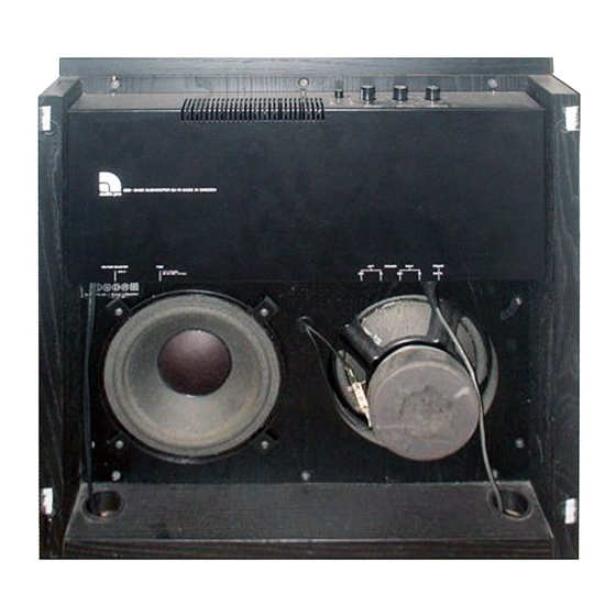
- Page 1 SERVICE MANUAL SUBWOOFER B2-70 Audio Pro AB...
-
Page 2: Table Of Contents
ACE-Bass circuits Power amplifier 2. TROUBLE SHOOTING TIPS B2.70 Does not work Fuses F501, F502 blow Automatic ON/OFF faulty B2-70 oscillates 3. ADJUSTMENTS Bias current in Power Amplifier Negative output resistance 4. SPARE PARTS 5. ENCLOSURES Circuit diagram 55 21295-01... -
Page 3: Technical Description
( 10-100mV ) on its output terminals under operating conditions. If the B2-70 is tested without any load on the Power Amplifier, or with fuses F501, F502 removed, the balance between +15V and -15V may be upset during on/off switching. In such cases the operatio- nal amplifier may start oscillating when power is disconnected, so that automatic ON is actuated. -
Page 4: Automatic On/Off
This circuit is powered via diodes D201, D202 and capacitor C201. The power transformer and the Automatic ON/OFF circuit are powered at all times when B2-70 is plugged into a live outlet. The other circuits in B2-70 are powered only when relay K101 is actuated. -
Page 5: Filter
1.4 Filter The signal from Z301 pin 7 (test point C) passes a variable low pass filter including R401, R402, R403, C401, C402, and Z401 (9,10,8), and then on to a fixed high filter with kneepoint 20.8Hz. The output terminal is test point (E). Remaining components in the filter circuits are part of the ACE-Bass amplifier, and is described in section 1.5. -
Page 6: Power Amplifier
V510 and V511 filter the supply voltages to the input stages, removing hum and transients. NOTE: If there is a"click" in B2-70 when it is switched on, the cause could be a short circuit in one of the tran- sistors V510, V511. -
Page 7: Trouble Shooting Tips
2. TROUBLE SHOOTING TIPS Use J07 or J08 as common point for measurements of DC or AC voltages. 2.1 B2-70 Does Not Work Set push button switch in ON position. 2.1-1 Check that LEDs AUTO and ON are lit. 2.1-2 Check power fuse and fuses F501, F502. -
Page 8: Fuses F501, F502 Blow
2.3-3 Shunt R210 by 100k ohm shorten off - delay. Check that ON is actuated when signal from generator exceeds 0.5mV at 500Hz. 2.4 B2-70 Oscillates B2-70 Oscillates between ON and OFF with no audio signal on input. 2.4-1 Check DC offset at test point (G). Should be between +10mV and +100mV. -
Page 9: Adjustments
(no signal on input terminals of B2-70). Adjust trimpot (R525) till voltage reads 10-15mV. (This corresponds to a bias current of 50mA). Make final adjustment after B2-70 has been ON for a few minutes, so the bias current has reached steady state value. - Page 10 NOTE1:Voice coils of drivers must be at room temperature when Rrs is set. NOTE2:Voltages in 3.2-3 and 3.2-4 are correct. Negative output impedance of ACE-Bass amplifier makes output voltage larger when amplifier load increases. 3.2-5 Reset jumper in "RUN" position. NOTE: Do not touch trimpot Ra (R410).
-
Page 11: Spare Parts
4. SPARE PARTS Spare parts for B2-70 can be obtained from distributors and service centers. When ordering spare parts, please refer to component number per diagram 55 21295-01.
Need help?
Do you have a question about the B2-70 and is the answer not in the manual?
Questions and answers