Advertisement
Quick Links
Advertisement

Related Manuals for Grundfos RF2


Summary of Contents for Grundfos RF2
- Page 1 GRUNDFOS INSTRUCTIONS Redi-Flo Variable Frequency Drive USA Installation and operating instructions...
- Page 2 SAFETY NOTICE This equipment contains voltages that may be as great as 1000 volts! Electrical shock can cause serious or fatal injury. Only qualified personnel should attempt the start–up procedure or troubleshoot this equipment. P P R R E E C C A A U U T T I I O O N N S S : : W W A A R R N N I I N N G G : : Do not touch any circuit board, power device or electrical connection before you first ensure that power has been...
- Page 3 Q Q U U I I C C K K S S T T A A R R T T G G U U I I D D E E To operate the Redi-Flo VFD system, simply: 1. Submerge the RF2 or RF4 pump in the water to be pumped. 2. Connect the motor lead to the Redi-Flo VFD. (Note: With RF4 Variable Performance Pumps you must have an adapter cord to connect to Redi-Flo VFD.
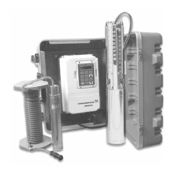
- Page 4 PRE-INSTALLATION CHECKLIST C C o o m m p p o o n n e e n n t t s s o o f f Y Y o o u u r r R R e e d d i i -F F l l o o V V F F D D S S y y s s t t e e m m Your Redi-Flo Variable Performance Pump system should contain the following components: 1.
- Page 5 ASSEMBLING THE REDI-FLO VFD SYSTEM I I N N P P U U T T P P O O W W E E R R T T E E R R M M I I N N A A L L S S The input voltage can be changed between 115V and 230V by changing the line input connections as shown below: W W a a r r n n i i n n g g - I I f f t t h h e e R R e e d d i i -F F l l o o V V F F D D i i s s m m i i s s w w i i r r e e d d f f o o r r t t h h e e i i n n c c o o m m i i n n g g v v o o l l t t a a g g e e , , i i n n t t e e r r n n a a l l d d a a m m a a g g e e...
- Page 6 ASSEMBLING THE REDI-FLO VFD SYSTEM O O P P E E R R A A T T I I N N G G C C O O N N D D I I T T I I O O N N S S To ensure the Redi-Flo Variable Performance Pumping system operates properly, follow these guidelines: •...
- Page 7 REDI-FLO VFD SPECIAL FEATURES D D u u a a l l I I n n p p u u t t C C a a p p a a b b i i l l i i t t y y Redi-Flo VFD can accept 115V or 230V single phase input voltage.
- Page 8 REDI-FLO VFD KEYPAD OVERVIEW O O v v e e r r v v i i e e w w The keypad is used to program the control parameters, to operate the motor and to monitor the status and outputs of the control by accessing the display options, diagnostic menus and the fault log. I I n n d d i i c c a a t t o o r r L L i i g g h h t t s s JOG - (Green) lights when Jog is active.
- Page 9 MOTOR CONTROL VIA KEYPAD The Redi-Flo VFD can operate the motor in three (3) different ways from the keypad. 1. Speed adjustment using the Keypad arrow keys 2. Speed adjustment with Keypad entered values 3. JOG Command 1 1 ) ) K K e e y y p p a a d d a a r r r r o o w w s s p p e e e e d d c c o o n n t t r r o o l l Press FWD or REV to select desired direction of motor rotation, then press or hold the up arrow key to increase speed or use the down arrow key...
- Page 10 MOTOR CONTROL VIA KEYPAD A A d d j j u u s s t t i i n n g g D D i i s s p p l l a a y y C C o o n n t t r r a a s s t t When AC power is applied to the VFD, the keypad should display the status of the unit.
- Page 11 PROG MENU A A d d v v a a n n c c e e d d P P r r o o g g r r a a m m m m i i n n g g A password is required for advanced programming features.
- Page 12 TROUBLESHOOTING GUIDE TO ERROR MESSAGES INDICATION POSSIBLE CAUSE CORRECTIVE ACTION Command Select Incorrect operating mode Change Operating Mode in the Level 1 Input block to one that does not programmed. require the expansion board. Need expansion board. Install the correct expansion board for selected operating mode. Bus Overvoltage DECEL Rate set too low a value Lengthen DECEL time.
- Page 13 TROUBLE SHOOTING GUIDE (CONT.) INDICATION POSSIBLE CAUSE CORRECTIVE ACTION HW Desaturation Accel/Decel rate set too short. Lengthen Accel/Decel rate. Torque Boost set too high. Reduce torque boost value. Electrical noise in logic circuits. Check for proper grounding of power wiring and shielding of signal wiring. Motor overloaded.
- Page 14 TROUBLE SHOOTING GUIDE (CONT.) INDICATION POSSIBLE CAUSE CORRECTIVE ACTION New Base ID Replaced Control or circuit board. Restore parameters to factory settings. Reset control. No Display Lack of input voltage. Check input power for proper voltage. Loose connections. Check input power termination. Verify connection of operator keypad.
- Page 15 HOW TO ACCESS DIAGNOSTIC INFORMATION Action Description Display Comments Apply Power Logo display for 5 seconds. Display mode showing Local No faults present. Local keypad redifl2 mode voltage, current & mode. If in remote/serial mode, frequency status. press local for this display. Press DISP key Scroll to fault log block.
- Page 16 HOW TO ACCESS THE FAULT LOG When a fault condition occurs, motor operation stops and a fault code is displayed on the Keypad display. The control keeps a log of the last 31 faults. If more than 31 faults have occurred, the oldest fault will be deleted from the fault log.
- Page 17 FAULT MESSAGES FAULT MESSAGE DESCRIPTION Invalid Base ID Failure to determine control horsepower and input voltage configuration from the Power Base ID value in software. NV Memory Fail Failure to read or write to non-volatile memory. Param Checksum Parameter Checksum error detected. Low INIT Bus V Low bus voltage detected on startup.
-
Page 18: Technical Specifications
TECHNICAL SPECIFICATIONS 01E)D5BF5A@É D2ìÉ D2îÉ Bx‰‹É5É Dx‹|{ÉB†Ž|‰É”É9x‰‚€…~Š 1 X 115V +/- 10% or 1 X 230V +/- 10% Input Voltage Single Phase Input Output Voltage 3 X 220V 3 X 230V Continuous Output Current (230V input) 6.05A 8.25A Continuous Output Current (115V input) 6.05A 6.50A Bx‰‹É55É... - Page 19 WARRANTY SERVICE The Redi-Flo VFD is covered by the original equipment manufacturers warranty for a period of 24 months. To obtain warranty services, contact the distributor or dealer from which it was purchased to obtain instructions. U U n n d d e e r r n n o o c c i i r r c c u u m m s s t t a a n n c c e e s s s s h h o o u u l l d d d d e e f f e e c c t t i i v v e e p p r r o o d d u u c c t t b b e e r r e e t t u u r r n n e e d d t t o o t t h h e e d d i i s s t t r r i i b b u u t t o o r r , , d d e e a a l l e e r r , , o o r r G G R R U U N N D D F F O O S S w w i i t t h h o o u u t t a a r r e e t t u u r r n n m m a a t t e e r r i i a a l l s s a a u u t t h h o o r r i i z z a a t t i i o o n n ( ( R R M M A A ) ) .
- Page 20 Innovation is the essence L-RF-IO-009 Rev. 06/02 Printed in the U.S.A. North American Regional Headquarters Grundfos Canada, Inc. Bombas Grundfos de Mexico, S.A. de C.V. Grundfos Pumps Corporation 2941 Brighton Road Boulevard TLC #15 17100 W. 118th Terrace Oakville, Ontario L6H 6C9, Canada...
Need help?
Do you have a question about the RF2 and is the answer not in the manual?
Questions and answers