Axis Q8685-E Installation Manual
Ptz network camera
Hide thumbs
Also See for Q8685-E:
- Installation manual (306 pages) ,
- User manual (69 pages) ,
- User manual (28 pages)
Table of Contents
Advertisement
Quick Links
Advertisement
Table of Contents

Related Manuals for Axis Q8685-E


Summary of Contents for Axis Q8685-E
- Page 1 AXIS Q8685-E PTZ Network Camera Installation Guide...
- Page 2 Installation Guide Table of Contents Safety information ......... . Hazard levels .
- Page 3 3 . Every care has been taken in the preparation of this • Low Voltage (LVD) Directive 2014/35/EU. See Safety document. Please inform your local Axis office of any on page 4 . inaccuracies or omissions. Axis Communications AB cannot •...
- Page 4 • report problems to Axis support staff by logging in to disposal. Businesses should contact the product supplier for your private support area information about how to dispose of this product correctly.
-
Page 5: Safety Information
AXIS Q8685-E PTZ Network Camera Safety information Hazard levels DANGER Indicates a hazardous situation which, if not avoided, will result in death or serious injury. WARNING Indicates a hazardous situation which, if not avoided, could result in death or serious injury. -
Page 6: Safety Instructions
• Use only spare parts provided by or recommended by Axis. • Do not attempt to repair the product yourself. Contact Axis support or your Axis reseller for service matters. • Do not point the camera lens toward the sun or other high-intensity radiation sources... -
Page 7: Transportation
Battery The Axis product uses a 3.0 V BR2032 lithium battery as the power supply for its internal real-time clock (RTC). Under normal conditions this battery will last for a minimum of five years. Low battery power affects the operation of the RTC, causing it to reset at every power-up. When the battery needs replacing, a log message will appear in the product’s server report. -
Page 9: Package Contents
AXIS Q8685-E PTZ Network Camera Package contents • AXIS Q8685–E PTZ Network Camera • Power connector • I/O connector • Torx® bit T20 and T30 • Printed materials Installation Guide (this document) Extra serial number label (2x) AVHS Authentication key... -
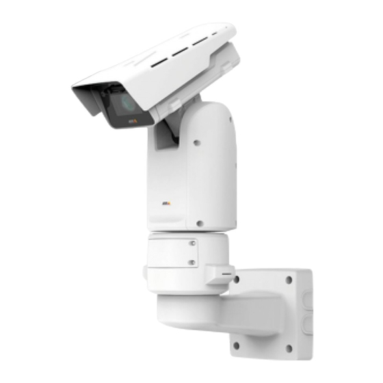
Page 10: Hardware Overview
AXIS Q8685-E PTZ Network Camera Hardware overview For specifications of the hardware components, see Specifications on page 26. Sunshield Top cover Wiper Front window Inner cover Lens Base unit... - Page 11 AXIS Q8685-E PTZ Network Camera Factory default switch SD memory card slot Input power connector I/O connector RJ45 connector SFP slot for SFP module (SFP module not included)
-
Page 12: How To Install The Product
AXIS Q8685-E PTZ Network Camera How to install the product DANGER Risk of electric shock. All cables shall be de-energized before installing the product. CAUTION The electrical connections and conduit installations shall be made by a certified electrician and in compliance with local regulations. -
Page 13: Mount The Base Unit
AXIS Q8685-E PTZ Network Camera Mount the base unit Base unit 1. Remove the four base unit screws (T30). 2. Simultaneously pull and turn the base unit counterclockwise until the arrows on the base unit and the rest of the unit are aligned. - Page 14 AXIS Q8685-E PTZ Network Camera NO TICE TICE TICE Do not use sharp tools when removing the transparent base unit cover. 4. Remove the transparent base unit cover.
-
Page 15: Route The Cables
AXIS Q8685-E PTZ Network Camera Conduit cover clip Conduit cover Screw hole (x4) 5. For conduit installations only: remove the two conduit cover clips followed by the conduit cover. 6. Attach the base unit to the mounting surface using the appropriate fasteners in the four screw holes. - Page 16 AXIS Q8685-E PTZ Network Camera Power cable (not included) Strain relief Grounding screw Grounding braid (not included) Bottom cable hole 1. Install the optional conduit adapters (not included). 2. Connect the grounding braid to the grounding screw. 3. Insert the power cable, I/O cable and network cable through the hole in the base unit as shown in the illustration above.
- Page 17 AXIS Q8685-E PTZ Network Camera I/O cable (optional, not included) Network cable (not included) 5. Insert the I/O cable (optional) through the strain relief with a distance of 420 mm (16½ in) from the strain relief to the end of the cable.
- Page 18 AXIS Q8685-E PTZ Network Camera Power cable (not included) I/O cable (optional, not included) Network cable (not included) Cable gasket Transparent base unit cover 8. Fit cable gaskets on the cables. See Cable thickness on page 29. 9. Insert the power, I/O and network cables including the cable gaskets through the holes in the transparent base unit cover and arrange the cables as shown in the illustration above.
- Page 19 AXIS Q8685-E PTZ Network Camera I/O connector Power connector O-ring NO TICE TICE TICE Make sure the protective earth wire is about 10 mm (3/8 in) longer than the other two wires (in the power cable), so that it will not be disconnected accidentally if pulled.
- Page 20 AXIS Q8685-E PTZ Network Camera 13. Replace the positioning unit on the base unit making sure that the arrows on the two units are aligned. 14. Turn the positioning unit clockwise back to its original position and tighten the four base unit screws (torque 3.0 Nm).
-
Page 21: Install The Network Link
AXIS Q8685-E PTZ Network Camera Install the network link You have different options for installing the network link: • A: via an optical fiber or RJ45 cable connected to the SFP module (with a respective connector) in the SFP slot. -
Page 22: Connect The Cables
AXIS Q8685-E PTZ Network Camera Connect the cables 1. Loosen the four lid screws (T20) and remove the lid. Input power connector I/O connector RJ45 connector SFP slot for SFP module (SFP module not included) 2. Connect the network (optical fibre and/or RJ45), I/O and power cables. For more information on different network connectivity options, see Install the network link on page 21. -
Page 23: Install An Sd Card (Optional)
5. Re-connect power to the product. How to access the product AXIS IP Utility and AXIS Camera Management are recommended methods for finding Axis products on the network and assigning them IP addresses in Windows®. Both applications are free and can be downloaded from axis.com/support... -
Page 24: Reset To Factory Default Settings
AXIS Q8685-E PTZ Network Camera Reset to factory default settings CAUTION Risk of injury. Moving parts. Keep your body parts away from the product when in operation. Disconnect from power supply before installing or performing maintenance on the product. CAUTION Risk of injury. -
Page 25: Further Information
• For useful online trainings and webinars, see axis.com/academy Optional accessories For a complete list of available accessories for this product, go to the product’s page on axis.com and select Software & Accessories. Warranty information For information about Axis’ product warranty and thereto related information, go to... -
Page 26: Specifications
AXIS Q8685-E PTZ Network Camera Specifications To find the latest version of the product’s datasheet, go to the product page on axis.com and locate Support & Documentation. SD card slot CAUTION Risk of injury. Moving parts. Keep your body parts away from the product when in operation. - Page 27 AXIS Q8685-E PTZ Network Camera I/O connector Use the I/O connector with external devices in combination with, for example, motion detection, event triggering, and alarm notifications. In addition to the 0 V DC reference point and power (DC output), the I/O connector provides the interface to: Digital input - For connecting devices that can toggle between an open and closed circuit, for example PIR sensors, door/window contacts, and glass break detectors.
-
Page 28: Power Connector
AXIS Q8685-E PTZ Network Camera DC ground DC output 12 V, max 50 mA I/O configured as input I/O configured as output Configurable I/O Configurable I/O Power connector 4-pin terminal block for power input. 24 V AC/DC power connector NO TICE... -
Page 29: Cables
AXIS Q8685-E PTZ Network Camera This table is only valid for the 24 V AC and the 24 V DC power connectors. (Continued) Position 24 V AC 24 V DC 24 V AC Neutral Not connected Not connected 240 V AC power connector... -
Page 30: Operating Conditions
Max consumption 16 W 204 W Important When using the 22 m (72 ft) AXIS Cable 24 V DC/24–240 V AC, a power supply capable of delivering 400 W is required to compensate for the power loss in the cable. - Page 31 AXIS Q8685-E PTZ Network Camera NO TICE TICE TICE The typical power consumption values are based on the following: • Any losses in the power cable disregarded • No positioning active • No wiper motor active • Temperature at 25 °C / 77 °F (all heaters off) •...
- Page 32 Installation Guide Ver. M3.3 AXIS Q8685-E PTZ Network Camera Date: November 2017 © Axis Communications AB, 2017 Part No. 1797408...
Need help?
Do you have a question about the Q8685-E and is the answer not in the manual?
Questions and answers