
Related Manuals for Dimplex ECS150HP40A-580


Summary of Contents for Dimplex ECS150HP40A-580
- Page 1 A Class Heat Pump Cylinders Up to 250L EC-Eau Cylinder Range Installation and User Instructions Important - This Manual Must Be Left With The User After Installation!
- Page 2 Dimplex is a licensed member of the Benchmark Scheme which aims to improve the standards of installation and commissioning of domestic heating and hot water systems in the UK and to encourage regular servicing to optimise safety, efficiency and performance.
-
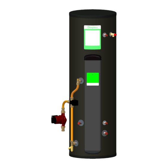
Page 3: Overall View
0 Overall View Figure 1: Overall View of A Class Heat Pump Cylinder Installation Process Overall View... - Page 4 1 Contents 0 Overall View ......................3 1 Contents ........................4 2 Introduction ......................7 3 Scope of Delivery ..................... 7 4 Pre-Installation Advice ..................... 8 Risk Assessment ....................8 Siting Considerations ....................8 Cold Water Supply ....................9 Building Regulation G3 Discharge Requirements ............9 4.4.1 Discharge Pipe D2 ..................9 4.4.2...
- Page 5 7 Maintenance ......................25 8 Spare Parts ......................26 9 Technical Data and Product Fiche ................27 A Class Heat Pump Buffer Range ................27 Cylinder Heat Exchanger Pressure Drop ..............30 Cylinder Attainable Temperature ................31 User Instructions....................31 10.1 General ......................
-
Page 6: Scope Of Delivery
Precaution: This appliance can be used maintenance this by children aged from 8 years and above appliance must be carried out by and persons with reduced physical, a suitably qualified person only. sensory or mental capabilities or lack of It is recommended to maintain experience and knowledge if they have the unit on an annual basis. -
Page 7: Introduction
The package is provided with fittings that comply with Section G3 of Building Regulations. Table 1: Scope of Delivery for A Class Heat Pump Cylinders * These items are supplied factory fitted ** Supplied with Dimplex heat pump hydraulic pack Scope of Delivery... -
Page 8: Pre-Installation Advice
Pre-Installation Advice the user preference must be considered when commissioning system, particular when adjusting the temperature Please read the following section carefully before and timer settings. commencing installation. If in any doubt, please call the appropriate help desk. Disregarding the 4.2 Siting Considerations instructions given in this manual in its entirety and any relevant regulations, standards and... -
Page 9: Cold Water Supply
The cold water inlet pipe work should have performance standard.” at least an inside diameter of 19mm and should meet the requirements of the water Dimplex strongly recommends the use of metal regulations for the supply of wholesome pipework only and Dimplex does not take water. - Page 10 Figure 2: Typical Discharge Pipe Arrangement Table 2: Sizing of Copper Discharge Pipe “D2” for Common Temperature Relief Valve Outlet Sizes Pre-Installation...
-
Page 11: Worked Example
4.4.2 Worked Example they should be either polybutalene (PB) or cross-linked polyethylene (PE-X) complying This example is for a G½ temperature relief valve with national standards. with a discharge pipe (D2) (as fitted on 125 to 300L cylinders) having 4 No. 22mm elbows and ... -
Page 12: Installation
Installation It is important to check the pre-charge pressure expansion vessel membrane before filling the cylinder. This 5.1 Cold Water Inlet with Inlet Control has been factory set to 3 bar. The pre- Group charge should be greater than or equal to 3bar. -
Page 13: Hot Water Outlet
The hot water pipe work is to be directly appropriate sealant (Dimplex part number connected to the hot water outlet connection on R00836-1). -
Page 14: Coil Return Connections
5.6 Coil Return Connections 5.7 Coil Flow Connections If the return connection is the lowest point in the If the flow connection is the highest point in the heat pump loop, a suitable drain device should heat pump loop and if the system was not be installed. - Page 15 Figure 6: Wiring Configuration of Space Heating and Hot Water - Dimplex "A Class" Cylinder Installation...
-
Page 16: Temperature Sensor Connection
5.8.1 Temperature Sensor Connection 5.8.1.1 Temperature Sensor Connection Thermostat Housing Step 1: Access the sensor mounting plate. To do this remove the hood (A) by removing the fixing screws at the bottom sides. Position to mount sensor T3 Position to mount sensor T2 Step 2: Remove the insulation foam (B) to access the sensor mounting plate (C) and remove the M5 fixing screws in the four corners of the plate, when mounting sensor T2. - Page 17 Step 3: Orientate the sensor mounting plate to allow access to the phials (four clips in the centre of the sensor mounting plate). Be careful not to kink the capillaries that connect the thermostat bulbs. The sensor mounting plate will have two vacant slots for additional sensors (D). Repeat for both positions. Step 4: Move the sensor mounting plate back into its fixing position.
- Page 18 Step 4: Replace the insulating foam over the sensor mounting plate. Step 5: Replace the relay assembly (as required) and then refit the hood. Installation...
-
Page 19: Water Module Wiring
5.9 Water Module Wiring 5.9.1 Primary Electrical Connections In both retro fit and new build installations, a 3 All wiring must be carried out by a suitably core cable must be taken from the isolator qualified person and must be fully compliant with [typically a 16Amp double pole fused spur] and current release... -
Page 20: Modbus Connection
5.9.2 Modbus Connection The earth shield of the Modbus connection must be connected to ground at both ends. Correct installation of the Modbus connections is The Earth connector block or the cylinder critical for communication between the heat stat bracket can be used as a ground pump, UI and the cylinder. - Page 21 Figure 9: Zone Connection 5.9.4 Digital Inputs & Temperature • Digital input 1 is a spare connection. Sensors • Digital input pre-wired The water module contains 5 optional digital enables/inhibits remote control. inputs, 4 optional NTC zone temperature sensor inputs and 1 domestic hot water (DHW) NTC •...
-
Page 22: Digital Inputs & Temperature Sensors
Figure 10: Digital Inputs & Temperature Sensors Installation... -
Page 23: Bivalent System
5.10 Bivalent System The secondary return loop must avoid - stagnant water in long pipe runs Bivalent system operation can be achieved by disconnecting the buffer cylinder live connection - long waiting times at draw off point for hot [A] and connecting the backup heat source water 5.11 Connection of Secondary Return - undue water wastage... -
Page 24: Commissioning
Commissioning Check all shower outlets, toilet cisterns and other draw off points for leaks or dripping (especially when replacing a vented unit). At the time of commissioning, complete all Open all water outlets to purge air from relevant sections of the Benchmark Checklist pipe work and ensure proper operation. -
Page 25: Maintenance
Maintenance Periodically the immersion heaters should be removed cleaned and the unit flushed out. Check the O-ring seal for damage and After servicing, complete the relevant Service replace if necessary. Record section of the Benchmark Checklist located on the inside back pages of this Check electrical wiring connections and the document. -
Page 26: Spare Parts
Spare Parts * ECS150HP40A-580 only ** ECS210HP40A-580 only *** ECS250HP40A-580 only Figure 12: Replacement Part Numbers for Heat Pump Range of Cylinders Spare Parts... -
Page 27: Technical Data And Product Fiche
Technical Data and Product Fiche 9.1 A Class Heat Pump Buffer Range Figure 13: A Class Heat Pump Cylinder and Cross-Section (For Reference Only) Technical Data... -
Page 28: Technical Data
Note: All measurements are taken from the base of the cylinder to the mid-point on the item. * Determined in accordance with EN12897 test procedures. A Class Heat Pump Cylinder Range – Product Fiche Reference ECS150HP40A-580 ECS210HP40A-580 ECS250HP40A-580 Energy Rating... - Page 29 A Class Heat Pump Cylinder Range – Product Features Actual capacity [L] 145 + 40 208+40 245 + 40 Materials - inner cylinder Duplex stainless steel LDX2101 - outer cylinder ABS/HIPS - inlet/outlet Stainless steel - coils Stainless steel - insulation 60mm PU foam (GWP=1, ODP=0) Maximum operating conditions 70°C...
-
Page 30: Cylinder Heat Exchanger Pressure Drop
9.2 Cylinder Heat Exchanger Pressure Drop 2.2 m Coil Pressure Drop 14000 12000 10000 8000 6000 4000 2000 Flow Rate (m Figure 14: Heat Exchanger Pressure Drop for 2.2m² Coils Technical Data... -
Page 31: Cylinder Attainable Temperature
9.3 Cylinder Attainable Temperature write the Notification Number on the Benchmark Checklist. heat pump heating system must This product should be serviced annually to commissioned by a trained installer. Ensuring optimise its safety, efficiency and performance. correct installation of the system will allow a The service engineer should complete the water temperature of 60°C to be obtained inside relevant Service Record on the Benchmark... -
Page 32: Maintenance
10.4 Maintenance Dial to adjust water temperature The maintenance of this appliance must be carried out by a suitably Earth (green/yellow) qualified person only. Live (brown) recommended to maintain the unit on Neutral (blue) an annual basis. Isolate all electrical supplies from unit... - Page 33 Figure 16: A Class Cylinder Wiring Overall View Wiring...
- Page 34 Figure 17: A Class Installer Wiring Overall View Wiring...
- Page 35 Notes...
- Page 36 Notes...
- Page 39 Dimplex a division of GDC Group Ltd Millbrook House Grange Drive, Hedge End, Southampton SO30 2DF Tel.: 0845 879 3588 Fax: 0845 879 3583 e-mail: customer.services@gdcgroup.co.uk www.dimplex.co.uk...
Need help?
Do you have a question about the ECS150HP40A-580 and is the answer not in the manual?
Questions and answers