
Related Manuals for EarthLinked Prime Series


Summary of Contents for EarthLinked Prime Series
- Page 1 Prime Series PSC Geothermal Heating and Cooling System Quick-Start Instructions PSC-QS (10/16) ©2016 EarthLinked Technologies, Inc.
-
Page 2: Table Of Contents
2) Compressor Unit Placement ....................8 3) Refrigeration ..........................9 4) System Applications and Electrical ..................13 5) EarthLinked® Diagnostic and Monitoring system (EDM) ............19 6) Air Zoning ..........................19 7) SureStart ..........................21 Earth Loop Protection System ....................... 25 1) Anode Wire Installation ...................... -
Page 3: List Of Figures
List of Figures Figure 1. Matching Component Model Numbers ................... 7 Figure 2. General Layout of System Components ................8 Figure 3. Compressor Unit Bracket Installation ..................9 Figure 4. Compressor Unit Clearance ....................9 Figure 5. PSC Connections ........................ 10 Figure 6. -
Page 4: List Of Revisions
Figure 35. System Troubleshooting Chart ..................48 List of Revisions Corrected Piping and Internal Flow Schematic Revised electrical drawings and electric box Revised charging method due to elimination of TXV Units now feature a nano Programmable Logic Controller (PLC) which allows the following features: ... -
Page 5: M Odel Nomenclature
Earthlinked Technologies shall not be liable for any defect, unsatisfactory performance, damage or loss, whether direct or consequential, relative to the design, manufacture, construction, application or installation of the field specified components. -
Page 6: Safety
Start-Up procedure. Series AVS and AVV Air Handler Series CCS Cased Coil Series HCM Hybrid Cooling Module Earth Loop Specification and Installation Manual Earth Loop Protection Kit Installation Manual EarthLinked Diagnostic and Monitoring system (EDM) Installation Manual PSC-QS (10/16) Page 6... -
Page 7: Installation
Installation Component Matching Upon receipt of the equipment, carefully check the component model numbers by referencing Figure 1, to ensure that all components of the system match. Air Handler Cased Coil Prime Hybrid Earth Arcoaire Arcoaire Compress. Cooling Arcoaire Loop Four Speed Four Speed Variable... -
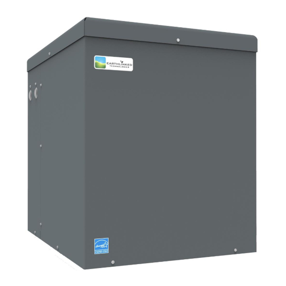
Page 8: Compressor Unit Placement
Compressor Unit Placement ® EarthLinked compressor units may be located inside or outside. If outside, place compressor unit on a standard HVAC outdoor unit pad. If inside, place it on a level, hard surface. If the compressor unit is to be fastened down, see Figure 3 for bracket installation. -
Page 9: Refrigeration
Figure 3. Compressor Unit Bracket Installation Figure 4. Compressor Unit Clearance ® Placement instructions for other pieces of equipment that make up the EarthLinked System are included with those pieces of equipment and are listed in this manual under Equipment Manuals. -
Page 10: Figure 5. Psc Connections
IMPORTANT! ® EarthLinked compressor units that provide space heating shall be equipped with a Heating Performance Enhancement kit (HPE) when required by the performance tables. COMPRESSOR UNIT MODEL TYPE OF CONNECTION SIZE, INCHES PORT FUNCTION CONNECTION -025 -030 -036 -040... - Page 11 Compressor units are shipped from the factory with a low pressure nitrogen holding charge. Carefully relieve the holding charge when the compressor unit is being prepared to connect refrigerant system piping. Caution! This compressor unit is equipped with Copeland Ultra 32-3MAF Polyol Ester Oil (POE).
-
Page 12: Figure 6. Line Set Sizes
The compressor unit has factory installed service valves on the earth loop vapor and liquid stubouts outside the compressor cabinet. For the installation of system components requiring refrigeration connections, refer to Figure 6 for line set sizes and the appropriate installation manual(s) following Figure 6. LINE SET ADAPTERS REQUIRED FOR THE AIR HANDLER OR CASED COIL ARE FIELD SUPPLIED. -
Page 13: System Applications And Electrical
System Applications and Electrical The PSC compressor unit electrical box major components and electric data for all compressor sizes are shown in Figure 7. The PSC series compressor units are equipped with a Nano-PLC (Programmable Logic Controller) to provide a range of functions that enhance the comfort and efficiency of system operation. See the Appendix detailing the PLC Functions for Air Only Systems. -
Page 14: Figure 7. Psc Electric Box Components & Electrical Data
Single Phase Electric Box Voltage Compressor Compressor Voltage/Phase/ Unit Model Model Min. Max. -025-1C ZPS26K5E-PFV 230-1-60 73.0 14.6 18.0 -025-2C ZPS26K5E-TF5 230-3-60 58.0 12.0 -030-1C ZPS30K5E-PFV 230-1-60 83.0 17.0 21.0 -030-2C ZPS30K5E-TF5 230-3-60 73.0 12.9 16.0 -036-1C ZPS35K5E-PFV 230-1-60 96.0 20.0 25.0 -036-2C... -
Page 15: Figure 8A. Psc Compressor Electrical Schematic, 230-1-60
Figure 8a. PSC Compressor Electrical Schematic, 230-1-60 PSC-QS (10/16) Page 15... - Page 16 Figure 8b. PSC Compressor Unit Electrical Schematic, 230-3-60 PSC-QS (10/16) Page 16...
- Page 17 Figure 9. PSC Air Heating/Cooling System Application PSC-QS (10/16) Page 17...
- Page 18 Figure 10. PSC Air Heating/Cooling System Field Wiring Diagram PSC-QS (10/16) Page 18...
-
Page 19: Earthlinked® Diagnostic And Monitoring System (Edm)
Sensors are already connected to respective components and the system will begin collecting data at unit startup. The EDM system has the ability to send data remotely to the Earthlinked online Dealer Dashboard when connected to the homeowner’s internet router with an Ethernet cable. -
Page 20: Figure 11. Air Zoning Option Kit, Field Wiring Diagram
The Air Zoning Option kit is designed to use the Damper Override “D” terminal signal of the compressor unit to force open the largest zone while the EarthLinked system is in maintenance mode. The kit isolates the zone control and air handler power supplies and ensures system performance and reliability by providing a means of making “R”... -
Page 21: Surestart
SureStart Features SureStart is a factory installed soft starter that reduces light flicker caused at start-up by scroll compressor motors. This control has the following features: 60 to 70% reduction in direct in-rush current Under voltage protection Motor reversal protection ... -
Page 22: Figure 12. Surestart Mode Of Operation
If the run capacitor is faulty or has failed, SureStart will shut down the compressor for 3 minutes before initiating a restart. Figure 12. SureStart Mode of Operation PSC-QS (10/16) Page 22... - Page 23 Flash Codes – Single Phase LED Flash Codes A Red LED indicator will flash under the following conditions. [NOTE: LED fault indicator is turned off in normal running mode.] a) Rapid Flash (10 / sec) : Low Voltage b) Triple Flash Every Three Seconds (3 / 3 secs): Lockout on Three Failed Starts c) Slow Flash (1 / 3 secs): Lockout on Over Current d) Slow Steady Flash (1 / sec): Cycle Delay / Fault Mode Flash Code (Rapid Flash (10 / sec) : Low Voltage)
- Page 24 Flash Codes – Three Phase A Red LED indicator will flash under the following conditions. [NOTE: LED fault indicator is turned off in normal running mode.] a) Reverse Phase: (1 / 2 secs) b) Fault Mode/Cycle Delay: (1 / 4 secs) c) Low Voltage/Over Voltage: 2 / 2 secs) Flash Code (Reverse Phase: (1 / 2 secs)) Displayed if the supply “Phase Sequence”...
-
Page 25: Earth Loop Protection System
WARNING! ® All power of the EarthLinked System is to be shut OFF at the disconnect while field wiring the Earth Loop Protection System. Failure to do so may result in serious injury or death, or equipment or property damage. -
Page 26: Figure 14. Disassembled Plug Connector
Figure 14. Disassembled Plug Connector PSC-QS (10/16) Page 26... -
Page 27: Figure 15. Anode Wire Insertion
Strip the insulation from the multi-strand anode wire back approximately ¾ inch from the end and while keeping the strands together, push the anode wire through the gland nut, gland cage, gland and plug body as shown in Figure 15. Loosen one of the two screw terminals on the plug insert to receive all of the strands of anode wire on one terminal. -
Page 28: Figure 16. Install The Plug Insert
Figure 16. Install the Plug Insert Slide the gland forward on the anode wire until it is firmly seated in the plug body as shown in Figure 17. Next, slide the gland cage over the gland, and slide the gland nut firmly against the gland cage, with the gland nut against the plug body. -
Page 29: Figure 18. Secure The Anode Wire
Once the gland nut has been hand tightened into the plug body, use two adjustable wrenches to further tighten the gland nut until it is snug in the plug body as shown in Figure 18 and the anode wire is held firmly in the plug body and will not slip out. Do not over-tighten the gland nut! Figure 18. -
Page 30: Eps Operation And Service
2) EPS Operation and Service Reference Figure 20 for the EPS components in the compressor unit electric box. Figure 20. Electric Box with EPS Components With power ON, and viewing the EPS Module (under the EDM system in the compressor unit electric box), the EPS green light should be illuminated, indicating there is power to the EPS system. -
Page 31: Current Verification
3) Current Verification If it is necessary to verify the current flow through the EPS system, it can be checked with a digital DC ammeter set on the Milliampere scale. The correct electrical currents for nominal system capacities are listed in Figure 21. Nominal System Capacity, Tons Current Rating 1.5 thru 2.5... -
Page 32: Start-Up Process
CAUTION! During the Evacuation and Initial Charging processes, be sure that ALL ® power to the EarthLinked System is OFF. This includes the compressor unit, air handler and all other electrically powered system components. Failure to do so will cause lockout on start-up. -
Page 33: Figure 23. Psc Internal Flow Schematic
Figure 23. PSC Internal Flow Schematic PSC-QS (10/16) Page 33... -
Page 34: Figure 24. Psc Piping
Figure 24. PSC Piping PSC-QS (10/16) Page 34... -
Page 35: Evacuation
2) Evacuation Refer to Figure 25 and the following procedure: 1. Carefully vent any pressurized nitrogen charge from the compressor unit and system.. 2. After venting the pressurized system, use a good quality gauge manifold and a non-permeable hose set as shown in Figure 25. If possible, use two Schrader core removal tools. Install one on the discharge line access port and the other on the initial charging port. -
Page 36: Figure 25. Evacuation Of Psc System
Figure 25. Evacuation of PSC System PSC-QS (10/16) Page 36... -
Page 37: Initial Charge
3) Initial Charge 1. Disconnect the vacuum pump and isolate the digital vacuum gauge. Connect the refrigerant container to the charging hose of the manifold gauge set as shown in Figure 26. WARNING! Inhalation of high concentrations of refrigerant gas vapor is harmful and may cause heart irregularities or death. -
Page 38: Figure 26. Initial Charge Of Psc System
Figure 26. Initial Charge of PSC System PSC-QS (10/16) Page 38... -
Page 39: Final Charge
4) Final Charge 1. Remove the Schrader core tool from the hose just taken off of the initial charging port. 2. Crack open the LP valve on the manifold gauge set so that a small amount of refrigerant gas flows to purge the hose. Connect the hose to the final charging port, shown in Figure 27. Tighten the hose to the final charging port and turn off the LP valve when the hose connection is secure. -
Page 40: Figure 27. Final Charge Of Psc System
Figure 27. Final Charge of PSC System PSC-QS (10/16) Page 40... -
Page 41: Figure 28. Charging To The Middle Sight Glass (Heat Only Units)
Figure 28. Charging to the Middle Sight Glass (Heat only units) Figure 29. Final charging to the Top Sight Glass (Heat/Cool units) PSC-QS (10/16) Page 41... -
Page 42: Figure 30. Pressure-Temperature For R-410A
TEMPERATURE PRESSURE TEMPERATURE PRESSURE (°F) (psig) (°F) (psig) 26.1 199.2 30.8 216.1 35.9 234.0 41.5 253.0 47.5 273.0 54.1 294.1 61.2 316.4 68.8 339.9 77.1 364.6 86.0 390.5 95.5 417.7 105.7 446.3 116.6 476.3 128.3 507.6 140.8 540.5 154.1 574.8 168.2 610.6 183.2... -
Page 43: Figure 31. Start-Up Process
Figure 31. Start-Up Process PSC-QS (10/16) Page 43... -
Page 44: Troubleshooting
AND OR FAIL, 2) PROPERTY DAMAGE, INJURY OR DEATH. IMPORTANT! EarthLinked® Refrigerant System Safety Switches EarthLinked® compressor units are equipped with the following three safety switches that will turn the compressor off if the following limits are exceeded. High Pressure Switch: Located between the compressor discharge port and the reversing valve, the cut-out pressure is 600 psig. -
Page 45: Figure 32. Compressor Unit Voltage Information
Figure 32. Compressor Unit Voltage Information The following compressor checklist is provided to analyze the compressor and determine if it is operating properly or if it is faulty: 1. Electrical Service Panel – turn power off. a. Check circuit terminal connections for tightness b. -
Page 46: Figure 33. Compressor Motor Circuit Testing
If the compressor draws a high amperage and does not start (amperage is approximately locked rotor amperage – LRA (See Figure 7)), the compressor is locked mechanically and should be removed from the system and replaced. Verify before removing! 7. Motor Circuit Testing Using a digital volt-ohmmeter (VOM), measure the resistance across the compressor windings terminals as shown in Figure 33. -
Page 47: Figure 34. Compressor Motor Grounded Winding Test
8. Grounded Windings Test the compressor motor for a grounded winding. The check should be made using an ohmmeter capable of measuring very high resistance on a VOM. The resistance between windings and the housing is one million to three million ohms for an ungrounded winding. Attach one lead to the compressor case on a bare metal tube or ground terminal, and to each compressor terminal as shown in Figure 34. -
Page 48: System
2) System Problem / Likely Cause(s) Correction Symptom 1. Adjust thermostat settings. / Replace 1. Thermostat fault. thermostat. A. System does not run. 2. Power supply problem (AHU / 2. Check power supply for adequate compressor unit). phase and voltage. Check wiring to system and external breakers or fuses. - Page 49 C. System blows 4. Excessively high or low supply 4. Note voltage range limitations specific fuses or trips voltage or phase loss (3 only). to the compressor. circuit breaker 5. Faulty run capacitor or soft start 5. Replace as necessary. (con’t) components.
- Page 50 7. Refrigerant undercharged. 7. Check for refrigerant level in G. Uncomfortable ACC.(Heating mode only). Level at top temperature. sight glass @ saturation. (Not enough Repair leak, evacuate and recharge the heat/cold air) system. Check In-line sight glass in (cont’d) cooling mode. 8.
-
Page 51: Commissioning Document
Commissioning Document The document that follows (LIT-170) enables verification and documentation of system component model numbers, location of underground system components and system performance for air and hydronic heating and cooling. PSC-QS (10/16) Page 51... - Page 52 PSC-QS (10/16) Page 52...
- Page 53 PSC-QS (10/16) Page 53...
- Page 54 PSC-QS (10/16) Page 54...
- Page 55 PSC-QS (10/16) Page 55...
- Page 56 PSC-QS (10/16) Page 56...
- Page 57 PSC-QS (10/16) Page 57...
-
Page 58: Tools And Equipment
Tools and Equipment The purpose of the following list is to highlight key pieces of equipment, tools and materials necessary ® for the installation, maintenance and servicing of EarthLinked Heating and Cooling System HVAC (above ground) equipment. The professional HVAC technician is expected to have a compliment of standard tools for the general servicing of refrigeration equipment. -
Page 59: Triple Evacuation
1. Attach an electronic micron gauge to the system. The best place is as far from the vacuum ® port as possible, which would be the access port on a service valve on the EarthLinked compressor unit. 2. Let the vacuum pump run until the digital vacuum gauge reaches 1500 microns. After reaching 1500 microns, isolate the digital vacuum gauge. -
Page 60: Appendix: Functions Of The Nano-Plc (For Air-Only Models)
Appendix: Functions of the Nano-PLC (for Air-only models) Programmable Logic Controllers (Nano-PLC) come standard in all Prime Series units as well as in the Classic SDH, SCW and SCWD. The Nano-PLC is programmed to ensure different functions depending on the units, you can find a detailed description of these functions below. - Page 61 5) Zone Control: If the system is Air Zoned, the Zone Override terminal “D” should be used and will send 24 volts out during the 5-minute maintenance cycle (see 4) only. The 24 volt signal can be used to open zones to prevent high static pressure and noise from the duct system during the maintenance mode.
Need help?
Do you have a question about the Prime Series and is the answer not in the manual?
Questions and answers