Table of Contents
Advertisement
m0015
HCoaster 12-20 EN 111616
© Copyright Huffy Corporation 2017
EN
Owner's Manual
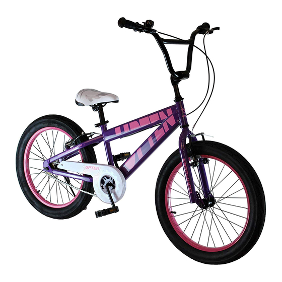
Coaster Bicycles
This manual contains important safety, assembly, operation and
maintenance information.
Please read and fully understand this manual
before operation.
Save this manual for future reference.
See back page for Customer Service Information
Consulte el reverso para Servicio de Información al Cliente
Voir pages verso pour des renseignements le service à la clientèle
Advertisement
Table of Contents

Related Manuals for Huffy Coaster


Summary of Contents for Huffy Coaster
- Page 1 HCoaster 12-20 EN 111616 © Copyright Huffy Corporation 2017 Owner’s Manual Coaster Bicycles This manual contains important safety, assembly, operation and maintenance information. Please read and fully understand this manual before operation. Save this manual for future reference. See back page for Customer Service Information Consulte el reverso para Servicio de Información al Cliente...
-
Page 2: Table Of Contents
• Pedal Installation........................15 • Training Wheel Installation (various models) ............16-17 • Brake System Setup (various models) ............... 18-21 • Brake Pad Replacement ......................21 • Coaster Brake ..........................22 Accessories - various models • Streamers, Handlebar Pad and Bag ................23 • Plaques Installation ......................24 •... -
Page 3: Owner's Bicycle Identification Record
Owner’s Bicycle Identifi cation Record NOTE: This information is only available on the bicycle itself. It is not available from Huff y. Each Huff y bicycle has a Recovery Code stamped into the frame. The Recovery Code can be found on the bottom of the crank ... -
Page 4: Warning And Safety Information
Warning and Safety Information Meanings of Warnings: This symbol is important. See the word “CAUTION” or “WARNING” which follows it. The word “CAUTION” is before mechanical instructions. If you do not obey these instruc- tions, mechanical damage or failure of a part of the bicycle can occur. The word “WARNING”... -
Page 5: Rules Of The Road / Reflectors
Rules of the Road WARNING: Failure of the rider to obey the following “Rules of the Road” can result in injury to the rider or to others. • Obey all traffi c regulations, signs, and signals. • Always wear a bicycle helmet that meets CPSC safety standards, as well as local safety standards. -
Page 6: Parts Assembly View
Parts View... -
Page 7: Parts Assembly List
Parts List... -
Page 8: Introduction To Assembly
Introduction to Assembly This Owner’s Manual is made for several diff erent bicycles: • Some illustrations may vary slightly from the actual product. • Follow instructions completely. • If the bicycle has any parts that are not described in this manual, look for separate “Special Instructions”... -
Page 9: Installing The Front Wheel
Installing the Front Wheel NOTE: See Brake Section to loosen and Re-attach front Brakes (if equipped). 1. If the Axle Nuts are already attached to the front wheel axle, begin by remov- ing them with an open end wrench or adjustable wrench. 2. -
Page 10: Handlebar And Stem Installation
Handlebar and Stem Installation WARNING: To prevent steering sys- tem damage and possible loss of control, the “MIN-IN” (minimum insertion) mark on the stem must be below the top of the Locknut NOTE: • Remove plastic Cap from the end of the Stem •... -
Page 11: Testing Stem And Handlebar Tightness
Handlebar and Stem Installation - continued One Bolt Clamp (fi g C): • If necessary, re-adjust Handlebar for proper fi t. • Tighten Clamp Nut NOTE: Do not over tighten. See torque table for recommended torque. WARNING: If the handlebar clamp in not tight enough, the handlebar can slip in the stem. -
Page 12: Seat Installation (Various Models)
Seat Installation (various models) Seat to Seat Post (Single Bolt Style): Some models are equipped with a seat and seat post assembly that uses a single bolt and nut to secure the seat to the seat post. The seat is as- sembled to the seat post at the factory Ensure the seat is secure to the seat post and the seat bolt is tightened. - Page 13 Seat Installation - continued WARNING: If the clamping force of the Quick Release Lever is too light, the seat post can loosen while riding. This can cause injury to the rider or to others. Tighten the quick release lever (fi g C): 1.
-
Page 14: Testing Seat Clamp And Post Clamp Tightness
Testing Seat Clamp and Post Clamp Tightness To test the tightness of the seat clamp and the post clamp: WARNING: Every time the quick release mechanism is loosened, make sure the red refl ector is correctly positioned. • Try to turn the seat side-to-side and to move the front of the seat up and down. •... -
Page 15: Pedal Installation
Pedal Installation CAUTION: There is a RIGHT pedal marked and a LEFT pedal marked NOTE: A Pedal Wrench is preferred for attaching Ped- als. A thin open-end wrench can also be used. • The pedal marked has right-hand threads. Tighten it in a clockwise direction. •... -
Page 16: Training Wheel Installation (Various Models)
Training Wheel Installation - 12-18” (30-45cm bikes) To attach the Training Wheels to the Frame: Remove outside Axle Nuts from both sides of Axle Put the Alignment Tab , a Training Wheel Leg and an Axle nut on each end of the rear wheel Axle WARNING: Make sure the notched tab of the Alignment Tab is to the rear of the... - Page 17 Training Wheels - continued Adjusting Training Wheel Height: Make sure both Training Wheels are the same distance from the ground (1/8in (3.17mm)) and pointing straight down. Tighten Axle Nuts securely. See torque table for recommended torque. 1/8” 1/8” (3.17mm) OPERATION: WARNING: Before each ride, make sure both axle nuts are tight.
-
Page 18: Brake System Setup (Various Models)
Caliper Rim Brake System Setup (various models) WARNING: You must adjust the front brakes before you ride the bicycle. NOTE: FRONT AND REAR BRAKE SETUP IS THE SAME. Step One: Put the brake shoes in the correct position: • Loosen the Screw of each Brake Shoe •... - Page 19 Caliper Rim Brake System Setup - continued Step 1: • Loosen Cable Nut so that the cable is loose. Step 2: • Insert Cable Barrel into Brake Lever. Step 3: • Insert Brake Cable into Groove as shown. ...
- Page 20 Caliper Rim Brake System Setup - continued Step 5: • Squeeze Brake Arms so that Brake Pads are against the Rim. Step 6: • Pull Brake Cable tight. • Tighten Cable Nut • Adjust Cable Nut for 1/16in (1.5mm) Brake ...
-
Page 21: Brake Pad Replacement
Install new Brake Shoe, making sure it is pointing forward and lined up evenly with the Wheel Rim Tighten brake pad Bolt/Screw accord- ing to Torque Chart. WARNING: Replace Brake Pad with same model and type as original. coaster brakes >>... -
Page 22: Coaster Brake
If your bicycle has a caliper brake(s) in addition to the coaster brake, always use the coaster brake as the main brake to stop the bicycle. WARNING: If you do not... -
Page 23: Streamers, Handlebar Pad And Bag
Streamers, Pad and Bags (various models) NOTE: NOT ALL BIKES HAVE ALL ACCESSORIES! Handlebar Pad: • Remove the cover from the Handlebar pad • Push foam pad over handlebar brace • Wrap handlebar pad cover around foam pad and close with the Hook and Loop strip Streamers: •... -
Page 24: Plaques Installation
Plaques Installation (various models) VIEW 1: Bracket Mount: • Attach Plaque to Handlebar Cross Brace using supplied Clamps and Screws • Tighten Screws so that the Plaque does not move. • Do not over-tighten Screws. This may dam- age the Plaque. VIEW 2: Zip-Tie Mount: •... -
Page 25: Bell And Handlebar Features
• Make sure front Refl ectors are not blocked by Plaque. Bell and Handlebar Features (various models) Bells and Features: • If the mounting Screw is factory in- stalled, remove it and set aside. • Open the Clamp just enough to fi t on the handlebar. -
Page 26: Repair And Service
Repair and Service WARNING: • Inspect the product frequently. Failure to inspect the product and to make repairs or adjustments, as necessary, can result in injury to the rider or to others. Make sure all parts are correctly assembled and adjusted as written in this manual and any “Special Instructions”. -
Page 27: Tires / Tire Pressure Table
Tires Maintenance: • Frequently check the tire infl ation pressure because all tires lose air slowly over time. For extended storage, keep the weight of the off the tires. • Do not use unregulated air hoses to infl ate the tire/tubes. An unregulated hose can sud- denly over infl ate tires and cause them to burst. -
Page 28: Inspection Of The Bearings
WARNINGS: • The chain must remain on the sprock- ets. If the chain comes off the sprock- ets, the coaster brake will not operate. • Do not attempt chain repairs. If there is a problem with the chain, have a bicycle service shop make any repairs. -
Page 29: Lubrication And Lubrication Table
Lubrication WARNING: • Do not over lubricate. If oil gets on the wheel rims or the brake shoes, it will reduce brake performance and a longer distance to stop the bicycle will be necessary. Injury to the rider or to others can occur. •... -
Page 30: Warranty
Limited Warranty General: • Used in a manner contrary to the instructions • Part or model specifi cations are subject to and warnings in this Owner’s Manual change without notice. • This Limited Warranty is the only warranty Huff y will not be liable for incidental or for the product. - Page 31 WARNING: ALWAYS WEAR YOUR HELMET WHEN RIDING THIS PRODUCT! • Helmet should sit level on your head and low on your forehead • Adjust the strap sliders below the ear on both sides. • Buckle the chin strap. Adjust strap until it is snug. •...
- Page 32 ANTES DE DEVOLVER EL RETOURNER AU MAGASIN, PRODUCTO A LA TIENDA, COMMUNIQUEZ AVEC LE SERVICE COMUNÍQUESE CON SERVICIO À LA CLIENTÈLE DE HUFFY. NOUS AL CLIENTE DE HUFFY. NOS VOUS AIDERONS VOLONTIERS AVEC COMPLACE AYUDARLO CON TOUT PROBLÈME CONCERNANT LES CUALQUIER PARTE O PROBLEMA PIÈCES OU LE MONTAGE!
Need help?
Do you have a question about the Coaster and is the answer not in the manual?
Questions and answers