Table of Contents
Advertisement
Quick Links
Advertisement
Table of Contents

Related Manuals for Askey TCG310


Summary of Contents for Askey TCG310
- Page 1 TCG310 USER MANUAL Page 1 / 65...
-
Page 2: Table Of Contents
SAFETY INSTRUCTIONS AND REGULATORY NOTICES ..............5 Chapter 1: Connections and Setup ....................... 10 Cable Modem Overview ............................10 Front Panel ........................10 Rear Panel ........................12 Bottom Side Panel for TEL ....................13 Wall Mounting ........................14 Relationship among the Devices ........................... 15 What the Modem Does ...................... - Page 3 Wi-Fi Web Page Group ............................35 General ........................... 35 WPS ..........................39 MAC Filter ........................40 Reset ..........................41 Settings Web Page Group ............................42 Language ........................42 Password ......................... 43 Configuration ........................44 LAN ..........................45 Internet Time ........................46 LED ..........................
- Page 4 Page 4 / 65...
-
Page 5: Safety Instructions And Regulatory Notices
SAFETY INSTRUCTIONS AND REGULATORY NOTICES Product Safety Notice Before installing or using the product, read these instructions carefully. Be sure to comply strictly precautions. Explanation of risk levels This indication is given where there is an immediate danger of death or serious injury if the person in charge or any third party mishandles the machine or does not avoid the dangerous situation when operating or maintaining the machine. - Page 6 (e.g. airports), you should ask for permission to use the device before turn it on. ASKEY assumes no liability for non-compliance with regulations on the installation site, and radio interference created vis-à-vis third parties and due to non-compliance with national regulations for this application.
- Page 7 power plug of burning or smoke. You should never open the unit yourself because you could be electrocuted. Do not place the product near any source of heat or expose it to direct sunlight. Prohibited Do not expose the product to moisture. Never spill any liquid on the product.
- Page 8 Leave 7cm to 10cm around the appliance to ensure that proper ventilation gets to it. Instruction The screen of the coaxial cable is intended to be connected to earth in the building installation. Be sure to connect the ground wire Do not attempt to disassemble or open covers of this unit by yourself.
- Page 9 Instruction Under normal use condition the user shall keep at least 20cm from the Cable Modem product. Instruction Page 9 / 65...
-
Page 10: Chapter 1: Connections And Setup
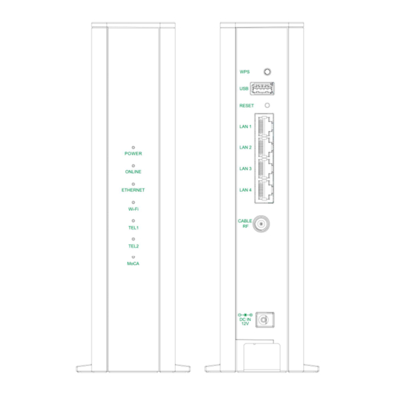
CHAPTER 1: CONNECTIONS AND SETUP Cable Modem Overview Front Panel Fig. 1-1 Front Panel POWER Indicates the power status. Displays the status of your cable connection. The light is off when no cable ONLINE connection is detected and fully lit when the modem has established a connection with the network and data can be transferred. - Page 11 LED from top to bottom. Status Description The device is on. POWER The device boot fail or no power. The device is ready for use. Now you can link to the internet. ONLINE The device is not link to the internet yet or not registration. FLASH The device is in registration process.
-
Page 12: Rear Panel
Rear Panel Fig. 1-2 Rear Panel Slot Description Enables scanning for available WPS client device USB 3.0 host connector (software upgrade only) RESET Reset/Reboot this Cable modem LAN 1 / 2 / 3 / 4 Ethernet 10/100/1000 Base-T RJ-45 connector CABLE RF F-Connector 12VDC... -
Page 13: Bottom Side Panel For Tel
Bottom Side Panel for TEL Fig. 1-3 Bottom Side Panel The TEL 1 / 2 on the Bottom Side panel of TCG310, you can use telephony RJ-11 Connector. Page 13 / 65... -
Page 14: Wall Mounting
Wall Mounting The number of the screw 2 pcs. Direction for wall mounting: Tuner downward or leftward or rightward. Dimension for the screw: diameter: 3.5 mm; length: 30 mm. There are 2 slots on the side of the CABLE MODEM that can be used for wall mounting. Note: When wall mounting the unit. -
Page 15: Relationship Among The Devices
Relationship among the Devices Relationship among the Devices This illustration shows a cable company that offers This illustration shows a cable company that offers DOCSIS/Euro-DOCSIS DOCSIS and PacketCable/Euro-PacketCable compliant voice/data compliant voice/data services. Fig. 1-5 Connection overview What the Modem Does The Wireless Voice Gateway provides high The Wireless Voice Gateway provides high-speed Internet access as well as cost speed Internet access as well as cost-effective, toll-... -
Page 16: Contact Your Local Cable Company
Contact Your Local Cable Company You will need to contact your cable company to establish an Internet account before you can use your gateway. You should have the following information ready (which you will find on the sticker on the gateway): •... -
Page 17: Attaching The Cable Tv Wire To The Wireless Voice Gateway
Attaching the Cable TV Wire to the Wireless Voice Gateway Locate the Cable TV wire. You may find it one of three ways: Connected directly to a TV, a Cable TV converter box, or VCR. The line will be connected to the jack, which should be labeled either IN, CABLE IN, CATV, CATV IN, etc. -
Page 18: Installation Procedure For Connecting To The Ethernet Interface
Installation procedure for connecting to the Ethernet interface Follow these steps for proper installation. (Please refer to Fig. 1-7) Plug the coaxial cable to the cable wall outlet and the other end to the modem’s cable connector. Note: To ensure a fast registration of the modem, the coaxial cable must be connected to the modem before it is powered on. -
Page 19: Telephone Or Fax Connection
Telephone or Fax Connection When properly connected, most telephony devices can be used with the Wireless Voice Gateway just as with a conventional telephone service. To make a normal telephone call, pick up the handset; listen for a dial tone, then dial the desired number. For services such as call waiting, use the hook switch (or FLASH button) to change calls. -
Page 20: Chapter 2: Web Configuration
CHAPTER 2: WEB CONFIGURATION To make sure that you can access the Internet successfully, please check the following first. 1. Make sure the connection (through Ethernet) between the Wireless Voice Gateway and your computer is OK. 2. Make sure the TCP/IP protocol is set properly. 3. - Page 21 If you login successfully, the main page will appear. You can change the display language to “English”, “Suomi”, “中文”, “ Deutsche”, “Nederlands”, “Francais” or “日本語” on the top of the page. Fig. 2-2 Switch Language Page 21 / 65...
-
Page 22: Overview Web Page Group
Overview Web Page Group Overview The Overview page is the start page. You could switch to other page The Overview page is the start page. You could switch to other pages. (e.g., . (e.g., Internet, Wi-Fi, Setting, USB, MoCA, Status) This page display Wi-Fi, ETHERNET and VoIP connection status. -
Page 23: Internet Web Page Group
Internet Web Page Group Advanced This page allows you to enable/disable some advanced features of the Wireless Voice Gateway. Fig.2-4 Internet\Advanced WAN Blocking prevents others on the WAN side from being able to ping your gateway. With WAN Blocking enabled, your gateway will not respond to pings it receives, effectively “hiding”... -
Page 24: Port Mapping
Port Mapping This page allows configuration of This page allows configuration of Port Forwarding and Port Triggering. Fig.2-5 Internet\Port Mapping Port Forwarding For LAN WAN communications, the gateway normally only allows you WAN communications, the gateway normally only allows you to originate an IP connection with a PC on the WAN;... -
Page 25: Parental Control
Parental Control This page allows you to set the time limit for a client’s network usage. Fig.2-6 Internet\Parental Control Page 25 / 65... -
Page 26: Firewall
Firewall This page allows you to enable/disable, and you can choose “Off”, “Low”, “Medium”, “High” firewall protection. The Low setting does not block any services/ports, however it does protect against invalid packets and well known attacks. The Medium setting will cause the firewall to drop a packet unless it is on a specific port of allowed services. -
Page 27: Ip Filtering
IP Filtering This page enables you to enter the IP address ranges of PCs on your LAN that you don’t want to have outbound access to the WAN. These PCs can still communicate with each other on your LAN, but packets they send to WAN addresses are blocked by the gateway. Fig.2-8 Internet\IP Filtering Page 27 / 65... -
Page 28: Dmz Host
DMZ Host Use this page to designate one PC on your LAN that should be left Use this page to designate one PC on your LAN that should be left accessible to all PCs from the accessible to all PCs from the WAN side, for all ports. -
Page 29: Dynamic Dns
Dynamic DNS This page allows to setup for Dynamic DNS server. Fig.2-10 Internet\Dynamic DNS Dynamic DNS- Turn “ON” to enable the dynamic DNS function. Provider- Choose Provider to enable the basic setting. Domain Name- The domain name that you registered with your DDNS provider. Account / Email- The account that is registered with your DDNS provider. -
Page 30: Dns Cache
DNS Cache This page allows configuration static DNS in DNS proxy mode. Enter the domain name in plain format (Ex. mydomain.com) Fig.2-11 Internet\DNS Cache Page 30 / 65... -
Page 31: Upnp
UPnP Enable IGD UPnP to allow any local UPnP control point to perform a variety of actions, include Enable IGD UPnP to allow any local UPnP control point to perform a variety of actions, include Enable IGD UPnP to allow any local UPnP control point to perform a variety of actions, include retrieving the external IP address of the device, enumerate existing port mappings, and add or retrieving the external IP address of the device, enumerate existing port mappings, and add or retrieving the external IP address of the device, enumerate existing port mappings, and add or... -
Page 32: Rip Setup
RIP Setup This page allows configuration of RIP parameters related to authentication, destionation This page allows configuration of RIP parameters related to authentication, destionation This page allows configuration of RIP parameters related to authentication, destionation IP address, and reporting intervals. RIP is used in WAN networks to identify and use the best address, and reporting intervals. -
Page 33: Diagnostic
Diagnostic This page offers basic diagnostic tools for you to This page offers basic diagnostic tools for you to use when connectivity problems occur. When when connectivity problems occur. When you ping an Internet device, you send a packet to its TCP/IP stack, and it sends one back to ping an Internet device, you send a packet to its TCP/IP stack, and it sends one back to ping an Internet device, you send a packet to its TCP/IP stack, and it sends one back to yours. -
Page 34: Mac Base Passthrough
MAC base Passthrough This page allows you configure passthrough CPEs via MAC address. (bypass NAT) Fig.2-15 Internet\MAC base Passthrough Page 34 / 65... -
Page 35: Wi-Fi Web Page Group
Wi-Fi Web Page Group General This page allows configuration of the 2.4GHz and 5GHz wireless features. These must match the settings you make on your wireless-equipped PC on the LAN side. Fig.2-16 Wi-Fi\General Page 35 / 65... - Page 36 2.4GWi-Fi Network / 5GWi-Fi Network: It may help you to Enable or Disable the 2.4GHz / 5GHz wireless function. Current Channel: The channel that you choose will be displayed in this field. Current Bandwidth: The bandwidth that you choose will be displayed in this field. Wi-Fi Name (SSID): The SSID for 2.4GHz / 5GHz wireless function.
- Page 37 Fig.2-17 Wi-Fi\General\QR Code Fig.2-18 Wi-Fi\General\Scanning result WIFI: S (SSID): ASK_P1_XXXX T (Wi-Fi Protection): WPA P (Network key): 1234567890 Page 37 / 65...
- Page 38 802.11x Authentication introduction If you enable the 802.11x authentication function, you will have to offer the following information- WEP-64 (Wired Equivalent Privacy): WEP-64 is a simple security protocol for wireless networks that encrypts transmitted data. The WEP key can be entered as a string of 10 hexadecimal characters (0–9 and A–F).
-
Page 39: Wps
This page allows you to configure WPS setting. Wi-Fi Protected Setup (WPS) is an easy and secure way of configuring and connecting your Wireless access point. In this case, the Wireless Voice Gateway is the Access Point (AP), and your PC (or Wireless Device) is called the STA. When configuring your Wireless Network via WPS, messages are exchanged between the STA and AP in order to configure the security settings on both devices. -
Page 40: Mac Filter
MAC Filter By entering MAC Address, you can configure which local PCs are allowed access to the WAN. Besides the list of MAC filter, any local PCs else would be blocked to the WAN. Fig.2-20 Wi-Fi\MAC Filter Page 40 / 65... -
Page 41: Reset
Reset This page allows configuration of the wireless network to default. Fig.2-21 Wi-Fi\Reset Page 41 / 65... -
Page 42: Settings Web Page Group
Settings Web Page Group Language This page allows configuration of language. You can change the display language to “English”, “Suomi”, “中文”, “ Deutsche”, “Nederlands”, “Francais” or “日本語” on the top of the page. Fig.2-22 Setting\Language Page 42 / 65... -
Page 43: Password
Password user" and password is "user". By default, the username is "user When the current password is the default one, the user is strongly encouraged to change the When the current password is the default one, the user is strongly encouraged to change the When the current password is the default one, the user is strongly encouraged to change the default web password. -
Page 44: Configuration
Configuration This page allows you to save your current settings locally on This page allows you to save your current settings locally on your PC, or restore settings your PC, or restore settings previously saved. Fig.2-24 Setting\Configuration Save & Restore User Configuration Save &... -
Page 45: Lan
This page allows configuration of the basic features of the broadband gateway related to your This page allows configuration of the basic features of the broadband gateway related to your This page allows configuration of the basic features of the broadband gateway related to your ISP’s connection. -
Page 46: Internet Time
Internet Time This page allows configuration and display of the system time obtained from network servers This page allows configuration and display of the system time obtained from network servers This page allows configuration and display of the system time obtained from network servers via Simple Network Time Protocol. -
Page 47: Led
This page allows configuration of the LED brightness. Fig.2-27 Setting\LED Page 47 / 65... -
Page 48: Usb Web Page Group
USB Web Page Group USB Basic This page allows basic control of the USB devices shared over the network. allows basic control of the USB devices shared over the network. allows basic control of the USB devices shared over the network. Fig.2-28 USB\USB Basic Page 48 / 65... -
Page 49: Media Server
Media Server This page controls configuration controls configuration and scanning of the cable modem’s media server. s media server. Fig.2-29 USB\Media Server Page 49 / 65... -
Page 50: Cpus Server
CPUS Server This page allows control of the USB allows control of the USB Printer shared over the network. Fig.2-30 USB\CPUS Server Page 50 / 65... -
Page 51: Moca Web Page Group
MoCA Web Page Group MoCA You will be able to change your MoCA setting here. MoCA is a new technology which utilizes your existing CATV coax at home to form a home networking which will provide high speed home network access. Fig.2-31 MoCA\MoCA Page 51 / 65... -
Page 52: Status Web Page Group
Status Web Page Group Status This page can find an overview of all your router parameters. This may This page can find an overview of all your router parameters. This may help you in optimizing help you in optimizing or trouble shooting your router. Fig.2-32 Status\Status Page 52 / 65... -
Page 53: Voice Status
Voice Status This page displays the initialization status of the MTA containing Telephony DHCP, Security, TFTP and Provisioning Status. The information can be useful to your cable company’s support technician if you’re having problems. Fig.2-33 Status\Voice Status Page 53 / 65... -
Page 54: Upstream
Upstream This page reports current CM’s upstream information containing Transmitter #, Channel ID, Lock Status, Frequency, Symbol Rate, Channel Type and Power. The information can be useful to your cable company’s support technician if you’re having problems. Fig. 2-34 Status\Upstream Page 54 / 65... -
Page 55: Downstream
Downstream This page reports current CM’s downstream information containing Receiver #, Channel ID, Lock Status, Frequency, Modulation, SNR and Power. The information can be useful to your cable company’s support technician if you’re having problems. By entering frequency in KHz and clicking “Force frequency”... -
Page 56: Event Log
Event log This page displays the contents of the SNMP event log. Fig. 2-36 Status\Event log Page 56 / 65... -
Page 57: Spectrum Analyzer
Spectrum Analyzer This function can be accessed via click Spectrum Analyzer on GUI. The username is "admin" and password is "aDm1n$TR8r ". The Spectrum Analyzer software enables the user to configure an interactive GUI to study the RF characteristics on the cable modem. The controls behave normally as they do on a regular spectrum analyzer. -
Page 58: Chapter 3: Additional Information
CHAPTER 3: ADDITIONAL INFORMATION Frequently Asked Questions Q. How do I get the system installed? A. Professional installation from your cable provider is strongly recommended. They will ensure proper cable connection to the modem and your computer. However, your retailer may have offered a self- installation kit, including the necessary software to communicate with your cable ISP. -
Page 59: General Troubleshooting
General Troubleshooting You can correct most problems you have with your product by consulting the troubleshooting list that follows. I can’t access the internet. Check all of the connections to your Cable Modem. Your Ethernet card may not be working. Check each product’s documentation for more information. -
Page 60: Service Information
Service Information If you purchased or leased your Cable Modem directly from your cable company, then warranty service for the Digital Cable Modem may be provided through your cable provider or its authorized representative. For information on 1) Ordering Service, 2) Obtaining Customer Support, or 3) Additional Service Information, please contact your cable company. -
Page 61: Federal Communication Commission Interference Statement
Federal Communication Commission Interference Statement This device complies with Part 15 of the FCC Rules. Operation is subject to the following two conditions: (1) This device may not cause harmful interference, and (2) this device must accept any interference received, including interference that may cause undesired operation. This equipment has been tested and found to comply with the limits for a Class B digital device, pursuant to Part 15 of the FCC Rules. - Page 62 FOR MOBILE DEVICE USAGE (>28cm/low power) Radiation Exposure Statement: This equipment complies with FCC radiation exposure limits set forth for an uncontrolled environment. This equipment should be installed and operated with minimum distance 28cm between the radiator & your body. FOR COUNTRY CODE SELECTION USAGE (WLAN DEVICES) Note: The country code selection is for non-US model only and is not available to all US model.
-
Page 63: Industry Canada Statement
Industry Canada statement: This device complies with ISED’s licence-exempt RSSs. Operation is subject to the following two conditions: (1) This device may not cause harmful interference, and (2) this device must accept any interference received, including interference that may cause undesired operation. Le présent appareil est conforme aux CNR d’... - Page 64 (v) De plus, les utilisateurs devraient aussi être avisés que les utilisateurs de radars de haute puissance sont désignés utilisateurs principaux (c.-à-d., qu’ils ont la priorité) pour les bandes 5250-5350 MHz et 5650-5850 MHz et que ces radars pourraient causer du brouillage et/ou des dommages aux dispositifs LAN-EL.
-
Page 65: Caution For Ul (Check Caution Label On Gift Box)
CAUTION for UL (Check caution label on gift box) North American Cable Installer: This reminder is provided to call your attention to Article 820.93 of the National Electrical Code (Section 54 of the Canadian Electrical Code, Part 1) which provides guidelines for proper grounding and, in particular, specifies that the cable ground shall be connected to the grounding system of the building as close to the point of cable entry as practical.
Need help?
Do you have a question about the TCG310 and is the answer not in the manual?
Questions and answers