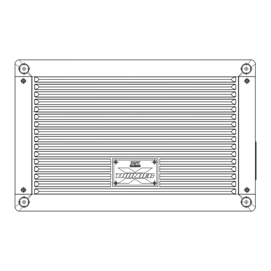
Table of Contents
Advertisement
Quick Links
Advertisement
Table of Contents

Summary of Contents for MTX XTHUNDER125.4
- Page 1 OWNER’S MANUAL XTHUNDER AMPLIFIERS...
-
Page 2: Control Functions
Thank you for purchasing this MTX Audio Hi-Performance amplifier. Proper installation matched with MTX speakers and subwoofers provide superior sound and performance for endless hours of enjoyment whether you are waking the neighbors or just out enjoying your tunes. Congratulations... -
Page 3: Panel Layout
Slave amplifier to the negative speaker input terminal on the subwoofer or terminal cup. Use caution not to connect the negative speaker output terminal on either amplifier to the ground or chassis. PANEL LAYOUT XTHUNDER125.4 4-Channel Amplifier Panel Layout – – R CH +... - Page 4 PANEL LAYOUT XTHUNDER800.5 5-Channel Amplifier Panel Layout – – R CH + +12V L CH FUSE FRONT SPEAKER OUTPUT REAR POWER INPUT – – – R CH + L CH XTHUNDER800.5 BRIDGE FRONT REAR FRONT REAR REMOTE TURN ON LEVEL FREQ LEVEL FREQ...
-
Page 5: Installation And Mounting
(GND) terminal on the MTX amplifier. 6. Connect a Remote Turn-On wire from the source unit to the MTX amplifier’s (REM) terminal. If the source unit does not have a dedicated Remote Turn-On lead, you may connect to the source unit’s Power Antenna lead. -
Page 6: Installation
INSTALLATION For proper perfomance and safety, MTX recommends installing an inline fuse per the owner’s manual instructions according to the following. XTHUNDER1500.1 160A Fuse XTHUNDER1200.1 120A Fuse XTHUNDER800.5 80A Fuse XTHUNDER125.4 80A Fuse TROUBLESHOOTING Problem Cause Solution No +12V at Remote Connection... -
Page 7: Specifications
SPECIFICATIONS Model XTHUNDER1500.1 XTHUNDER1200.1 XTHUNDER800.5 XTHUNDER125.4 1 x 1500 W RMS 1 x 1200 W RMS 1 x 400 W RMS Description 4 x 125 W RMS Mono Mono 4 x 125 W RMS RMS Power at 14.4V 1Ω Load... -
Page 8: Remote Signal
WIRING DIAGRAM Mono Block Amplifier Wiring (Single Subwoofer Load) +12V – FUSE SPEAKER OUTPUT XTHUNDER1500.1 POWER INPUT Remote Signal FUSE Source Unit 1 Ohm Minimum RCA Signal LINE OUT LINE INPUT REMOTE TURN ON INPUT L CH L CH OUTPUT POWER AUTO SLAVE... - Page 9 WIRING DIAGRAM Mono Block Amplifier Wiring (Multi-Subwoofer Load) +12V – FUSE SPEAKER OUTPUT XTHUNDER1500.1 POWER INPUT Remote Signal FUSE Source Unit 2 Ohm Minimum RCA Signal 2 Ohm Minimum LINE OUT LINE INPUT REMOTE TURN ON INPUT L CH L CH OUTPUT POWER AUTO...
- Page 10 WIRING DIAGRAM XTHUNDER125.4 Amplifier Wiring (4-Channel Mode) Crossover Crossover – – +12V L CH R CH + FUSE FRONT SPEAKER OUTPUT REAR POWER INPUT – L CH + – R CH + XTHUNDER125.4 BRIDGE FUSE Crossover Remote Signal Source Unit...
- Page 11 WIRING DIAGRAM XTHUNDER125.4 Amplifier Wiring (3-Channel Mode) Crossover Crossover – – +12V L CH R CH + FUSE FRONT SPEAKER OUTPUT REAR POWER INPUT – L CH + – R CH + XTHUNDER125.4 BRIDGE FUSE Remote Signal Source Unit 4-Ohm to 8-Ohm...
- Page 12 WIRING DIAGRAM XTHUNDER800.5 Amplifier Wiring (5-Channel Mode) Crossover Crossover – – R CH + +12V L CH FUSE FRONT SPEAKER OUTPUT REAR POWER INPUT – – – R CH + L CH XTHUNDER800.5 BRIDGE FUSE Crossover Remote Signal Source Unit Crossover 2 Ohm Minimum RCA Signal...


Need help?
Do you have a question about the XTHUNDER125.4 and is the answer not in the manual?
Questions and answers