jotron Tron AIS TR-8000 Technical Manual
Ais class a transponder
Hide thumbs
Also See for Tron AIS TR-8000:
- Operator and installation manual (104 pages) ,
- Quick reference manual (12 pages) ,
- Operator and installation manual (38 pages)
Table of Contents
Advertisement
Advertisement
Table of Contents

Related Manuals for jotron Tron AIS TR-8000


Summary of Contents for jotron Tron AIS TR-8000
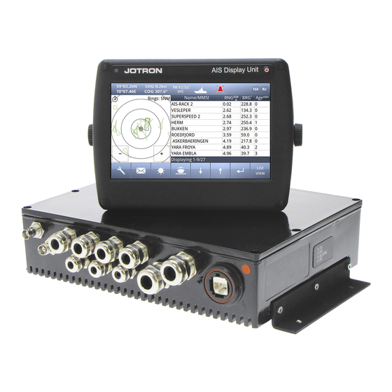
- Page 1 TECHNICAL MANUAL Tron AIS TR-8000 AIS Class A transponder www.jotron.com...
-
Page 2: Table Of Contents
EC Declaration of Conformity, available at www.jotron.com Table of Contents 1 Revision History........................1-4 2 SPECIFICATIONS ........................2-5 Transponder unit ............................2-5 2.1.1 Integrated GPS ................................. 2-5 2.1.2 TDMA Transmitter ..............................2-6 2.1.3 TDMA Receivers ..............................2-6 2.1.4 DSC Receiver ................................2-7 Display unit: .............................. - Page 3 Output................................4-25 4.2.1 ABK - Addressed and binary broadcast acknowledgement ..............4-25 4.2.2 ACA See “Input “ ..............................4-25 4.2.3 ALR - Set alarm state ............................4-25 4.2.4 EPV See “Input “ ..............................4-26 4.2.5 HBT See “Input “ ..............................4-26 4.2.6 LRF ...
-
Page 4: Revision History
Revision History AMENDMENT INCORP. DATE PAGE(S) VERSION REASON FOR CHANGE Added “IEC60945 Protected” 12.4.2012 to chapter 2.2 TR-8000 Technical manual... -
Page 5: Specifications
SPECIFICATIONS Transponder unit Size: 274 x 204 x 67 mm Size with bracket: (319 x 204 x 76 mm) Weight: 3.7 Kg Color: Black Enclosure: Aluminium Supply voltage: 12-24 VDC +30% / -10% Power consumption: <15W average <50W burst Operating temperature: -25°C to +55°C Storage temperature: -40°C to +70°C... -
Page 6: Tdma Transmitter
2.1.2 TDMA Transmitter Frequency Error < +/- 0.5 kHz under normal conditions (n.c.). < +/- 1.0 kHz under extreme conditions (e.c.). Frequency Range 156.025-162.025MHz Channel Switching Time < 25 ms. Carrier Power, High power setting 12.5 W, 41dBm +/- 1.5dB (n.c.) +/- 3.0dB (e.c.) Carrier Power, Low power setting 1 W, 30dBm... -
Page 7: Dsc Receiver
2.1.4 DSC Receiver Frequency Range Ch 70, 156.525 MHz < 20% PER @ –107 dBm (n.c.) Sensitivity < 20% PER @ –101 dBm (e.c.) Modulation PSK, 1200 Baud. < 1% PER @ –7 dBm Error beaviour at high input levels Between –10.0 db and 0 dB.See 61993-2, 5.4.3 Co-Channel Rejection Adjacent Channel Selectivity... -
Page 8: Display Unit
2.2 Display unit: Size: 192 x 144 x 52 mm Size with bracket: (210 x 150 x 84 mm) Weight: 1.0 Kg Color: Black Enclosure: Supply voltage: 12-24 VDC +30% / -10% Power consumption: < 12W nominal < 20W max intensity Operating temperature: -25°C to +55°C Storage temperature:... -
Page 9: Transmission Intervals
Transmission intervals The transmission intervals are normally as described in . Given certain Table 1: Transmission intervals conditions, as in assigned mode, or when other AIS stations are synchronizing to the unit, the transmission rate might be higher, but the absolute highest rate is once every 2 seconds. Ship’s dynamic conditions Nominal reporting interval 3 min... -
Page 10: Interfaces
Interfaces Input sentences Output sentences Sensor 1, 2 and 3: DTM, GBS, GGA, GLL, GNS, HDT*, OSD, RMC, (External GPS, ROT, VBW, VTG, ZDA Gyro and ROT/LOG) External Display, ABM, ACA, ACK, AIR, ABK, ACA, ALR, EPV, Aux Display/ Pilot AIQ, BBM, EPV, HBT, HBT, NAK, TRL, TXT, Port... -
Page 11: Data Transmission
DATA TRANSMISSION Data transmission Data is transmitted in serial asynchronous form in accordance with the standards referenced in 2.1 of IEC 61162-1/2. The first bit is a start bit and is followed by data bits, least-significant- bit first, as illustrated by figure below. The following parameters are used: - baud rate: 4 800 to 38 400... -
Page 12: Rs232 Interface
3.1.1.1 Electrical characteristics RS422 interface. Parameter Test Condition UNIT Voltage at either bus I/O terminal Differential input voltage A with respect to B Ω Differential input resistance w/jumper Ω Wo/jumper 7680 Positive going input threshold voltage = -8mA IT(+) Negative going input threshold voltage = 8mA -200 -115... - Page 13 3.1.2.1 Electrical characteristics RS232 Unit Input Resistance kΩ Input Voltage Range Input Threshold LOW Input Threshold HIGH Ω Output Resistance Output Voltage Swing ±5.0 ±5.4 Output Short-Circuit Current ±32 ±60 3.1.2.2 Display connection The display is interfaced over Ethernet by LAN8187, enabling data from 10 to 100Mbit/s. The circuit is galvanically isolated by a transformer and isolated to ground by 2kV capacitors.
-
Page 14: Description Of Sentence Format
DESCRIPTION OF SENTENCE FORMAT The following provides a summary explanation of the approved sentence structure according to IEC 61162: $aaccc, c---c*hh<CR><LF> ASCII Description "$" Start of sentence: starting delimiter aaccc Address field: alphanumeric characters identifying type of talker, and sentence formatter. The first two characters identify the talker. -
Page 15: Input
Input 4.1.1 ABM - Addressed Binary and safety related Message Support for ITU-R M.1371 messages 6, 12, 25, 26, 70 and 71 Provides an external application with a means to exchange data using the AIS. !--ABM,x,x,x,xxxxxxxxx,x,x.x,s--s,x*hh<CR><LF> Number of fill-bits, 0-5 Encapsulated data ITU-R M.1371 message ID 6, 12, 25, 26, 70, 71 AIS channel for broadcast of the radio message... -
Page 16: Air - Ais Interrogation Request
4.1.4 AIR - AIS Interrogation Request This sentence supports ITU-R M.1371 message 15. It provides an external application with the means to initiate a request for specific ITU-R M.1371 messages from distant mobile or base AIS stations. $--AIR,xxxxxxxxx,x.x,x,x.x,x,xxxxxxxxx,x.x,x*hh<CR><LF> Message sub-section (Reserved for future use) Number of message requested from station-2 MMSI of interrogated station-2 Message sub-section (Reserved for future use) -
Page 17: Dtm Datum Reference
4.1.7 DTM Datum reference Local geodetic datum and datum offsets from a reference datum $--DTM,W84,a,x.x,a,x.x,a, x.x,ccc*hh<CR><LF> Reference datum Altitude offset, (meter) (Not used) Longitude offset, min, E/W (Not used) Lat offset, min, N/S (Not used) Local datum subdivision code (Not used) Local datum must be W84 if valid position shall be accepted on sensor port Note 1: WGS84 = W84 WGS72 = W72... - Page 18 Property Identifier Property Meaning Value range 0-100 Reserved Sensor 1 baud 4800, 9600, 14400, 19200, 38400 Sensor 2 baud 4800, 9600, 14400, 19200, 38400 Sensor 3 baud 4800, 9600, 14400, 19200, 38400 Long Range baud 4800, 9600, 14400, 19200, 38400 DGNSS baud 4800, 9600, 14400, 19200, 38400...
-
Page 19: Gbs - Gnss Satellite Fault Detection
4.1.9 GBS - GNSS satellite fault detection This message is used to support receiver autonomous integrity monitoring (RAIM). Given that a GNSS receiver is tracking enough satellites to perform integrity checks of the positioning quality of the position solution; a message is needed to report the output of this process to other systems to advise the system user. -
Page 20: Gll - Geographic Position - Latitude/Longitude
4.1.11 GLL - Geographic position - latitude/longitude Latitude and longitude of vessel position, time of position fix and status. $--GLL, llll.ll, a, yyyyy.yy, a, hhmmss.ss, A, a *hh<CR><LF> Mode indicator (see Note 1) Status: A = data valid V = data invalid Time of position (UTC) Longitude , E/W Latitude, N/S... -
Page 21: Hdt - Heading True
4.1.14 HDT - Heading true IMO Resolutions A.424 and A.821. Actual vessel heading in degrees true produced by any device or system producing true heading $--HDT, x.x, T*hh<CR><LF> Heading, degrees true 4.1.15 LRF - Long Range Function This sentence is used in both long-range interrogation requests and long-range interrogation replies. $--LRF,x,xxxxxxxxx,c--c,c--c,c--c*hh<CR><LF>... -
Page 22: Osd Own Ship Data
4.1.17 OSD Own ship data IMO Resolution A.477 and MSC 64(67), Annex 1 and Annex 3. Heading, course, speed, set and drift summary. Useful for, but not limited to radar/ARPA applications. OSD gives the movement vector of the ship based on the sensors and parameters in use. $--OSD, x.x,A,x.x, a,x.x,a,x.x,x.x,a*hh<CR><LF>... -
Page 23: Rot - Rate Of Turn
4.1.19 ROT - Rate of turn IMO Resolution A.526. Rate of turn and direction of turn. $--ROT, x.x, A*hh<CR><LF> Status: A = data valid, V = data invalid Rate of turn, °/min, "-" = bow turns to port 4.1.20 SPW - Security password sentence This sentence can be used for authentication. -
Page 24: Vbw - Dual Ground/Water Speed
4.1.22 VBW - Dual ground/water speed Water-referenced and ground-referenced speed data $--VBW, x.x, x.x, A, x.x, x.x, A, x.x, A, x.x, A*hh<CR><LF> Status: stern ground speed, (A = data valid, V = data invalid) (Not used) Stern transverse ground speed, knots (Not used) Status: stern water speed, (A = data valid, V = data invalid) (Not used) Stern transverse water speed, knots (Not used) Status, ground speed, (A = data valid, V = data invalid) -
Page 25: Zda - Time And Date
4.1.25 ZDA – Time and date UTC, day, month, year and local time zone. $--ZDA, hhmmss.ss, xx, xx, xxxx, xx, xx*hh<CR><LF> Local zone minutes (see Note 1), 00 to +59 Local zone hours (see Note 1), 00 h to ±13 h Year (UTC) Month, 01 to 12 (UTC) Day, 01 to 31 (UTC) -
Page 26: Epv See "Input
4.2.4 EPV See “Input “ 4.2.5 HBT See “Input “ 4.2.6 LRF See “Input “ 4.2.7 LR1 - Long-range Reply with destination for function request "A" The LR1-sentence identifies the destination for the reply and contains the information requested by the "A"... -
Page 27: Nak - Negative Acknowledgement
4.2.10 NAK – Negative acknowledgement In general, the NAK sentence is used when a reply to a query sentence cannot be provided, or when a command sentence is not accepted. The NAK sentence reply should be generated within 1 s. $--NAK,cc,ccc,c--c,x.x,c--c*hh<CR><LF>... -
Page 28: Txt - Text Transmission
4.2.12 TXT - Text transmission For the transmission of short text messages. Longer text messages may be transmitted by using multiple sentences. $--TXT,xx,xx,xx,c--c*hh<CR><LF> Text message, ASCII, up to 61 characters Text identifier, 01-99 Message number, 01 to 99 Total number of messages, 01 to 99 4.2.13 VDM - VHF Data-link Message This sentence is used to transfer the entire contents of a received AIS message packet, as defined in ITU-R M.1371 and as received on the VHF Data Link (VDL), using the "6-bit"... -
Page 29: Ver - Version
4.2.15 VER – Version This sentence is used to provide identification and version information about a device. This sentence is produced as reply to a query sentence. $--VER,x,x,aa,c--c,c--c,c--c, c--c,c--c,c--c,x *hh <CR><LF> Sequencial message identifier Hardware revision Software revision Model code (product code) Manufacturer serial number Unique identifier Vendor ID... -
Page 30: Abbreviations And Definitions
Abbreviations and Definitions Acknowledge Automatic Identification System - A shipborne broadcast transponder system in which ships continually transmit their position, course, speed and other data to other nearby ships and shoreline authorities on a common VHF radio channel. AIS-SART Automatic Identification System-Search And Rescue Transponder AtoN Aid to Navigation BAUD... - Page 31 Heading - The direction, in which the vessel is pointed, expressed as angular distance from north clockwise through 360 degrees. HEADING should not be confused with COURSE. The HEADING is constantly changing as the vessel yaws back and forth across the course due to the effects of sea, wind, and steering error.
- Page 32 Range RX is the telegraph and radio abbreviation for “receive” Search And Rescue Signal-to-Noise ratio (SIN). Quantitative relationship between the useful and non-useful part of the received satellite signal. A high SIN indicates a good receiving condition. Speed Over Ground – Speed in relation to the seabed. SOTMA Self Organized Time Division Multiple Access -An access protocol, which allows autonomous operation on a data link while automatically resolving transmission conflicts.
- Page 33 Fax: +47 33 12 67 80 Fax: +47 33 12 67 80 Fax: +47 32 84 55 30 sales@jotron.com sales@jotron.com sales@jotron.com Jotron UK Ltd. Jotron Asia Pte. Ltd. Jotron USA, Inc. Crosland Park 19 Loyang Way 10645 Richmond Avenue Cramlington Changi Logistics Centre...
Need help?
Do you have a question about the Tron AIS TR-8000 and is the answer not in the manual?
Questions and answers