jotron Tron AIS TR-8000 Operator And Installation Manual
Ais class a transponder
Hide thumbs
Also See for Tron AIS TR-8000:
- Operator and installation manual (104 pages) ,
- Technical manual (33 pages) ,
- Quick reference manual (12 pages)
Table of Contents
Advertisement
Quick Links
Advertisement
Table of Contents

Related Manuals for jotron Tron AIS TR-8000


Summary of Contents for jotron Tron AIS TR-8000
-
Page 2: Table Of Contents
Table of Contents 1 Revision History ..................6 2 Software revisions..................7 3 Introduction ....................8 Safety Instructions ....................8 Compass Safe Distance ..................8 Copyright Notice....................8 Disclaimer Notice ....................8 Disposal Instructions ..................... 9 Software and Hardware revisions ................. 9 Ingress protection .................... - Page 3 7.2.5 Indicating ICONS......................23 7.2.6 Ship List .......................... 24 7.2.6.1 Column description ....................... 25 7.2.7 Graphical View ....................... 26 Voyage Settings ....................28 7.3.1 Navigational Status ......................29 7.3.2 Destination ........................30 7.3.3 ETA ..........................31 7.3.4 Persons Aboard (optional) ..................... 31 7.3.5 Cargo Category .......................
- Page 4 8.3.1.2 Label in transponder with connection tables ............... 52 8.3.1.3 Power connection ......................53 8.3.1.4 Sensor connections ....................... 54 8.3.1.5 External display – ECDIS/Radar connections ..............55 8.3.1.6 Pilot / Aux. Display connection ..................56 8.3.1.7 Alarm Connection ......................57 8.3.1.8 Detailed description of connections, fuses, factory reset etc.
- Page 5 10.2.2 VHF link/Long Range ...................... 90 10.2.2.1 Autonomous Long Range .................... 90 10.2.2.2 Polled Long Range ...................... 90 10.2.2.3 Silent mode ......................... 91 10.2.2.4 Display SART in TEST mode ..................91 10.2.2.5 Test Communication ....................92 10.2.3 CPA/TCPA settings......................93 10.2.4 Internal GPS ........................
-
Page 6: Revision History
Revision History Revision Date Page(s) Versions Reason for change Initial 30.1.2012 Transponder Unit: Initial release 1142-01 01.00.05 - 2141 Display Unit: 1125-00 01.00.05 - 2140 Manual: A Manual: B 7.2.2012 6, 8, 53, Typographic 86, 96 errors, missing references, corrected screenshots 2.3.2012 17,37... -
Page 7: Software Revisions
Software revisions The TR-8000 is delivered with SW version according to table below which is filled in by either Jotron, our Distributor, Dealer or Installation company. When SW update is done according to instructions in Jotron TB 01-2012 (Technical Bulletin), an additional line of information will be filled in to reflect the latest change. -
Page 8: Introduction
Jotron AS reserves the right to make changes without further notice to any products or modules described herein to improve reliability, function or design. Jotron AS does not assume any liability arising out of the application or use of the described product TR-8000 Operator and Installation Manual... -
Page 9: Disposal Instructions
Disposal Instructions The TR-8000 Transponder and Display shall be disposed according to local regulations regarding Electronic Waste Recycling in the country the equipment is taken ashore. At time of writing this manual (2012), there are some common regulations which allies: Europe: Directive 2002/96/EC (WEEE) Waste Electrical and Equipment Directive Equipment is labeled with this symbol:... -
Page 10: Operation General Introduction
Thank you for purchasing this Jotron AIS Class A transceiver. The Jotron TR-8000 has been developed to offer you the highest level of performance and durability and we hope that it will provide many years of reliable service. This product has been designed to meet the highest possible quality standards and should you encounter any problems with this product, please contact your local dealer who will be pleased to offer any assistance. -
Page 11: Equipment List
Type 82484 VHF Antenna Procom CXL 2-1LW/h 84401 GPS/VHF combined antenna AC Marine AIS/GPS-B 81768 Jotron Signal Splitter 86870 Pilot cable for TR-8000 display Jotron 80665 AC/DC Power 100-240 VAC/ 24V DC Jotron 92375 240V AC cable, Europe (for 80665) -
Page 12: Tr-8000 Description
TR-8000 Description The Tron AIS TR-8000 consists of two separate units interconnected by Ethernet. The Transponder is the main unit, handling the basic AIS functionality, including sensors and RF functions, while the Display unit is used for setup and display of the AIS data. -
Page 13: Functionality
Functionality The main features are: Safety of navigation by automatically exchanging navigational data between ships (Class A transponders), coast stations, Class B transponders and receiving positional data from AIS-SARTs (Search and Rescue beacons) and AtoNs (Aids to Navigation). Class A AIS transmitter and receiver (transponder) Class B compatible... -
Page 14: Transponder Unit
Transponder Unit The Transponder Unit contains all the core functionality of the AIS system and can function as a separate unit connected to other display solutions confirming with the Front View AIS message format. It consists of a splash proof Alumina casing with the following connection possibilities: VHF antenna and GPS... -
Page 15: Led Indicators
6.2.1 LED Indicators: Transmission Reception Alarm Status 6.2.2 Main functionality: Transmit and receive AIS data packets over the VHF link Receive DSC messages Provide time and position data from internal GPS Receive and handle data from external sensors. Provide information about own and other ships positions to the display units, both the TR-8000 Display unit, and to high speed ports like “External Display”... -
Page 16: External Display (Ethernet) Connector
6.2.5 External Display (Ethernet) Connector RJ45 type waterproof Ethernet connection For more information see section 8.3.1.5 6.2.6 Multipurpose Cable Glands The Transponder Unit is fitted with up to 9 multipurpose cable glands for waterproof, shielded connection with the unit. There are 3 different sizes in order for the best possible fit for... -
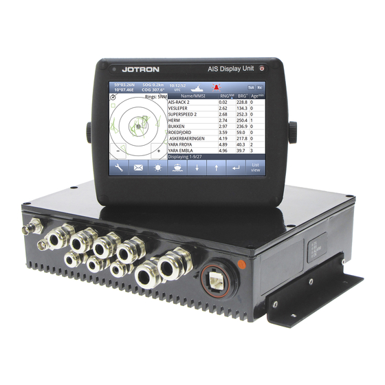
Page 17: Display Unit
Display Unit Front View The Display unit is the user interface for the AIS system on the bridge. It is used to configure the TR-8000 system and to present AIS data about own and other ships, both graphically and in list form. The Display Unit consists of a splash proof housing with a 7 inch LCD colour display with touch screen. -
Page 18: Operational Description
Operational description The operational description chapter assumes that the TR-8000 Ais Transponder is fully installed using the instructions found in the Installation chapter. On/Off button ON/OFF button handles 3 different options When ON/OFF is pushed, a popup menu is displayed with some display Options. Additionally, if the brightness is low, it will automatically be increased. -
Page 19: Power Off Display
7.1.2 Power off Display If the Power off Display is selected, only the Display Unit is turned OFF and the AIS functionality of the Transponder will still be active. Note that the ship list will need some time to recover when turning the Display unit on again. -
Page 20: Display Unit Menu System
Display Unit menu system. Status Bar Content Section Button Bar The main window contains three main sections. 7.2.1 Status Bar Clock Dynamic navigational data Other informative icons Position, Speed, Heading etc Tx,Rx, Nav status, Alarms etc. The Status bar is visible in all the sub menus. TR-8000 Operator and Installation Manual... -
Page 21: Content Section
7.2.2 Content Section Displays the current selected window and the corresponding data Example below shows Main View: Main View is a combination of Graphical and List view: North Graphical List Press column to Sort Head Rings AToN Base Station AIS-SART Own Ship SAR Aircraft Selected... -
Page 22: Important Buttons Shown In Different Views
7.2.4 Important Buttons shown in different Views: Return to last menu without saving. Confirm, save data and return to last menu. If the Icon is not highlighted, indicates no data has changed The Home button will take you to Main view without saving. Enter –... -
Page 23: Indicating Icons
7.2.5 Indicating ICONS Receive data on either of the two AIS channels. If Inactive, shown as Transmit on either channel A or B shown as TxA or TxB. Icon shown is Inactive. Active is shown with Green color as the Rx icon above. Alarm Status: No alarms Alarm caused by one or more incidents from Table 3... -
Page 24: Ship List
7.2.6 Ship List The display unit receives data about all the ships with an active AIS transmitter in the area and presents this data in a list in the main window. The list displays the name or MMSI, range to own ship, bearing and age of presented data. -
Page 25: Column Description
7.2.6.1 Column description Name/MMSI : Shows the MMSI (Maritime Mobile Service Identity) of the ship until its Name is received. Name is transmitted more seldom than MMSI numbers Is the Range to the Vessel in Nautical Miles (NM) BRG°: Bearing to the Vessel in degrees from your position Speed Over Ground in Knots COG°: Course Over Ground in degrees... -
Page 26: Graphical View
7.2.7 Graphical View The graphical display of the ship list plots the positions of other AIS targets relative to your own position in a frame on the left side. A vessel with neither a reported heading nor COG will be oriented toward the top of display area. The user is able to switch between North Up and Head Up, but if no heading or COG is available, or if the ship is anchored/moored, the North Up configuration will automatically be chosen. - Page 27 Different types of targets are displayed with different icons. Active Vessel If the CPA/TCPA system is activated, ships on collision course are displayed with a red color and double thickness of the lines. Own ship is indicated in the same way as other ships, but is always in center. Sleeping target Smaller symbol than “Active Vessel”...
-
Page 28: Voyage Settings
Voyage Settings Red square shows button selected to get to this menu The Voyage Settings contains all the ship data to be entered or changed before or on each voyage. In order for the AIS system to function correctly, it is important to keep these parameters up to date. You may use one of these buttons: Navigational Status Destination... -
Page 29: Navigational Status
7.3.1 Navigational Status The options available for the navigational status are as follows. Under way using engine, At anchor, Not under command Restricted manoeuvrability Constrained by her draught Moored, Aground, Engaged in fishing Under way sailing Not Defined (Default) Vessel not under command means a vessel which through some exceptional circumstance is unable to maneuver as required by these Rules and is therefore unable to keep out of the way of another vessel. -
Page 30: Destination
7.3.2 Destination The destination of the voyage is to be entered here using a maximum of 20 characters. NOTE! Many countries require destination input is according to GUIDANCE ON THE USE OF THE UN/LOCODE IN THE DESTINATION FIELD IN AIS MESSAGES from IMO SN/Circ.244 Text from the Guidance:... -
Page 31: Eta
7.3.3 ETA The Estimated Time of Arrival is displayed to other AIS units and should be updated if the expected arrival time is changed. 7.3.4 Persons Aboard (optional) This parameter indicates the number of persons aboard the ship at the given moment. This parameter is not sent to other ships or base stations, only through the Long Range Port which is... -
Page 32: Draught
7.3.6 Draught The Draught parameter specifies the maximum depth of the ship in meters and decimeters. TR-8000 Operator and Installation Manual... -
Page 33: Messages
Messages WARNING! Use of AIS text messages between ships must not be used to avoid collisions when time is critical. AIS systems are not required to have an audible alarm to indicate the arrival of all text messages. The use of AIS text messaging does not relieve the vessel of other requirements, such as the Vessel Bridge-to-Bridge Radiotelephone regulations or of the requirements to sound whistle signals and display lights or shapes in accordance with the International or Inland Navigation Rules. -
Page 34: Popup When Received Message
7.4.2 Popup when received message Example showing “Popup” of received “Safety message” from AIS SART The message must be acknowledged by pressing “Close” button 7.4.3 Sent messages By pushing the buttons on the bottom bar, you can switch to: Received messages Write New Resend Scroll up or down through... -
Page 35: Write New Message
7.4.4 Write New message Be advised, all messages in this context are SAFETY RELATED and should not be used for other purposes. For this reason, this functionality is protected by a user password. Default Password = OP Select here message recipients: From list (Of received ships) Enter MMSI (directly) Broadcast (to all) -
Page 36: Message Recipients "From List
7.4.4.1 Message recipients “From list” Select 1. Which ship 2. Confirm with Then a new window opens: 7.4.4.1.1 Write text When a target is selected, the keyboard window opens, and allows the user to write a message. The total allowed length is 156 characters. -
Page 37: Message Recipients "Enter Mmsi
7.4.4.2 Message recipients “Enter MMSI” 1. Enter MMSI 2. Confirm with 3. Write Text (as described above) 4. Select Channel and Send (-“”-) 7.4.4.3 Message recipients “Broadcast” 1. Write Text (as described above) 2. Select Channel and Send TR-8000 Operator and Installation Manual... -
Page 38: Display Settings
Display Settings Red square shows button selected to obtain to this menu In the Display settings menu, you can adjust Brightness level and switch between night and day mode. Each mode has its own brightnesslevel. In the low brightness end of the scale, the steps are more accurate to adapt to very low intensity levels. Touching the empty area at the left or right side of the display restores a 50% brightness level if the display...
Need help?
Do you have a question about the Tron AIS TR-8000 and is the answer not in the manual?
Questions and answers
I need get data from rs232 and feed it to our Qinsy. Found tx rx and gnd from rs232. But i did get the data. I should choose tx and ground to get the data right. The rx and ground to Qinsy.