Table of Contents
Advertisement
Quick Links
Advertisement
Table of Contents

Related Manuals for TECSYSTEM VRT600 SERIES


Summary of Contents for TECSYSTEM VRT600 SERIES
- Page 1 INSTRUCTION MANUAL VRT600 SERIES 1MN0050 REV. 0 operates with ISO9001:2008 certified quality system TECSYSTEM S.r.l. 20094 Corsico (MI) Tel.: +39-024581861 Fax: +39-0248600783 http://www.tecsystem.it R. 1.0 16/09/13 ENGLISH “Translations of the original instructions” ...
-
Page 2: Table Of Contents
INTRODUCTION First of all we wish to thank you for choosing to use a TECSYSTEM product and recommend you read this instruction manual carefully: You will understand the use of the equipment and therefore be able to take advantage of all its functions. -
Page 3: Safety Requirements
POWER SUPPLY The VRT600 series can be supplied by 230Vac 50/60Hz o a 12Vac –Vcc, depending on the model purchased. Before using it, make sure the power cable is not damaged, kinked or pinched. Do not tamper with the power cable. Never disconnect the unit by pulling the cable, avoid touching the pins. -
Page 4: Accessories
* The above terminals are optional according to the configuration purchased. ATTENTION: always install the device using the terminals included in the pack. The use of terminals other than those included with the control unit might cause malfunctions. VRT600 SERIES ... -
Page 5: Technical Specifications
Hole 92 x 92 mm Hole 92 x 92 mm TEST AND PERFORMANCE Construction in compliance with CE regulations ● ● Protection from electrical interference EN 61000-4-4 ● ● VRT600 SERIES ... - Page 6 VRT600 SERIES VRT600 U SERIES TECHNICAL SPECIFICATIONS TEST AND PERFORMANCE Dielectric strength 1500 Vac for 1 minute: supply - relay fault, supply - remote. ● ● Ambient operating temperature from –20°C to +60°C ...
-
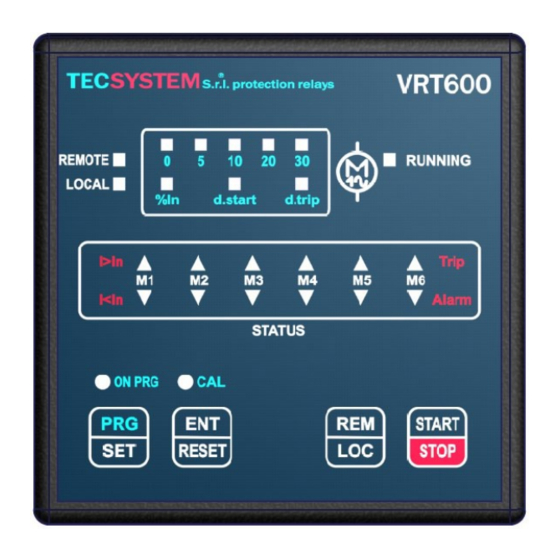
Page 7: Front Panel
Fans' control mode REM/LOC button Monitoring delay LED (yellow) at start up (REMOTE or LOCAL) start d. ENT/RESET button: alarm reset and Release delay LED (yellow) trip d. programming data selection Motors' auto-tuning phase LED (yellow) VRT600 SERIES ... -
Page 8: Installation
Drill a 92 x 92 mm hole in the panel sheet. 1MN0063 REV. 0 Control unit Panel hole dimensions (+0.8mm tolerance) Identification label Fix the unit securely with the blocks supplied. 1MN0008 REV. 0 Control unit Fixing screw Fixing block Crosshead screwdriver #1X100mm VRT600 SERIES ... -
Page 9: Electrical Connections
ELECTRICAL CONNECTIONS VRT600 SERIES 1MN0050 REV. 0 M4-M5-M6 motor line connection M1-M2-M3 motor line connection (5A max) (5A max) M4-M5-M6 fan line supply 230Vac ±10% Remote enabling contact ENABLE 15 amp.max 50-60Hz. Control unit supply FAULT relay (fault signal) 230 Vac ±10% 50-60 Hz 7.5 VA ... -
Page 10: Vrt600 U Back
M1-M2-M3 fan line supply 230Vac ±10% 15 amp.max 50-60Hz. Note: with the power to the unit ON, the FAULT relay switches, contacts 8-9 open (NO) and 7-9 closed (NC). FAULT 8-9 NC: ALARM FAULT OR POWER OFF FAULT 7-9: NC POWER ON VRT600 SERIES... -
Page 11: Power Supply
IMPORTANT NOTE: if an existing control unit must be replaced with a new one, to guarantee its correct and safe operation, all the connecting terminals must be replaced with the new terminals supplied, on condition the brand of the new terminals is different from the one of the previously installed ones. VRT600 SERIES... -
Page 12: Programming
ATTENTION: We recommend you check the control unit before starting the device. The default parameters set by TECSYSTEM might not suit your requirements. Programming the device is the end user’s responsibility: the set alarm thresholds and the enabled functions described in this manual must be checked (by a specialized technician) referring them to the application and system characteristics on which the control unit is installed. -
Page 13: Warranty Regulations
Returning used electrical devices: contact TECSYSTEM or the TECSYSTEM agent for information on the correct disposal of the devices. TECSYSTEM is aware of the impact its products have on the environment and asks its customers active support in the correct and environmentally-friendly disposal of its devices. -
Page 14: Useful Contacts
USEFUL CONTACTS TECHNICAL INFORMATION: ufficiotecnico@tecsystem.it COMMERCIAL INFORMATION: info@tecsystem.it PRODUCT INFORMATION (CATALOGUES) DOWNLOAD CONTROL UNIT MANUALS ACCESSORIES VRT600 SERIES...
Need help?
Do you have a question about the VRT600 SERIES and is the answer not in the manual?
Questions and answers