Table of Contents
Advertisement
Instructions for Installation, Operation and Maintenance of
Magnum DS, DSX and DSL Low Voltage Power Circuit Breakers
I.B. 2C12060H08 Supersedes I.B. 2C12060H07 dated April 2005
Effective May 2006
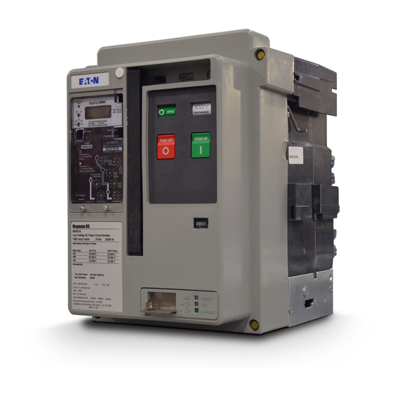
Double-wide Fixed
Narrow Frame Fixed
Standard Frame Fixed
IB2C12060H08
For more information visit: www.EatonElectrical.com
Advertisement
Table of Contents

Subscribe to Our Youtube Channel
Related Manuals for Eaton MDN-408


Summary of Contents for Eaton MDN-408
- Page 1 Instructions for Installation, Operation and Maintenance of Magnum DS, DSX and DSL Low Voltage Power Circuit Breakers I.B. 2C12060H08 Supersedes I.B. 2C12060H07 dated April 2005 Effective May 2006 Double-wide Fixed Narrow Frame Fixed Standard Frame Fixed IB2C12060H08 For more information visit: www.EatonElectrical.com...
- Page 3 Instruction Book Effective: May 2006 Page iii For application information, consult Cutler-Hammer or PURPOSE see applicable Product Guides, Technical Documents, Application Publications and/or Industry Standards. This instruction manual is expressly intended to cover the installation, operation and maintenance of Magnum DS (MDS), DSX (MDSX) and Magnum DSL (MDSL) SAFETY Power Circuit Breakers.
-
Page 4: Table Of Contents
Instruction Book Page iv Effective: May 2006 TABLE OF CONTENTS SECTION 1: INTRODUCTION PAGE General Information.............................1 Safety Features ..............................2 Safety Practices ..............................2 Qualified Personnel .............................3 Other Publications and Documentation.......................3 SECTION 2: RECEIVING, HANDLING AND INSTALLATION General Information.............................4 Suggested Tools ..............................4 Unpacking Circuit Breaker...........................4 2-3.1 Storing Circuit Breaker ...........................4... - Page 5 Instruction Book Effective: May 2006 Page v PAGE Accessory Devices ............................46 3-8.1 Plug-In Electrical Accessories ......................46 3-8.2 Internal Electrical Accessories ......................48 3-8.3 Mechanical Accessories........................50 MDSL Limiters/Blown Limiter Indication......................53 3-9.1 MDSL Current Limiters .........................53 3-9.2 Blown Limiter Sensing..........................53 SECTION 4: DRAWOUT CIRCUIT BREAKER AND CASSETTE General ................................55 4-1.1 Drawout Cassette..........................55...
- Page 6 Instruction Book Page vi Effective: May 2006 FIGURES Figure Title Page Magnum DS Family of Low Voltage Power Fixed and Drawout Circuit Breakers (800-5000 Amperes) ..1 Typical Magnum Nameplate ........................2 1-3 & 1-4 Sample Designation Examples ........................3 Typical Magnum DSL (MDSL) Drawout Breaker with Integral Current Limiters ........3 Shipping Clamps for Drawout Circuit Breaker ..................4 Magnum DS Circuit Breaker with Lifting Yoke Attached ................5 Rear View Showing Current Sensor Rating Through Viewing Window ............6...
- Page 7 Instruction Book Effective: May 2006 Page vii Figure Title Page 3-39 Shunt Trip, Spring Release and Undervoltage Release Installed............47 3-40 Auxiliary Switch (2A/2B)...........................48 3-41 Mechanical Trip Indicator with Associated Overcurrent Trip Switch ............48 3-42 Motor Operator Kit ...........................49 3-43 Motor Operator Installed in Narrow Frame Circuit Breaker..............49 3-44 Cover Mounted Key Lock and Operations Counter.................
- Page 8 Instruction Book Page viii Effective: May 2006 TABLES Table Title Page Magnum DS Ratings at 240, 480, 600 volts ....................2 Magnum DSL Ratings at 600 volts ......................3 Circuit Breaker Weights ..........................5 Rejection Interlock Pin Locations.......................7 Magnum Digitrip Trip Units ........................20 Magnum DS Current Sensors and Matching Rating Plugs..............22 Shunt Trip Ratings ...........................46 Spring Release Ratings ...........................47...
-
Page 9: Section 1: Introduction Page
Instruction Book Effective: May 2006 Page 1 SECTION 1: INTRODUCTION acteristics and arc tracking resistance. MDS, MDSX and MDSL drawout circuit breakers are a 1-1 GENERAL INFORMATION through-the-door design having three breaker positions with the compartment door closed (CONNECT, TEST, The Magnum DS and DSX Power Circuit Breakers can DISCONNECT) and one position out of its compartment be fixed or drawout air circuit breakers utilizing an elec-... -
Page 10: Safety Features
Table 1.1 Magnum DS/DSX Ratings at 240, 480, 600 volts Maximum Breaker Interrupting Short Time Amperes Designation Rating Rating MDN-408 42 kA 42 kA MDN-508 50 kA 50 kA MDN-608 65 kA 65 kA MDS-X08 200 kA (240v, 480v.) -
Page 11: Qualified Personnel
Instruction Book Effective: May 2006 Page 3 1. Only qualified electrical personnel familiar with the M D S C 3 2 equipment, its operation and the associated hazards should be permitted to work on the equipment. Additionally, only qualified personnel should be per- Circuit Breaker Interrupting Frame... -
Page 12: Section 2: Receiving, Handling And Installation
Instruction Book Page 4 Effective: May 2006 SECTION 2: RECEIVING, HANDLING AND On drawout circuit breakers shipped without a cassette, two shipping clamps hook into the breaker side plates INSTALLATION and are held to the pallet with 4 lag screws (Figure 2-1). Remove the lag screws and clamps. -
Page 13: Lifting Circuit Breaker
If the circuit breaker is to be lifted onto compartment extension rails, follow the instructions in paragraph 2-6 entitled “Installing Drawout Circuit Breaker.” Table 2.1 Basic Circuit Breaker Weights Breaker Weights (lbs) Model Fixed Drawout Universal Cassette MDN-408 MDN-508 MDN-608 MDN-412 MDN-512 MDN-612 MDN-416 MDN-516 MDN-616 MDS-408... -
Page 14: Circuit Breaker Inspection
Instruction Book Page 6 Effective: May 2006 2-5 CIRCUIT BREAKER INSPECTION NOT PROPERLY SEATED ON THE EXTENSION RAILS, IT COULD FALL FROM THE RAILS CAUSING EQUIPMENT DAMAGE AND/OR BODILY INJURY. All circuit breakers, once removed from their shipping containers, should be visually inspected for any obvious Carefully lower the circuit breaker down onto the exten- damage. -
Page 15: 2-6.2 Circuit Breaker Positioning
Page 7 Table 2.2 Rejection Interlock Pin Locations Pin Locations CAUTION Cell For: MDN-408, 412, 416 DO NOT DISABLE REJECTION INTERLOCKS. MDN-508, 512, 516 DOING SO AND USING A LOWER CAPACITY CIR- MDN-608, 612, 616 CUIT BREAKER IN AN INCOMPATIBLE CASSETTE... - Page 16 Instruction Book Page 8 Effective: May 2006 Secondary Compartment Connection Not Made Rear of Front Door Compartment Circuit Primary Breaker Connections Side View Not Made Circuit Breaker ■ No Electrical Connections Made Out of Compartment ■ Breaker On Extension Rails On Extension Rails ■...
-
Page 17: 2-6.3 Levering Circuit Breaker
Instruction Book Effective: May 2006 Page 9 Secondary Connection Made Rear of Compartment Compartment Front Door Circuit Primary Breaker Connections Side View Made ■ Full Breaker Operation ■ Primary, Secondary and Ground Connections Made ■ Fully Racked into Cassette (Compartment) Figure 2-9 Connect Position 2-6.3 LEVERING CIRCUIT BREAKER CAUTION... -
Page 18: Fixed Circuit Breaker
Instruction Book Page 10 Effective: May 2006 CONNECT CONNECT TEST TEST DISCONNECT DISCONNECT Figure 2-11 Levering Position Indication Mounting Foot NOTICE Figure 2-12 Typical Fixed Magnum DS Circuit Breaker able for making vertical primary bus connections. The circuit breaker mechanism is interlocked such Secondary connections can be made through standard that charged closing springs are automatically dis- terminal blocks or a special connector compatible with... -
Page 19: Section 3: Circuit Breaker Description And Operation
Instruction Book Page 11 Effective: May 2006 SECTION 3: CIRCUIT BREAKER six (or eight) sets of rear primary connections; these cir- cuit breakers are available from the factory with several DESCRIPTION AND OPERATION different phase sequences, distinguishable by the sixth character in the model number. - Page 20 Instruction Book Page 12 Effective: May 2006 Fixed Horizontal Primary Terminal Fixed Primary Terminal (with optional Vertical Adapter) Arc Chamber Sensor Rating Viewing Window Mounting Foot Baffled Arc Chute Cover Secondary Disconnect Faceplate (Front Cover) Integral Lifting Handle Figure 3-2 Typical MDS/MDSX Fixed Circuit Breaker Features (Front and Rear Views) (MDSX shown without required arc hood) Arc Chamber Integral Current Limiter...
- Page 21 Instruction Book Page 13 Effective: May 2006 Fixed Vertical Primary Terminals Baffled Arc Chute Cover with Optional Vertical Adaptor Secondary Contact Connector Arc Chamber Faceplate (Front Cover) Mounting Foot Integral Lifting Handle Circuit Breaker Nameplate Phase Identification Labels Figure 3-4 Typical Double-wide MDS/MDSX Standard Frame Fixed Circuit Breaker Features (Front and Rear Views) (MDSX shown without required arc hood) For more information visit: www.EatonElectrical.com I .B.
- Page 22 Instruction Book Page 14 Effective: May 2006 CLOSED (Red) (Green) OPEN (Yellow) CHARGED (White) DISCHARGED PUSH ON (Green) PUSH OFF (Red) CONNECT CONNECT TEST TEST DISCONNECT DISCONNECT Red = Connect Yellow = Test Green = Disconnect Manual “OFF” Button (Push) Color Coded-Breaker Trip Flag (Pop Out Indicator) Position Indicator...
-
Page 23: 3-1.1 Mdsl Application/Operation
Instruction Book Page 15 Effective: May 2006 3-1.1 MDSL APPLICATION/OPERATION 3-2 BASIC CIRCUIT BREAKER ASSEMBLY MDSL circuit breakers are intended for applications All Magnum circuit breakers use a rigid frame housing requiring the overload protection and switching functions construction of engineered thermoset composite resins. of air circuit breakers on systems whose available fault This construction provides high strength structural prop- currents (1) exceed the interrupting ratings of the circuit... -
Page 24: 3-3.1 Primary Moving Contacts
Instruction Book Page 16 Effective: May 2006 “Toe” (Arcing Contact) “Heel” (Main Contact) “Toe” (Arcing Contact) “Heel” (Main Contact) Figure 3-9 Standard Frame DS (12-finger) Moving Conductor Assembly Figure 3-8 Narrow Frame (8-finger) Moving Conductor Assembly 3-3.1 PRIMARY MOVING CONTACTS Depending upon the frame size, each primary moving contact assembly is comprised of multiple individual copper contact fingers connected to the load conductor... -
Page 25: 3-3.2 Primary Stationary Contacts
Instruction Book Page 17 Effective: May 2006 3-3.2 PRIMARY STATIONARY CONTACTS complete the manual charging process. It is possible to manually recharge the spring immediately after closing The primary stationary contact is a combination of two the circuit breaker and before it has been tripped open. items (Figure 3-10). -
Page 26: 3-4.2 Electrical Operation
Instruction Book Page 18 Effective: May 2006 Electrical Motor Operator Figure 3-12 Circuit Breaker Closing Springs Being Figure 3-13 Electrical Motor Operator to Charge Manually Charged Closing Spring 3-4.2 ELECTRICAL OPERATION closing, a Latch Check Switch (LCS) option is available (see paragraph 3-8.1) which will block the application of For electrically operated circuit breakers, the springs are the electrical close command until the breaker is ready... - Page 27 Instruction Book Page 19 Effective: May 2006 Arc chute components are assembled in an insulating jacket which is removable from the top of the circuit breaker, as previously described in paragraph 2-4. Each arc chute has a baffled top cover. Top Arc Plate Integral...
-
Page 28: Electronic Tripping System
Instruction Book Page 20 Effective: May 2006 3-6 ELECTRONIC TRIPPING SYSTEM Cutler-Hammer Rating Plug The Magnum DS/DSX/DSL circuit breakers utilize a three part tripping system (Figure 3-17): Trip Trip Unit • Microprocessor-based trip unit Toroidal Actuator • Current Sensors Current •... -
Page 29: Rating Plug
Instruction Book Page 21 Effective: May 2006 3-6.2 RATING PLUG Pop Out Pop Out Trip Flag Trip Flag All Magnum DS/DSX/DSL circuit breaker trip units use a fixed type rating plug. The current rating of the rating plug must match the current rating of the integrally Auxiliary Power Auxiliary Power mounted current sensors (Figure 2-3, 3-18 and Table... -
Page 30: 3-6.4 Trip Actuator
Instruction Book Page 22 Effective: May 2006 trip unit on the breaker’s front faceplate (Figure 3-18). It operates by releasing and popping out any time the cir- cuit breaker trips due to to an overcurrent condition. Note that the mechanical trip indicator will not prevent the breaker from being reclosed. -
Page 31: 3-6.8 Voltage Taps
Instruction Book Page 23 Effective: May 2006 (Figure 3-22). The wiring points are finger safe with 3-6.8 VOLTAGE TAPS no more than two wires per terminal. On circuit breakers with Digitrip 1150 trip units potential taps are required to monitor the three phase voltages. Up to two secondary contact plug-in connectors (AMP), each with 30 secondary points, are mounted on the top Voltage taps may be placed on either the line (top) or... -
Page 32: 3-7.1 Connection Diagrams
Instruction Book Page 24 Effective: May 2006 Drawout type circuit breakers: Compatible secondary Closed Hinged Covers Terminal Blocks plug-in connectors are mounted on the top front portion with Testing Holes of the drawout cassette (Figure 3-24). These connec- tors match and plug into the circuit breaker mounted connectors. - Page 33 Instruction Book Page 25 Effective: May 2006 Figure 3-26 Connection Diagram for Narrow and Standard Frame with Digitrip 520 and 520M (except Narrow 100kA ratings) I.B. 2C12060H08 For more information visit: www.EatonElectrical.com...
- Page 34 Instruction Book Page 26 Effective: May 2006 Figure 3-27 Connection Diagram for Narrow and Standard Frame with Digitrip 520MC (except Narrow 100kA ratings) For more information visit: www.EatonElectrical.com I.B. 2C12060H08...
- Page 35 Instruction Book Effective: May 2006 Page 27 Figure 3-28 Connection Diagram for Narrow 100kA Rating Frame with Digitrip 520 and 520M I.B. 2C12060H08 For more information visit: www.EatonElectrical.com...
- Page 36 Instruction Book Page 28 Effective: May 2006 Figure 3-29 Connection Diagram for Narrow 100kA Rating Frame with Digitrip 520MC For more information visit: www.EatonElectrical.com I.B. 2C12060H08...
- Page 37 Instruction Book Effective: May 2006 Page 29 Figure 3-30 Connection Diagram for Standard and Narrow (except 100kA ratings) Frame with Digitrip 1150 I.B. 2C12060H08 For more information visit: www.EatonElectrical.com...
- Page 38 Instruction Book Page 30 Effective: May 2006 Figure 3-31 Connection Diagram for Narrow Frame (100kA rating) with Digitrip 1150 For more information visit: www.EatonElectrical.com I.B. 2C12060H08...
- Page 39 Instruction Book Page 31 Effective: May 2006 Figure 3-32 Connection Diagram for Double-wide Frame (except MDSX) with Digitrip 520 and 520M with ABCABC Configuration I.B. 2C12060H08 For more information visit: www.EatonElectrical.com...
- Page 40 Instruction Book Page 32 Effective: May 2006 Figure 3-33 Connection Diagram for Double-wide Frame (except MDSX) with Digitrip 520MC with ABCABC Configuration For more information visit: www.EatonElectrical.com I.B. 2C12060H08...
- Page 41 Instruction Book Effective: May 2006 Page 33 Figure 3-34 Connection Diagram for Double-wide Frame (except MDSX) with Digitrip 1150 with ABCABC Configuration I.B. 2C12060H08 For more information visit: www.EatonElectrical.com...
- Page 42 Instruction Book Page 34 Effective: May 2006 Figure 3-35 Connection Diagram for Double-wide Frame (except MDSX) with Digitrip 520 and 520M with AABBCC Configuration For more information visit: www.EatonElectrical.com I.B. 2C12060H08...
- Page 43 Instruction Book Effective: May 2006 Page 35 Figure 3-36 Connection Diagram for Double-wide Frame (except MDSX) with Digitrip 520MC with AABBCC Configuration I.B. 2C12060H08 For more information visit: www.EatonElectrical.com...
- Page 44 Instruction Book Page 36 Effective: May 2006 Figure 3-37 Connection Diagram for Double-wide Frame (except MDSX) with Digitrip 1150 with AABBCC Configuration For more information visit: www.EatonElectrical.com I.B. 2C12060H08...
- Page 45 Instruction Book Effective: May 2006 Page 37 Figure 3-38 Connection Diagram for MDSX Double-wide Frame with Digitrip 520 and 520M with ABCABC Configuration I.B. 2C12060H08 For more information visit: www.EatonElectrical.com...
- Page 46 Instruction Book Page 38 Effective: May 2006 Figure 3-39 Connection Diagram for MDSX Double-wide Frame with Digitrip 520MC with ABCABC Configuration For more information visit: www.EatonElectrical.com I.B. 2C12060H08...
- Page 47 Instruction Book Effective: May 2006 Page 39 Figure 3-40 Connection Diagram for MDSX Double-wide Frame with Digitrip 1150 with ABCABC Configuration I.B. 2C12060H08 For more information visit: www.EatonElectrical.com...
- Page 48 Instruction Book Page 40 Effective: May 2006 Figure 3-41 Connection Diagram for MDSX Double-wide Frame with Digitrip 520 and 520M with AABBCC Configuration For more information visit: www.EatonElectrical.com I.B. 2C12060H08...
- Page 49 Instruction Book Effective: May 2006 Page 41 Figure 3-42 Connection Diagram for MDSX Double-wide Frame with Digitrip 520MC with AABBCC Configuration I.B. 2C12060H08 For more information visit: www.EatonElectrical.com...
- Page 50 Instruction Book Page 42 Effective: May 2006 Figure 3-43 Connection Diagram for MDSX Double-wide Frame with Digitrip 1150 with AABBCC Configuration For more information visit: www.EatonElectrical.com I.B. 2C12060H08...
- Page 51 Instruction Book Page 43 Effective: May 2006 Figure 3-44 Magnum DSL Connection Diagram with Blown Fuse Trip Digitrip 520 and 520M I.B. 2C12060H08 For more information visit: www.EatonElectrical.com...
- Page 52 Instruction Book Page 44 Effective: May 2006 Figure 3-45 Magnum DSL Connection Diagram with Blown Fuse Trip Digitrip 520MC For more information visit: www.EatonElectrical.com I.B. 2C12060H08...
- Page 53 Instruction Book Effective: May 2006 Page 45 Figure 3-46 Magnum DSL Connection Diagram with Blown Fuse Trip Digitrip 1150 I.B. 2C12060H08 For more information visit: www.EatonElectrical.com...
-
Page 55: Accessory Devices
Instruction Book Page 46 Effective: May 2006 3-8 ACCESSORY DEVICES Accessory Viewing Windows A variety of accessory devices are available for use with Magnum circuit breakers. Unless otherwise stated, they are all considered optional devices in the sense that they are not provided as standard on a manually operat- ed circuit breaker. - Page 56 Instruction Book Page 47 Effective: May 2006 Spring Release - The spring release is an optional Undervoltage Release - The undervoltage release is device (Figure 3-50). It remotely closes the circuit an optional device on both manually and electrically breaker when the coil is energized by a voltage input operated circuit breakers (Figure 3-51).
-
Page 57: 3-8.2 Internal Electrical Accessories
Instruction Book Page 48 Effective: May 2006 Mechanical Figure 3-53 Auxiliary Switch (2A/2B) Trip Indicator Figure 3-54 Mechanical Trip Indicator with Associated Overcurrent Trip Switch 3-8.2 INTERNAL ELECTRICAL ACCESSORIES Table 3.6 Auxiliary Switch, Other electrical accessories are mounted inside the cir- Overcurrent Trip Switch and cuit breaker. - Page 58 Instruction Book Page 49 Effective: May 2006 breaker trips as a result of the trip unit reacting to an overcurrent condition. Opening as a result of a circuit breaker’s manual open button, shunt trip or undervoltage release does not cause the overcurrent trip switch to oper- ate.
-
Page 59: 3-8.3 Mechanical Accessories
Instruction Book Page 50 Effective: May 2006 Operations Counter “OFF” Key Lock Figure 3-57 Cover Mounted Key Lock and Operations Figure 3-58 Cassette Mounted Key Lock Counter Up to three lock cylinders can be installed on one cas- 3-8.3 MECHANICAL ACCESSORIES sette. - Page 60 Instruction Book Page 51 Effective: May 2006 Cassette Safety Shutters - Automatically operated Door Escutcheon - The door escutcheon is a molded insulating type safety shutters are available for use with frame used to seal the space between the circuit break- the drawout cassette.
- Page 61 Instruction Book Page 52 Effective: May 2006 Figure 3-65 IP54 Waterproof Cover IP54 Waterproof Cover - A hinged dome shaped waterproof cover attaches to the metal compartment door to provide waterproof protection for the circuit breaker (Figure 3-65). Mechanical Interlock - A family of mechanical inter- locks are available to interlock the closing of two or three Magnum circuit breakers.
-
Page 62: Mdsl Limiters/Blown Limiter Indication
Instruction Book Page 53 Effective: May 2006 3-9 MDSL LIMITERS/BLOWN LIMITER INDICATION An overall description of Magnum DSL circuit breakers was provided in sections 3-1 and 3-1.1. More detailed information is provided here relative to application, cur- rent limiters and blown limiter indication. If current limiters are sized in keeping with Table 3.8 recommendations, the circuit breaker will function and interrupt routine fault currents. - Page 63 ① Select the Magnum breaker frame, then the current sensor and rating plug, and finally the current limiter. Current limiters are mounted integral to the circuit breaker. Refer non-automatic MDSL breaker application requests to Eaton/Cutler-Hammer ➁ Refer to MDSL current limiter curves for let-through and time characteristics.
-
Page 64: Section 4: Drawout Circuit Breaker And Cassette
Instruction Book Page 55 Effective: May 2006 SECTION 4: DRAWOUT CIRCUIT 4-1.1 DRAWOUT CASSETTE BREAKER AND CASSETTE A drawout circuit breaker is used in combination with a fixed drawout cassette (Figures 4-1 and 4-3); the dra- 4-1 GENERAL wout circuit breaker is equipped with automatic primary disconnects (Figure 4-2). - Page 65 Instruction Book Effective: May 2006 Page 56 Extension Rails Arc Hood Extension Rail Cutout Optional Cell (TOC) Switch Mounting Secondary Plug-in Connectors Optional Key Interlock Mounting Location Secondary Terminal Blocks Grounding Bar Figure 4-3 Typical Drawout Cassette Features I.B. 2C12060H08 For more information visit: www.EatonElectrical.com...
-
Page 66: Drawout Circuit Breaker Dimensions
Instruction Book Page 57 Effective: May 2006 4-2 DRAWOUT CIRCUIT BREAKER DIMENSIONS 4-3 DRAWOUT CASSETTE DIMENSIONS The Magnum drawout circuit breaker connects to the fixed Cassette drawings provide all the dimensional informa- primary stabs of the drawout cassette through the primary tion required for all mounting configurations and can finger clusters attached to the rear of the circuit breaker. - Page 67 Instruction Book Effective: May 2006 Page 58 Figure 4-8 Typical MDSL Standard Cassette Figure 4-9 Typical MDSL Standard Cassette (Front View) (Rear View) Extension Rails Secondary Plug-in Connectors Secondary Terminal Blocks Arc Hood Optional Cell (TOC) Switch Location Optional Key Interlock Location Grounding Bar Fixed Primary Connections Figure 4-10 Typical MDSX Type Drawout Cassette...
-
Page 68: Section 5: Fixed Circuit Breaker
Instruction Book Page 59 Effective: May 2006 SECTION 5: FIXED CIRCUIT BREAKER 5-1 GENERAL Section 3 discussed topics and features common to all Optional Magnum circuit breakers, no matter what the mounting Vertical configuration or type. In this section, features unique to Horizontal Adaptor the fixed configuration (MDS/MDSX only) not covered... -
Page 69: Section 6: Inspection And Maintenance
Instruction Book Page 60 Effective: May 2006 SECTION 6: INSPECTION AND It is recommended that maintenance record sheets be completed for the equipment. Careful and accurate doc- MAINTENANCE umentation of all maintenance activities provides a valu- able historical reference on equipment condition over 6-1 GENERAL time. -
Page 70: What To Inspect
Instruction Book Page 61 Effective: May 2006 Eaton Cutler-Hammer recommends that the following After the first inspection, inspect at least once a year. If functional tests be performed on Magnum circuit break- these recommended inspections show no maintenance ers as part of any maintenance procedure. The circuit... -
Page 71: 6-4.2 Arc Chute Inspection
Instruction Book Page 62 Effective: May 2006 Charge the breaker mechanism springs either using the Since the arc chutes are removed, this is an ideal time charging handle or the motor operator. Close the break- to inspect primary contacts for wear using the circuit breaker’s contact wear indicators. -
Page 72: 6-4.3 Primary Contact Inspection
Instruction Book Page 63 Effective: May 2006 Arcing Integral Contact (Toe) Runner Stationary Main Contact Moving Main Contact (Side View) Figure 6-3 Primary Contacts with Circuit Breaker Open Figure 6-4 Contact Inspection Area with Circuit Breaker (Not Used for Contact Wear Inspection) Open NOTICE When making a contact wear inspection, always... -
Page 73: Circuit Breaker Modifications And Changes
Instruction Book Page 64 Effective: May 2006 Side-to-Side Side-to-Side Ledge Ledge Contact Wear Contact Wear Contact Wear Contact Wear Inspection Area Inspection Area Inspection Area Inspection Area (Ledge Now Becoming (Ledge Not Visible Visible Under Under Contacts) Contacts) Contact Wear Indicator - Contacts Contact Wear Indicator - Contacts Closed and in Good Condition Closed and Wear is Indicated... -
Page 74: 6-5.2 Current Sensor Replacement
Instruction Book Page 65 Effective: May 2006 To install a new rating plug, insert the rating plug into If the circuit breaker is a drawout configuration, the the cavity where the other rating plug was removed. lower primary disconnect finger clusters and the vertical Make sure the three pins on the rating plug are aligned adaptors must first be removed from frame sizes up to with the sockets in the cavity. -
Page 75: 6-5.3 Current Limiter Replacement (Mdsl)
Instruction Book Page 66 Effective: May 2006 Replacement of limiters should be performed as follows: 6-5.3 CURRENT LIMITER REPLACEMENT (MDSL) Note: Replace the center phase limiter first. NOTICE Step 1: Place the Belleville washer on the hex head bolt such that the dome of the washer is Do not replace limiters with sizes other than permit- towards the head of the bolt. -
Page 77: Section 7: Troubleshooting
Instruction Book Effective: May 2006 Page 67 SECTION 7: TROUBLESHOOTING 7-1 INTRODUCTION Table 7.1 will help to determine the probable causes of simple circuit breaker problems and possible corrective actions. Possible problems associated with the elec- tronic trip unit are covered in companion publications, I.L. - Page 78 Instruction Book Page 68 Effective: May 2006 Table 7.1 Circuit Breaker Troubleshooting Guide (continued from previous page) Symptom Probable Cause Corrective Actions Circuit breaker cannot Shunt trip control signal Check supply voltage exceeds be opened remotely, but absent or too low 70% of rated voltage when can be opened locally signal is applied to shunt trip...
-
Page 79: Disconnect Position
Instruction Book Effective: May 2006 Page 69 Table 7.1 Circuit Breaker Troubleshooting Guide (continued from previous page) Symptom Probable Cause Corrective Actions Circuit breaker cannot Spring release (closing) coil Check power supply voltage; be closed remotely (can supply voltage low or spring replace spring release if faulty be closed locally) release faulty... - Page 80 Instruction Book Page 70 Effective: May 2006 SECTION 8: RENEWAL PARTS 8-1 GENERAL All renewal parts and/or spare parts recommendations for Type Magnum DS, Magnum DSX and Magnum DSL Circuit Breakers are supplied in separate Renewal Parts Documentation, not this instruction manual. Refer to the most recent version of this documentation for specific assistance.
- Page 81 Eaton Corporation 1000 Cherrington Parkway Moon Township, PA 15108-4312 tel: 1-800-525-2000 www.EatonElectrical.com © 2006 Eaton Corporation All Rights Reserved Printed in USA Publication No. IB2C12060H08 (ISI) I.B. 12060H08 May 2006...
Need help?
Do you have a question about the MDN-408 and is the answer not in the manual?
Questions and answers
why do i have a watchdog alarm on eaton mds632 breaker