Table of Contents
Advertisement
Quick Links
Advertisement
Table of Contents

Related Manuals for PeakTech 2670


Summary of Contents for PeakTech 2670
- Page 1 PeakTech ® 2670 Operation manual Digital Insulation Tester...
-
Page 2: Operating Safety Precautions
1. Operating safety precautions This product complies with the requirements of the following European Community Directives: 2004/108/EC (Electromagnetic Compatibility) and 2006/95/EC (Low Voltage) as amended by 2004/22/EC (CE-Marking). Overvoltage category III 600V; pollution degree 2. To ensure safe operation of the equipment and eliminate the danger of serious injury due to short-circuits (arcing), the following safety precautions must be observed. - Page 3 * Please use only 4mm-safety test leads to ensure immaculate function. * To avoid electric shock, do not operate this product in wet or damp conditions. Conduct measuring works only in dry clothing and rubber shoes, i. e. on isolating mats. * Never touch the tips of the test leads or probe.
- Page 4 * The meter is suitable for indoor use only. * Do not operate the meter before the cabinet has been closed and screwed safely as terminal can carry voltage. * Do not store the meter in a place of explosive, inflammable substances.
- Page 5 CAUTION! Note on using the supplied safety test leads according the IEC / EN 61010-031:2008: Measurements in the field of overvoltage category CAT I or CAT II can be performed with test leads without sleeves with a maximum of up to 18mm long, touchable metallic probe, whereas for measurements in the field of overvoltage category CAT III or CAT IV test leads with put on sleeves, printed with CAT III and CAT IV must be used, and therefore the touchable...
-
Page 6: Instrument Layout
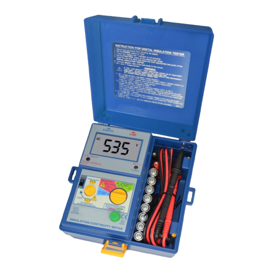
2. Instrument Layout OUTPUT Terminal LCD Display External Voltage Indicator POWER Switch TEST Button POWER Indicator FUNCTION Switch Ω Null Adjust... -
Page 7: Safety Notes
3. Introduction NOTE: This meter has been designed and tested according to safety requirements for electronic measuring apparatus, EN 61010, 1:2001. Follow all warnings to ensure safe operation. WARNING! Read “Safety Notes” before using the meter. 4. Safety Notes 1. Read the following safety information carefully before attempting to operate or service the meter. - Page 8 4. Observe the international electrical symbols listed below: Meter is protected throughout by double insulation or reinforced insulation. Warning! Risk of electric shock. Caution! Refer to this manual before using the meter. Alternating current. 5. Features * 3 ½ digit Insulation Tester * 68 x 34 mm large LCD display * three Insulation test voltage: 250V / 500V / 1000V * external voltage warning indication...
-
Page 9: Measuring Methods
6. Measuring Methods 6.1. Operation caution Observe all safety precautions when the FUNCTION switch is set to either the 200 MΩ (250, 500 V) or the 2000MΩ (1000V) position. Connect the meter test leads to the circuit under test before operating the TEST switch. Do not touch the clip ends of the test leads when the TEST switch is pressed. - Page 10 6.2.3. Before testing always check the following The “battery low” indicator is not shoving. There is no visual damage to the test or test leads. Test Lead Continuity. Select the continuity function and 20Ω range. Short the test leads together. An overrange (“1”) indication will mean that the leads are faulty or instrument fuse is blown.
- Page 11 CAUTION: Never turn the function dial whilst the button is depressed. This may damage the instrument. Never touch the circuit under test during insulation testing. When testing is complete ensure that the test button is released before the test leads are disconnected. This is because the system may be charged up and it must be allowed to discharge through the tester’s internal discharge resistor.
-
Page 12: Specifications
7. Specifications Insulation resistance: Measuring range 200MΩ (250V / 500V DC +/- 10%) Resolution 1 count / 100 kΩ Measuring range 2000MΩ (1000 V DC +/- 10%) Resolution 1 count / 1MΩ Accuracy 1,5% rdg.+5 dgt. (200MΩ range) 3,0% rdg.+3 dgt. (under 1GΩ/2000MΩ) 5,0% rdg.+5 dgt. -
Page 13: Maintenance
Buzzer sound below under 10Ω (on 20Ω range) Withstand voltage meet EN 61010 safety requirements category III Dimensions (WxHxD) 170x165x92 with housing front cover Weight 1,04 kg Standard accessories test leads, alligator clips, carrying belt, batteries and manual 8. Maintenance CAUTION: Always disconnect the test leads from the instrument before attempting battery or replacement. - Page 14 8.3. Statutory Notification about the Battery Regulations The delivery of many devices includes batteries, which for example serve to operate the remote control. There also could be batteries or accumulators built into the device itself. In connection with the sale of these batteries or accumulators, we are obliged under the Battery Regulations to notify our customers of the following: Please dispose of old batteries at a council collection point or...
- Page 15 We herewith confirm that the units are calibrated by the factory according specifications technical specifications. We recommend to calibrate the unit again, after 1 year. ® © PeakTech 05/2012/Ho. PeakTech Prüf- und Messtechnik GmbH - Kornkamp 32 – DE-22926 Ahrensburg / Germany +49-(0) 4102-42343/44 +49-(0) 4102-434 16 info@peaktech.de www.peaktech.de...
Need help?
Do you have a question about the 2670 and is the answer not in the manual?
Questions and answers