Advertisement

USER GUIDE
SYSTEM 3
SYSTEM 21
All references to System 3 apply to
System 21 unless otherwise stated
even if you read nothing else - READ THESE 2 POINTS!
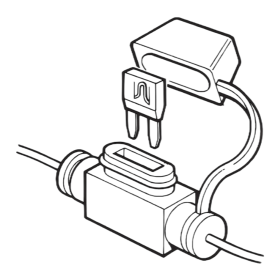
ALWAYS CARRY A SPARE
IN-LINE FUSE
Make sure your installer advises you of
the location of the in-line fuse. If the
fuse fails, your motorcycle will be
immobilised until it is replaced.
KEEP WITH YOUR MOTORCYCLE IN PLASTIC BAG PROVIDED
02005084
06/2003
MAIN SYSTEM COMPONENTS
Two Remote Transmitters
Installed Control Unit
Customising Wires
Installed Protective Trigger Switch
Installed In-Line Fuse and Spare Fuse
Installed LED Alarm Indicator
Warning Labels
WARNING
UNAUTHORISED ALTERATIONS OR
ADDITIONS MAY INVALIDATE THE
WARRANTY AND CERTIFICATE OF
INSTALLATION
Set your own individual
PIN OVERRIDE
This will let you disarm the system if
you lose the remote transmitter.
See pages 6 to 8

Advertisement

Table of Contents
loading

Summary of Contents for Datatool system 3

  • Page 1 Installed In-Line Fuse and Spare Fuse Installed LED Alarm Indicator SYSTEM 3 Warning Labels SYSTEM 21 WARNING All references to System 3 apply to UNAUTHORISED ALTERATIONS OR System 21 unless otherwise stated ADDITIONS MAY INVALIDATE THE WARRANTY AND CERTIFICATE OF INSTALLATION...
  • Page 2: To Disarm The System

    INITIAL OPERATION - STANDARD MODE When you collect your motorcycle, the Datatool System will be armed in STANDARD MODE. In this mode the system arms automatically, 30 seconds after you switch off the ignition. Before moving or starting your motorcycle, You will need to DISARM the system.
  • Page 3 OPERATION OVERVIEW Four elements of the motorcycle are monitored and will initiate a full reaction if any of the following occurs. IGNITION CIRCUIT BATTERY CIRCUIT MOVEMENT TAMPER If the circuit is If any part of the If the motorcycle is If there is any hotwired, or the circuit becomes live,...
  • Page 4 OPERATION - SERVICE/VALET MODE Engage Service Mode when you wish to service or clean your motorcycle, or remove the motorcycle battery. IMPORTANT If after entering service/valet mode you get more than one audible beep every 15 seconds, the system has been triggered in your absence and you have automatically entered diagnostic mode (see diagnostics table on page 9).
  • Page 5: Hazard Warning Lights

    HAZARD WARNING LIGHTS A hazard warning lights function is included. NOTE: When entering Hazard Warning Lights Mode, the hazard warning lights flash 5 times then stop. The motorcycle battery is too low to maintain this mode. To switch off the hazard warning lights, To switch off the hazard warning lights, but leave the system armed, press and disarm the system, press the...
  • Page 6 RIDER OPTION - Siren Tone Selector You can choose one The siren tone will be of eight individual subdued during the siren tones. selection process. RIDER OPTION - Arming the system without Movement/Nudge Function The System can be programmed to arm with the movement/nudge function disarmed (Ferry Mode).
  • Page 7 PIN OVERRIDE - INITIAL PIN ENTRY If your transmitter is lost or damaged, or the transmitter battery is flat, the System can be overriden by a four digit PIN (Personal Identity Number) used in conjunction with the ignition switch. The System is supplied without a PIN. We recommend that you set your own individual four digit PIN as soon as possible.
  • Page 8 PIN OVERRIDE - CHANGE PIN Page 7...
  • Page 9 DISARMING USING PIN OVERRIDE If your transmitter is lost or damaged, or the transmitter battery is flat, the System can be overriden by your four digit PIN used in conjunction with the ignition switch. The PIN facility can only be used after a full alarm reaction has been initiated. Until your transmitter is replaced or repaired, this procedure must be repeated to disarm the system every time it arms.
  • Page 10 SYSTEM REACTION DIAGNOSTICS Reaction Indication If the system has been triggered in your absence, a long audible tone will be heard when the alarm is disarmed with the transmitter. If you wish to establish the reason for the alarm being triggered, enter Service Mode and count the number of beeps emitted from the alarm (see diagnostics table below).
  • Page 11: Troubleshooting

    Starter motor • Check (where applicable) that engine fails to function ‘Run/Stop’ switch is in the ‘run’ position, side (System 3 only) stand is up and motorcycle is not in gear. • Check the motorcycle battery is in good condition.
  • Page 12: Maintenance

    OF INSTALLATION equipment. DATATOOL Products are designed and produced in the UK by Datatool (UK) Ltd Anstey Mill Lane, Alton, Hampshire GU34 2QQ United Kingdom Telephone: +44 (0) 1420 541444 Fax: +44 (0) 1420 541447...

This manual is also suitable for:

System 21

Table of Contents