Table of Contents
Advertisement
Quick Links
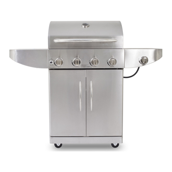
4 BURNER
GAS GRILL
INSTRUCTIONS AND USE
WARNING
Improper installation, adjustment, alteration, ser-
vice or maintenance can cause injury or property
damage. Read this instruction manual thoroughly
before installing or servicing this equipment.
1.
Do not store or use gasoline or other
flammable liquids or vapors in the vicinity
of this or any other appliance.
2.
A liquid propane tank not connected for use
should not be stored in the vicinity of this or
any other appliance.
DANGER
If you smell gas:
1.
Shut off gas to the appliance.
2.
Extinguish any open flames.
3.
Open the lid.
4.
If the odor continues, keep away from the
appliance and immediately call your gas
supplier or fire department.
MANUAL MUST BE READ BEFORE OPERATING!
0316780UVM
Model: PB4GRT
Part: 75204
Important: Read Carefully,
Retain For Future Reference
Advertisement
Table of Contents

Related Manuals for Pit Boss PB4GRT


Summary of Contents for Pit Boss PB4GRT
- Page 1 0316780UVM Model: PB4GRT Part: 75204 Important: Read Carefully, Retain For Future Reference 4 BURNER GAS GRILL INSTRUCTIONS AND USE WARNING Improper installation, adjustment, alteration, ser- vice or maintenance can cause injury or property damage. Read this instruction manual thoroughly before installing or servicing this equipment.
-
Page 3: Table Of Contents
TABLE OF CONTENTS Safety Information ............4 Operating Instructions First Use - Priming the Grill............16 Unpacking The Grill Preheating ................... 16 Parts ....................7 Electronic Lighting Instructions ..........16 Preparation ..................7 Manual Lighting Instructions ..........16 Assembly Instructions Replacing The Battery ..............17 Attaching the Tank Tray Bolt ............. -
Page 4: Safety Information
SAFETY INFORMATION Please read and understand this entire manual before attempting to assemble, operate or install the product. This will ensure you receive the most enjoyable and trouble-free operation of your new gas grill. We also advise you retain this manual for future reference. - Page 5 19. If the information in “17” and “18” is not followed exactly, a fire causing death or serious injury may occur. 20. The natural gas grill and it’s individual shutoff valve must be disconnected from the gas supply piping system during any pressure testing of that system at test pressures in excess of 0.5 PSI (3.5 KPa).
-
Page 6: Unpacking The Grill
UNPACKING THE GRILL... -
Page 7: Parts
PARTS PART DESCRIPTION PART DESCRIPTION Warming Rack Cart Heat Shield Cooking Grate Cart Support Bracket Flame Tamer Locking Caster Right Shelf Base Cart Base Right Shelf Front Cart Support Beam Right Shelf Bracket Door Catch Plate Control Knob Bezel Caster Control Knob Right Cabinet Door Cart Back Panel... -
Page 8: Installing The Casters
2. INSTALLING THE CASTERS Parts Required: Casters (Z) Locking Casters (V) 16 x Screw (BB) 16 x Lock Washers (DD) Installation: • With the cart base (W) laying upside down, attach the 2 casters (Z) as shown to the left side of the cart base (W) using 8 screws (BB) and 8 lock washers (DD). -
Page 9: Installing The Lp Tank Barrier Bar
6. INSTALLING THE LP TANK BARRIER BAR Parts Required: LP Tank Barrier Bar (O) Screw (AA) Installation: • Attach the LP tank barrier bar (O) diagonally to the cart back panel (I) and the cart base (W) using 1 screw (AA) at each end. NOTE: The threaded end of the LP tank barrier bar should point to the cart back panel, fastening from the outside of the cart. -
Page 10: Securing The Grill Head To Cart
10. SECURING THE GRILL HEAD TO CART Parts Required: Grill Head (K) Screw (BB) Installation: • Using a minimum of two people, place the grill head (K) on top of the grill cart. Secure the grill head (K) to the left and right side cart panels (P and B1) using 4 screws (BB). -
Page 11: Assembling The Cabinet Door Handles
14. ASSEMBLING THE CABINET DOOR HANDLES Parts Required: Left Cabinet Door (Q) Right Cabinet Door (A1) Door Handle (R) Door Handle Grommets (S) Screw (EE) Installation: • Attach the cabinet door handle (R) to the left cabinet door (Q) using 2 door handle grommets (S) and 2 screws (EE). -
Page 12: Installing The Side Shelves
17. INSTALLING THE SIDE SHELVES Parts Required: Screw (BB) Lock Washer (DD) Installation: • Starting with the right side, loosen the 2 preinstalled bottom screws (marked “a” and “c” in illustration), and completely remove screw “b”. • Using the shelf keyhole slots, slide the right shelf onto the 2 loosened screws “a”... -
Page 13: Installing The Cooking Components
19. INSTALLING THE COOKING COMPONENTS Parts Required: Warming Rack (A) Cooking Grate (B) Flame Tamer (C) Installation: • Install the 4 flame tamers (C) into the notches directly over the main burners of the grill head (K). • Place the cooking grates (B) onto the ledges above the flame tamers. •... -
Page 14: Connecting To Gas Supply
CONNECTING TO GAS SUPPLY PORTABLE TANK CONNECTION From the front of the cart, place foot ring of 20 lb. tank into the hole in the bottom panel. Make sure the tank valve is in OFF position. Use the tank bolt to secure the tank in a fixed position. Before installing the gas tank, lift up the safety tank ring (Fig.A). Ensure the tank is completely upright, as it is unsafe to operate the grill if the gas tank is not installed properly. -
Page 15: Gas Requirements
To ensure this does not cause difficulty in lighting the grill, follow these instructions: Make sure all burner valves are ”OFF. ” 2. Open the tank valve and wait 5 seconds. SAFEGUARD 4 - TEMPERATURE-ACTIVATED SHUT-OFF The large plastic nut on the regulator assembly is designed in coordination with a check valve in the tank valve to shut off the flow of gas when exposed to temperatures between 240o-300oF (115o-148oC). -
Page 16: Operating Instructions
OPERATING INSTRUCTIONS FIRST USE – PRIMING THE GRILL When firing your grill for the first time, it is advisable to run the main burner(s) on “HIGH” for 20 minutes with the hood down and then turn the main burners off. This tempers the grill. IMPORTANT: Ensure the hood is completely open each time you attempt to light the grill. -
Page 17: Replacing The Battery
Observe that the burner has ignited. Remove the match and extinguish. 8. Repeat steps 2-6 for the next burner. CAUTION: Do not cover the grids during the preheating period. WARNING: Never leave a grill unattended to guard against possible grease fires getting out of control. Grease fires can be severe and cause grill damage, property damage and bodily harm. -
Page 18: Care And Maintenance
CARE AND MAINTENANCE BURNER FLAME CHECK Visually check the burner flames prior to each use. The flames should appear blue. If they do not, refer to the section on cleaning burner tubes and ports. Before cooking on your grill the first time, wash cooking grids and cooking rack with warm, soapy water. - Page 19 the factory supplied hose and regulator must be used. Use only replacement regulator and hose assemblies specified by the manufacturer. LP tank should be securely locked by the patented safety tank ring at all times. An unlocked tank may fall or tilt which can cause injury or property damage.
-
Page 20: Stainless Steel
valve is a safety device required on 20 lb (9.07 kg) propane tanks by the Department of Transportation or the National Standards of Canada, CAN/CSA-B339 Cylinders, Spheres and Tubes for Transportation of Dangerous Goods; and Commission, as applicable, to prevent a catastrophic tank failure due to excessive pressure. LP gas released from the tank is flammable and can be explosive. -
Page 21: Care And Maintenance Time Table
CARE AND MAINTENANCE TIME TABLE Item Cleaning Frequency (Normal Use) Cleaning Method Stainless Steel Surfaces Twice Per Year Stainless Steel Cleaner Cooking Grates After Each Use Burn Off Excess, Wire Brush Stainless Steel Grates 15 Days Scrub Pad & Soapy Water / Dishwasher Safe Grease Cup 15 Days Scrub Pad &... -
Page 22: Replacing The Main Burner
REPLACING THE MAIN BURNER HOW TO REPLACE THE MAIN BURNER FIG.1 Open the grill hood and remove the warming rack (A), cooking grates (B) and flame tamers (C). 2. Remove the cotter pin from the main burner. (Fig. 1) 3. Remove the two screws that attach the main burner electrode and wire to the main burner. -
Page 23: Troubleshooting
TROUBLESHOOTING PROBLEM CAUSE CORRECTIVE ACTION Grill or side cooker The ignition wire came off the Reconnect the ignition wire to the electrical igniter/ will not light. electrical igniter/valve. valve. The distance between the ignition pin Loosen the ignition pin, adjust the distance, then and the burner is greater than 5/32 in. -
Page 24: Replacement Parts
REPLACEMENT PARTS... - Page 25 PART DESCRIPTION PART DESCRIPTION Grill Hood Door Handle Hood Hinge Screw Left Cabinet Door Temperature Gauge Bezel Right Cabinet Door Temperature Gauge Heat Insulating Spacer Match Light Tool Temperature Gauge Match Light Holder Hood Bumper LP Tank Barrier Bar Hood Handle Bezel Heat Insulating Spacer Caster Hood Handle Bezel Locking Caster...
-
Page 26: Warranty
CONDITIONS OF WARRANTY All gas grills by Pit Boss, manufactured by Dansons Inc., carry a limited warranty from the date of sale by the original owner. The warranty coverage begins on the original date of purchase and proof of date of purchase, or copy of original bill of sale, is required to validate the warranty. - Page 27 The serial and model number of your Pit Boss can be found inside the lid of the hopper. Record data in the space below as reference label becomes worn or illegible.
- Page 28 For all other questions, comments, or inquiries, please contact Dansons Inc. directly. Our Pit Boss Grills Customer Service Department is available Monday to Friday 8 am – 5pm MST. Contact Pit Boss Customer Service (English/French) service@pitboss-grills.com TOLL FREE: 1-877-303-3134...
Need help?
Do you have a question about the PB4GRT and is the answer not in the manual?
Questions and answers
where can I order the 4 main burner replacement parts?
I have a Model PB4GRT grill. Can I buy the thermometer Parts 3,4,5 in the manual..