Table of Contents
Advertisement
Quick Links
Advertisement
Table of Contents
Troubleshooting

Related Manuals for Shimadzu AUW220D


Summary of Contents for Shimadzu AUW220D
- Page 1 Presented By Dallas Ft Worth Austin Houston NicolScales.com 800.225.8181 Contact Us Nicol Scales & Measurement is an ISO Accredited Calibration Company that has provided calibration, repair and sales of all types of weighing and measurement products since 1931.
- Page 2 321-56861-21D MAR. 2013 Shimadzu Analytical Balance Instruction Manual AUW-D series AUW220D, AUW120D AUW series AUW320, AUW220, AUW120 AUX series AUX320, AUX220, AUX120 AUY series AUY220, AUY120 Read the instruction manual thoroughly before you use the product. Keep this instruction manual for future reference.
- Page 4 • Shimadzu does not guarantee that the WindowsDirect communication function will operate without problems on all PCs. Shimadzu will accept no responsibility for any trouble that arises as a result of using this function. You are recommended to back up all important data and pro- grams in advance.
-
Page 5: Notation Conventions
Notation Conventions Note This instruction manual uses the following notation conventions to indicate Safety Precautions and additional information. Indicates a potentially hazardous situation that may Caution result in injury to personnel or equipment damage. Provides additional information needed to properly Note use the balance. - Page 6 You could sustain an electric shock or the product could operate abnormally. Prohibitions If you believe that the balance has failed, contact your Shimadzu representative. Use the balance with correct power supply and voltage. Use the balance with the attached AC adapter.
- Page 7 If the balance has to be stored for a long time, store it in the packaging box in which it was delivered. Do not connect anything other than peripheral devices specified by Shimadzu to the balance’s connector. If you do, the balance may stop working normally. Prohibitions In order to avoid trouble, always connect peripheral devices in accordance with the directions in this manual.
- Page 8 The controls implemented as a result of security related require- ments are intended to result in trusted records. Shimadzu CLASS-Balance Agent Shimadzu provides a means for compliance with 21 CFR Part 11 with Shimadzu CLASS-Balance Agent software, part of a compre- hensive laboratory data management system, Shimadzu CLASS Agent.
- Page 9 With your co-operation we are aiming to reduce contamination from waste electronic and electrical equipment and preserve natural resource through re-use and recycling. Do not hesitate to ask Shimadzu service representative, if you require further information. WEEE Mark - VI -...
-
Page 10: Table Of Contents
Contents Introduction ......................Component Names and Functions ................................2.1 Main Components ................... 2.2 Key Panel and Operation 2.3 Balance Display and Functions ................Specifications ....................... Installation ..........................................4.1 Installation Site ..............4.2 Unpacking and Delivery Inspection 4.3 Installation ...................... - Page 11 Contents Setting the Built-in Clock (AUW-D/AUW/AUX series only) ..........................8.1 Date ....................8.2 Date Output Style ........................8.3 Time Display Settings ....................9.1 Bar Graph Display ..........................9.2 Changing the Minimum Display (AUW/AUX/AUY series only) ....9.3 Turning the Backlight On and Off (AUW series only) (Not for AUW-D) Calibration ......................
- Page 12 Contents Units ........................................12.1 Setting Units of Measurement ................12.2 Percentage (%) Conversion Application Functions ..................................13.1 Piece Counting (PCS) 13.2 Solid Specific Gravity Measurement ..............................13.3 Liquid Density Measurement ......................13.4 Auto Print ............ 13.5 Interval Timer (AUW-D/AUW/AUX series only) .....................
-
Page 14: Introduction
The model name can be found in the label placed in front of the weighing chamber. The alphabets in model name indicate its series name. AUW220D and AUW120D are called AUW-D series. Symbols Used in the Manual 1,2,3 …... -
Page 15: Component Names And Functions
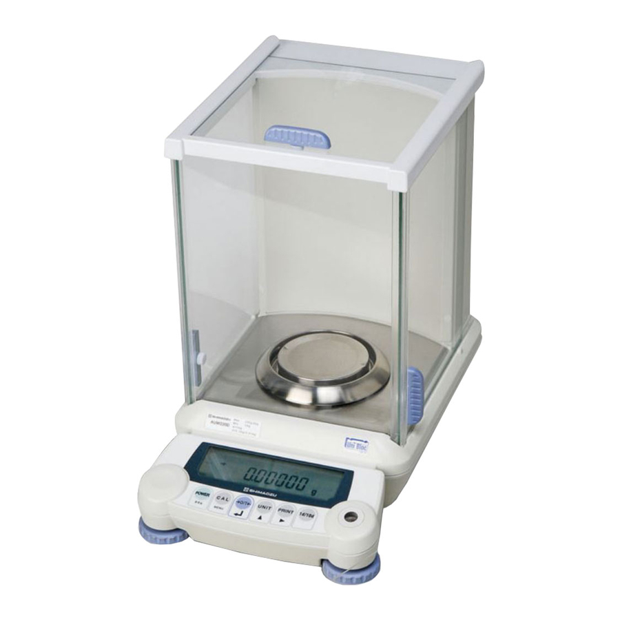
2. Component Names and Functions 2. Component Names and Functions 2.1 Main Components Read these pages before installation Weighing chamber Glass door (3 places) Eliminates the influ- Opens to allow items to be put in ence of air flow. the weighing chamber. Must always be closed when reading the results. -
Page 16: Key Panel And Operation
2. Component Names and Functions 2.2 Key Panel and Operation POWER 1d/10d C A L PRINT UNIT MENU [CAL] key [O/T] key [UNIT] key [PRINT] key [POWER] key [1d/10d] key The following is a list of the functions for each key. During Measurement Pressed once and released Pressed and held for about 3 seconds... -
Page 17: Balance Display And Functions
2. Component Names and Functions 2.3 Balance Display and Functions Bar graph display section Units display section Bar graph display section (Some of the symbols and characters on the balance display are not used by this balance.) Display Name Description Indicates that the weighed value is stable. -
Page 18: Specifications
3. Specifications 3. Specifications AUW-D series Series name AUW series AUX Series AUY series (Dual range type) Model name AUW220D AUW120D AUW320 AUW220 AUW120 AUX 320 AUX220 AUX120 AUY220 AUY120 Capacity 220g/82g 120g/42g 320g 220g 120g 320g 220g 120g 220g... - Page 19 3. Specifications ECTA series name AUW-D series (dual range type) AUW series AUX series AUY series Model name AUW220D AUW120D AUW320 AUW220 AUW120 AUX320 AUX220 AUX120 AUY220 AUY120 Accuracy class Capacity 220g/82g 120g/42g 320g 220g 120g 320g 220g 120g 220g...
-
Page 20: Installation
4. Installation 4. Installation 4.1 Installation Site (1) Power Requirements Select an installation site that is near a power source to allow the use of the attached AC adapter or a site where the special accessory battery pack can be properly used. Verify that the power voltage conforms to that indicated on the AC adapter. -
Page 21: Unpacking And Delivery Inspection
4. Installation • Sites with extreme temperature changes, or high/ low temperature, or high/low humidity. • Sites near flammable or corrosive gases. • Sites with dust, electromagnetic waves, or magnetic fields. Install on a sturdy and level tabletop in the room. Stone is recommended. Rather than the middle of the room, the edges and corners are generally appropriate for vibration-free measurement. - Page 22 4. Installation Explanatory operation sheet Pan supporter Anti-draft ring Instruction manual Balance main body AC adapter Adapter cable holder In-use protective cover Verify that there has been no damage and that the following standard packing items are present. Con- tact your local distributor in case of damaged or missing items. Standard packed items and quantity Standard packed items quantity...
-
Page 23: Installation
4. Installation 4.3 Installation Attach the adapter cable holder. Peel the protective sheet of adhesive off the adapter cable holder , and stick it on the back of the balance as shown in the figure. Place the balance main body on the installation site. - Page 24 4. Installation Attach the In-use protective cover. When the key panel and the display must be pro- tected from dirt and wear, place the cover over the key panel. Note Using a verified balance as a legal measuring instrument in the EU: Legal regulations require a verified balance be sealed.
-
Page 25: Turning On The Power
4. Installation 4.4 Turning On the Power Insert the AC adapter plug in to the DC IN con- nector on the back of the balance. Place the AC adapter cable as shown in figure and hold it with the adapter cable holder. Plug the AC adapter to the power outlet. -
Page 26: Span Calibration
4. Installation 4.5 Span Calibration Note Using a verified balance as a legal measuring instrument in the EU: Span calibration must be performed once the balance is installed and before using the balance as a legal measuring instrument in the EU. The balance must be connected to power and warmed up for at least one hour prior to span calibration and use as a legal measuring instrument. - Page 27 4. Installation For AUY Series Span calibration with external weights Leave the pan with nothing on, in g display mode. Press the [CAL] key once. “E-CAL” will be dis- played. Press the [O/T] key. The zero display will blink. Stability is confirmed after about 30 seconds and (Example) the value of the weight that should be loaded will blink.
-
Page 28: Basic Operation (Read Chapters 1 To 5 For Basic But Proper Operation Of The Balance.)
5. Basic Operation (Read Chapters 1 to 5 for basic but proper operation of the balance.) 5. Basic Operation (Read Chapters 1 to 5 for basic but proper operation of the balance.) Note Before using the balance, warm up thoroughly (at least one hour) and cali- brate. - Page 29 5. Basic Operation (Read Chapters 1 to 5 for basic but proper operation of the balance.) Note • Except when placing or removing items or calibration weights to and from the weighing chamber, keep the glass doors closed unless other- wise described in this manual.
-
Page 30: Changing The Unit Display
0.1mg, press the [1d/10d] key (except for AUW-D series, this key has a different func- tion. 9.2) . When measurement exceeds the small range capacity (82g for AUW220D, 42g for AUW120D) during use of the small range, display automatically switches to the large range. In this case, taring with [O/T] key in the large range will fix the range, and reducing the load on the pan within the small range capacity will not return it to the small range. -
Page 31: For Stable Measurement In Semi-Micro Range (Auw-D Series Only)
5. Basic Operation (Read Chapters 1 to 5 for basic but proper operation of the balance.) 5.4 For Stable Measurement in Semi-micro Range (AUW-D series only) The small range (semi-micro range, minimum display 0.01mg) of AUW-D series dual range balances produces excellent response and stability. - Page 32 5. Basic Operation (Read Chapters 1 to 5 for basic but proper operation of the balance.) Avoid the location where vibration from any machinery is transmitted. Corners of a room are less subject to influence of vibration. Do not use the door of the room. Do not allow other people enter, exit or move in the room. Open glass door minimum.
-
Page 33: Windowsdirect Function
6.2 WindowsDirect Settings Simple settings are made for the balance and the computer. Connection is by RS-232C cable specified by Shimadzu. If bi-directional communication software is used: WindowsDirect function should be turned off. Set up the opti- mal communication parameters for the software according to“14.3 Communication setting”. -
Page 34: Connecting The Rs-232C Cable
6. WindowsDirect Function Notes • When data is outputted to the computer by WindowsDirect function, the effect is the same as “typing the numerical value displayed on the bal- ance and pressing Enter key on the computer’s keyboard”. If you wish the effect of “pressing →... -
Page 35: Setting Up The Computer
6. WindowsDirect Function When using WindowsDirect, use a Null modem cable of one of the below wirings. D-sub9 D-sub25 D-sub9 D-sub25 A cable of hte (1) wiring is available as an optional accessory. RS-232C Cable 25P-9P (1.5m) P/N 321-60754-01 6.2.3 Setting Up the Computer (leave the balance unplugged) Turn ON the power to the computer and start... - Page 36 6. WindowsDirect Function Put a check mark at “Support Serialkey device” in the “General” tab. This should be the only check mark on all the tabs of Accessibility Options unless “Administrative options” appears in the “General” tab. Put check marks at both the items of “Administrative options”...
-
Page 37: Start And Checking Operation
6. WindowsDirect Function 6.2.4 Start and Checking Operation Confirm Windows is free from any application. ® After Windows ® has completely started, con- nect power cable from the AC adapter to the bal- ance, when “oFF” is displayed, press the [POWER] key. -
Page 38: Troubleshooting The Windowsdirect Communication Function
Q1 WindowsDirect communication has been set but it is not operating at all. • Check the type of communications cable used for the connection (Shimadzu authorized part or another part available on the general market) and the soundness of the connection. - Page 39 6. WindowsDirect Function Q5 When data is input into Excel, the cursor doesn't move to another cell. • If a function for conversion to 2-byte characters is available in Windows, turn the setting for this func- tion off. • Click the [Edit] tab under [Options] in Excel and check [Move selection after Enter] (if cells move in response to keyboard input there is no problem).
-
Page 40: Menu Item Selection
7. Menu Item Selection 7. Menu Item Selection 7.1 What is a menu? The AUW-D/AUW/AUX/AUY series is equipped with many useful functions. The menu is provided to allow the operator to efficiently select the functions that meet the operator’s objectives. Understand the menu procedures to gain full command of the functions provided in the AUW-D/AUW/AUX/AUY series. -
Page 41: Menu Item Selection Procedures
7. Menu Item Selection 7.3 Menu Item Selection Procedures See the menu map (Appendix A-1). The AUW-D/AUW/AUX/AUY series menu consists of four levels with the most often used menus in the first level for an easy-to-use structure. The menu can be entered by pressing the [CAL] key from the mass display. - Page 42 7. Menu Item Selection Mass display (Example) Execute the preset calibration method (see 10.2, 10.3.1) WindowsDirect setting (down) (see 6.2.1) WindowsDirect setting (right) (see 6.2.1) (Example) Settings check display (see 7.4.1) Standard mode Pouring mode Settings for Stability and Response (see 11.2) Anti-convection mode High-stability mode Entry to second level...
-
Page 43: Useful Functions Related To Menu
7. Menu Item Selection 7.4 Useful Functions Related to Menu 7.4.1 Settings Check Display From mass display, press the [CAL] key four times to display the confirmation of the current settings. Displayed as abbreviations are the three kinds of environmental settings(see 11.), ON/OFF for the fully-automatic span calibration(see 10.3.2,10.3.3), and ON/OFF for the GLP/GMP/ISO compliant cali- bration report output.(see 10.4.1) Appears when the fully-automatic span calibration... -
Page 44: Menu Lock
7. Menu Item Selection 7.4.3 Menu Lock The menu setting operations can be locked so that the settings cannot be inadvertently changed. This is called Menu Lock. WindowsDirect settings also lock. The menu lock is set with the following proce- dure. -
Page 45: Setting The Built-In Clock (Auw-D/Auw/Aux Series Only)
8. Setting the Built-in Clock (AUW-D/AUW/AUX series only) 8. Setting the Built-in Clock (AUW-D/AUW/AUX series only) AUW-D/AUW/AUX series are installed with a built-in clock. Set the clock before use of Clock-CAL (10.3.3) or Calibration report (10.4.1) functions. Note that the current time is displayed during STAND- BY mode (4.4). -
Page 46: Date Output Style
8. Setting the Built-in Clock (AUW-D/AUW/AUX series only) 8.2 Date Output Style The order of the year, the month and the date in the external output can be selected from three styles. From the mass display, press the [CAL] key repeatedly until “SEttinG”... -
Page 47: Time
8. Setting the Built-in Clock (AUW-D/AUW/AUX series only) 8.3 Time From the mass display, press the [CAL] key repeatedly until “SEttinG” appears. Press the [O/T] key. “CAL dEF” will appear. (Example) Press the [CAL] key repeatedly until “t-HH.MM” appears (HH and MM are each two digits repre- (2:25PM) senting hour and minute, respectively), and press the [O/T] key. -
Page 48: Display Settings
9. Display Settings 9. Display Settings 9.1 Bar Graph Display This function displays a bar graph representation of the load on the pan. This may be used to prevent sudden appearance of “oL” (overload) during measurement. This bar graph display can be turned on or off. -
Page 49: Changing The Minimum Display (Auw/Aux/Auy Series Only)
9. Display Settings 9.2 Changing the Minimum Display (AUW/AUX/AUY series only) Not applicable to a verified balance as a legal measuring instrument in the EU The AUW/AUX/AUY series allow the minimum display to be changed by one digit if desired. The last decimal place will be rounded and removed from the display. -
Page 50: Turning The Backlight On And Off (Auw Series Only) (Not For Auw-D)
9. Display Settings 9.3 Turning the Backlight On and Off (AUW series only) (Not for AUW-D) The AUW series is equipped with a backlight for the display to allow easy viewing regardless of the surrounding lighting conditions. The backlight can be switched on and off. Press the [CAL] key repeatedly from the mass display until “SEttinG”... -
Page 51: Calibration
10. Calibration 10. Calibration 10.1 What is calibration? 10.1.1 The Necessity of Calibration Calibration is required to accurately weigh items with an electric balance. Calibration must be per- formed in these conditions: • When the location of the installation site is changed (even when moved within the same room). •... -
Page 52: Types Of Calibration
10. Calibration 10.1.2 Types of Calibration Terms used in this manual: Span calibration ..Adjustment of the balance sensitivity using two weight values, zero and near-capacity Calibration test ..Comparing the current calibration mass reading to the calibration mass reading after the last span calibration. Calibration .. -
Page 53: Executing Calibration
10. Calibration 10.2 Executing Calibration Perform calibration only after correct installation and thorough warm up. Also, make sure that nothing is on the pan and ensure conditions free from the influence of vibrations or wind. 10.2.1 Span Calibration With Built-in Weight (AUW-D/AUW/AUX series only) “i-CAL”... -
Page 54: Span Calibration With External Weights
10. Calibration 10.2.2 Span Calibration With External Weights “E-CAL” (The balance will be adjusted with external calibration weights) From the mass display, press the [CAL] key once. If the display shows “E CAL” (Preset calibration method is “E-CAL”), jump to Step 4. If the display shows another item (Preset calibra- tion method is not “E-CAL”), go on to Step 2. -
Page 55: Calibration Check With Built-In Weight (Auw-D/Auw/Aux Series Only)
10. Calibration 10.2.3 Calibration Check With Built-in Weight (AUW-D/AUW/AUX series only) “i-tESt” (The balance is checked with the built-in weight but not adjusted.) From the mass display, press the [CAL] key once. If the display shows “i tESt” (Preset calibration method is “i-tESt”), jump to Step 5. -
Page 56: Calibration Check With External Weights
10. Calibration 10.2.4 Calibration Check With External Weights “E-tESt” (The balance is checked with external calibration weights but not adjusted.) From the mass display, press the [CAL] key once. If the display shows “E tESt” (Preset cali- bration method is “E-tESt”), jump to Step 5. If the display shows another item (Preset calibra- tion method is not “E-tESt”), go on to Step 2. -
Page 57: Calibration Settings
10. Calibration 10.3 Calibration Settings One of the following four calibration methods listed in the below step 3 is selected as “preset calibra- tion method”. Preset calibration method will be called with only one key touch from the mass display for convenience of frequent use. -
Page 58: Psc Fully-Automatic Span Calibration (Auw-D/Auw/Aux Series Only)
10. Calibration 10.3.2 PSC Fully-automatic span calibration (AUW-D/AUW/AUX series only) Using a temperature sensor, this function performs fully-automatic span calibration with the built-in weight when a significant temperature change is detected. If PSC turned ON, when there is a temperature change that would influence sensitivity, span calibra- tion executes automatically to maintain the sensitivity of the balance. - Page 59 10. Calibration Setting PSC ON/OFF From mass display, press the [CAL] key repeat- edly until “SEttinG” appears. Press the [O/T] key to display “CAL dEF”. Press the [CAL] key repeatedly until “PSC:∗∗” (Example) appears. The ∗∗ positions show the current set- Setting check ting, either “on”...
-
Page 60: Clock-Cal Fully-Automatic Span Calibration (Auw-D/Auw Series Only)
10. Calibration 10.3.3 Clock-CAL Fully-automatic span calibration (AUW-D/AUW series only) The balance can be set to execute fully-automatic span calibration at set times (up to three times a day) with the built-in weight and the built-in clock. Clock-CAL is a very convenient function, when cali- bration reports are desired for regular calibrations, or to schedule span calibrations during break times to avoid interruption of measurement work. - Page 61 10. Calibration Setting the time for Clock-CAL From mass display, press the [CAL] key repeat- edly until “SEttinG” appears. Press the [O/T] key to display “CAL dEF” Press the [CAL] key repeatedly until “tCAL t∗” (Example) appears. Press the [O/T] key to display “t∗ HH:MM”.
-
Page 62: Pcal: Calibration Of The Built-In Weight (Auw-D/Auw/Aux Series Only)
10. Calibration 10.3.4 PCAL: Calibration of the Built-in Weight (AUW-D/AUW/AUX series only) Not applicable to a verified balance as a legal mea- Note suring instrument in the EU. The built-in calibration weight is already calibrated before shipping but the operator can also calibrate the built-in calibration weight using their own external calibration weights. -
Page 63: Inputting External Calibration Weight Value For E-Cal
10. Calibration 10.3.5 Inputting External Calibration Weight Value for E-CAL The exact value (conventional mass value) of the operator’s calibration weight to be used for E-CAL and E-tESt procedures can be entered. From mass display, press the [CAL] key repeat- edly until “SEttinG”... -
Page 64: Inputting External Calibration Weight Value For Pcal
10. Calibration 10.3.6 Inputting External Calibration Weight Value for PCAL Not applicable to a verified balance as a legal mea- Note suring instrument in the EU. The exact value (conventional mass value) of the operator’s calibration weight to be used for PCAL procedure can be entered. -
Page 65: For Glp/Gmp/Iso Compliance
10. Calibration 10.4 For GLP/GMP/ISO Compliance 10.4.1 Calibration Report Setting Setting the calibration report provides an automatic calibration record output every time span calibra- tion or calibration test is performed. An optional electronic printer (see 14.1) can save reports by print- ing them.Combination with Clock-CAL function (see 10.3.3) provides fully-automatic and periodical calibration and reports. -
Page 66: Balance Id Setting
10. Calibration 10.4.2 Balance ID Setting This setting is for the balance ID number that is output along with the calibration report. From mass display, press the [CAL] key repeatedly until “SEttinG” appears. Press the [O/T] key. “CAL dEF” appears. (Example) Press the [CAL] key repeatedly until “id: ∗∗∗∗”... -
Page 67: Date Printout Setting
10. Calibration 10.4.3 Date Printout Setting This setting determines whether or not the date and time on the balance’s built-in clock is printed out along with the calibration report. From mass display, press the [CAL] key repeatedly until “SEttinG” appears. Press the [O/T] key. -
Page 68: Environment Settings
11. Environment Settings 11. Environment Settings 11.1 What are environmental settings? The response and other settings can be changed to adapt to the installation environment (for example, unavoidable vibrations or air currents) or measurement uses (for example, depending on whether solid objects, liquids, or powders are to be measured). -
Page 69: High-Stability Mode
11. Environment Settings Anti-convection mode adjusts the timing of appear- ance of the stability mark. Note that when Anti-convec- tion mode is selected, the stability mark will take longer to appear. From the mass display, press the [CAL] key repeat- Settings Check Display edly until “ConvECt”... - Page 70 11. Environment Settings Environmental setting menu Or, press [CAL] key once or twice to display “StAbL.Env” (for very stable environmental condition) or “UnStb.Env” (for unstable environmental condition). Pressing [O/T] key at each display will select that environmental set- ting. (when normal is selected) It is recommended to set “StAbL.Env”...
-
Page 71: Stability Detection Band
11. Environment Settings 11.3 Stability Detection Band The appearance of the Stability Mark ( ) indicates that the mass display has been stabilized. The condition for judging stability is user-selectable. When the stability detection band is set to 1, the stabil- ity mark appears when the mass display stays within 1 count for a set period of time. -
Page 72: Zero Tracking
11. Environment Settings 11.4 Zero Tracking Using the zero tracking function allows the display to be kept at the current zero point by automatically canceling slight drifts from the zero point caused by environmental conditions. When measuring very slow change in mass such as liquid droplets and evaporation processes, it is recommended to turn zero tracking OFF. -
Page 73: Stability Mark Lighting Timing
11. Environment Settings 11.5 Stability Mark Lighting Timing Stability Mark Lighting Timing can be selected according to use or demand accuracy. When “Stability Mark Lighting A Stability Mark lights up at the same time stability is detected. Timing” is set to [FASt] Although it becomes easy to change the measurement value after Stability Mark lighting, since many samples are measurable one after another, the increase in efficiency of working can be attained. -
Page 74: Units
12. Units 12. Units The AUW-D/AUW/AUX/AUY series allow display of various mass units. Units that are registered beforehand can be called by simply pressing the [UNIT] key when in mass display. The default units are gram, percentage, PCS, and carat. In order to use the other units included in the AUW-D/AUW/AUX/AUY series, register the units beforehand according to section 12.1. - Page 75 12. Units ∗ “U- SporE” Singapore tael ∗ “U- tiwAn” Taiwan tael ∗ “U- ,mAL” Malaysia tael ∗ “U- ChinA” Chinese tael ∗ “U- dwt” Pennyweight ∗ “U- GN” Grain ∗ “U- m” Mesghal “U- b” Baht ∗ “U- t” Tola ∗...
-
Page 76: Percentage (%) Conversion
12. Units 12.2 Percentage (%) Conversion Setting a standard sample to 100% allows percentage conversions. Register percentage unit beforehand. (See 12.1.) Percentage unit is registered by default. Therefore, registration is not required if the default setting has not been changed. (Example) From the mass display, press the [UNIT] key repeatedly to switch to the % display. -
Page 77: Application Functions
13. Application Functions 13. Application Functions 13.1 Piece Counting (PCS) Register PCS as one of the units beforehand. (See 12.1.) PCS is registered by default. There- fore, registration is not required if the default set- ting has not been changed. From the mass display, press the [UNIT] key (Example) repeatedly to switch to the PCS display. -
Page 78: Solid Specific Gravity Measurement
13. Application Functions 13.2 Solid Specific Gravity Measurement Solid specific gravity measurement computes the density (or specific gravity) of a solid sample by mea- suring its weight in air and in a liquid of known density (or specific gravity). The following is the procedure when using a hanging pan, a tank and a table allowing below balance weighing, prepared by the operator. - Page 79 13. Application Functions (e) Select either the hold display mode or the con- tinuous display mode for the specific gravity value display. Press the [CAL] key repeatedly until [SG Hold] appears. Each time the [O/T] key is pressed the “ ”...
- Page 80 13. Application Functions Place the items to be measured on the (Example) immersed hanging pan. The display shows the weight value in water. Press the [CAL] key to (Example) show the specific gravity value in the set specific gravity value display mode. (Hold display mode example) Press the [POWER] key to return to 9.
-
Page 81: Liquid Density Measurement
13. Application Functions 13.3 Liquid Density Measurement Liquid density measurement computes the density of a liquid by measuring the weight of a sinker (solid) with a known volume in air and in the liquid. The following is the procedure when using a hanging pan, a tank and a table allowing below balance weighing, prepared by the operator. - Page 82 13. Application Functions (e) Select either the hold display mode or the con- tinuous display mode for the specific gravity value display. Press the [CAL] key repeatedly until [SG Hold] appears. Each time the [O/T] key is pressed the “ ”...
- Page 83 13. Application Functions Place the sinker on the immersed hanging pan. (Example) The display shows the weight value in liquid. Press the [CAL] key to show the liquid density in (Hold display mode example) the set specific gravity value display mode. Press the [POWER] key to return to 9.
-
Page 84: Auto Print
13. Application Functions 13.4 Auto Print Using Auto Print allows measurement results to be automatically output via the RS-232C connector or DATA I/O connector without pressing the [PRINT] key with every measurement. This function can be combined with WindowsDirect (see 6.). When Auto Print is activated, if a sample weighing 10 counts or more is placed on the pan while the mass displayed is within ±5 counts of zero, the result is output via the RS-232C cable or DATA I/O connector automatically upon display stabilization. -
Page 85: Interval Timer (Auw-D/Auw/Aux Series Only)
13. Application Functions 13.5 Interval Timer (AUW-D/AUW/AUX series only) Not applicable to a verified balance as a legal measuring instrument in the EU This function automatically outputs the measurement values of the balance at set time intervals. (Example) Press the [CAL] key repeatedly from the mass display until “FUnC.SEL”... - Page 86 13. Application Functions Note No more than one of the four application modes, Auto Print (13.4), Interval Timer (13.5), Add-on Mode (13.6), Formulation Mode (13.7), can be set ON at the same time. Notes • The [O/T] key can always be used for taring. •...
-
Page 87: Add-On Mode
13. Application Functions 13.6 Add-on Mode This function is convenient for making many measurements of minute samples. This function automati- cally output the measurement valve and tare after a sample is placed on the pan and the stability mark displays. Pressing the [POWER] key displays and output the total. Setting (Example) Press the [CAL] key repeatedly from the mass... - Page 88 13. Application Functions Operating Add-on Mode When the Add-on Mode is set on and ready for start, the Add-on symbol and the Standby mark are illumi- (Ready for start) nated in the mass display. In the Add-on Mode, place the container (if used) on the pan and press [O/T] key to tare.
- Page 89 13. Application Functions Press the [POWER] key. The measurements up to this point are summed up and displayed on the balance and outputted. Clear the pan. ---ADDON MODE--- The balance is ready for the next set of measure- CMP001 = ments at before step 1.
-
Page 90: Formulation Mode
13. Application Functions 13.7 Formulation Mode This function is convenient for making many measurements of minute samples and seeking the total mass. In this mode with any unit, when a sample is placed on the pan and [PRINT] key is pressed, that value is output via the RS-232C cable or DATA I/O connect and automatic taring is performed each time afterwards. - Page 91 13. Application Functions (Operating Formulation Mode) When the Formulation Mode is set on, the add-on symbol and the Memory symbol are illuminated in the mass display. In the Formulation Mode, place the container (if used) on the pan and press [O/T] key to tare. (Taring is accepted only before weighing the first sample.) Place the sample (first component) in the con- tainer and press [PRINT] key.
-
Page 92: Communication With Peripheral Devices
14. Communication with Peripheral Devices 14. Communication with Peripheral Devices 14.1 Electronic Printer EP-80 The AUW-D/AUW/AUX/AUY series allows connection to Electronic Printer EP-80. When using EP-80, follow these procedures for connecting to the balance. Set the communication status of the balance to F1 (standard settings 1). -
Page 93: Personal Computer - Rs-232C
14. Communication with Peripheral Devices 14.2 Personal Computer - RS-232C Programming with the command codes makes it possible to control the balance from a computer. When the balance does not have to be controlled by the computer, WindowsDirect (see 6.) offers very handy data transmission. -
Page 94: Data Format
14. Communication with Peripheral Devices 14.2.2 Data Format Data format 1 (“F-dF1” in menu item selection) is the Shimadzu’s standard data format. (See 14.3.3.5) The following is the details of this data format. (1) Basic format An example of data format for a negative weight value (-21.6865g) with delimiter of C/R is shown. - Page 95 14. Communication with Peripheral Devices (iii) When the delimiter “C/R+L/F” is selected (Refer to 14.3.3.2) The delimiter information requires one more character. Therefore one more byte is added after Position No.13 in the above example. Consequently, the data becomes 1 byte longer. (3) Data format in case of “oL”...
-
Page 96: Command Codes
14. Communication with Peripheral Devices 14.2.3 Command Codes Caution Inputting characters and command codes not shown here into the balance may not only alter the previous settings but may also impair proper mea- surement. If by mistake characters or commands not shown here are entered into the balance, immediately unplug the power supply cable and wait about ten seconds before plugging it in again. - Page 97 14. Communication with Peripheral Devices Command Code Function Description g, % switching g unit removal ∗ - mg mg unit removal - PERCENT % unit removal - PCS Piece counting removal - CT ct unit removal ∗ - MOM Monme unit removal - SDENCE Solid specific gravity removal Liquid specific gravity...
-
Page 98: Communication Settings
Compatible Data Hand- Baud rate Delimiter (and bit Stop bit item manufacturer format shake length) selection Standard set- Shimadzu None (8) Hardware iF:F1 1200 ting 1 (standard) Standard set- Shimadzu None (8) Hardware iF:F2 1200 ting 2 (extended) -
Page 99: User Setting
14. Communication with Peripheral Devices (Selecting one of standard Settings) From the mass display, press the [CAL] key repeatedly until the [intFACE] display appears. Press the [O/T] key. The display shows “iF;F1” (When F1 is selected) If necessary, press the [CAL] key repeatedly until the desired standard setting display appears. - Page 100 14. Communication with Peripheral Devices 14.3.3.1 Communication speed settings (1) The display changes from “io.b:∗∗∗∗” to “b-300”. Pressing the [CAL] key cycles through the available settings. The stability mark ( ) appears, when the current setting is displayed. Display during b-300 b-600 b-1200...
- Page 101 Display during F-dF1 F-dF2 F-dF3 F-dF4 setting Data format 1. Data format 2. Data format 3. Data format 4. Setting specifics Standard Shimadzu Extended format Same format Same format format. from data format 1. Mettler balances. Sartorius balances. (2) When the desired setting appears, press the [O/T] key.
-
Page 102: Decimal Point Symbol In Output Data
14. Communication with Peripheral Devices 14.4 Decimal Point Symbol in Output Data The AUW-D/AUW/AUX/AUY series offers choice of decimal point symbols in the outputted data to a computer or an electronic printer. The decimal point can be expressed with either “.” (period) or “,” (comma) depending on your preference. -
Page 103: Maintenance And Transport
15. Maintenance and Transport 15. Maintenance and Transport 15.1 Maintenance Cleaning Clean by wiping with a soft cloth soaked in neutral detergent and wrung tightly. The pan can be washed in water. Dry it thoroughly before attaching it to the balance. The side glass doors can be removed to allow cleaning and replacement of the door rail. - Page 104 15. Maintenance and Transport Slide the glass door out backwards. • In the AUW-D/AUW/AUX/AUY series, when the door rails of the side glass doors become dirty or worn, the rails can be replaced. Removing the door rail Remove the glass door. Press down the outer edge of the door rail with a pointed thing for lifting the door rail.
-
Page 105: Transport
15. Maintenance and Transport 15.2 Transport … Remove the anti-draft ring, the pan, and the pan supporter from When moving by hand the weighing chamber. Lift the main body as shown in the figures and carry it securely in both hands. When using other methods …... -
Page 106: Troubleshooting
16. Troubleshooting 16. Troubleshooting 16.1 Error Code Displays Error code display Description Countermeasures The zero point shift is large during cali- Remove items from the pan. CAL E2 bration. In order to postpone calibration, press [POWER] key. CAL E3 Large span error in PCAL Use the correct calibration weight. -
Page 107: Troubleshooting
16. Troubleshooting 16.2 Troubleshooting When Symptom Possible Causes Countermeasures Before Nothing appears in the The AC adapter is not securely Check power supply and connect measurement display. connected. The power switch- correctly. board of the room is turned off. The power voltage is incorrect. During The display fluctuates. -
Page 108: Appendices
Appendices Appendices A-1. Menu map in brackets after the menu item shows reference section number) • [CAL] key: Pressing the [CAL] key moves to the next menu in the current hierarchy. ( in the diagram below) • [O/T] key: Pressing the [O/T] key moves the current hierarchy to the menu of one hierarchy down. in the diagram below) When no menu exists in the hierarchy below, this command is fixed. - Page 109 Appendices Preset / delete GN unit Preset / delete Mesghal unit Preset / delete Baht unit Preset / delete Tola unit Preset / delete Parts pound unit ( 13.4) AtPrt: on Autoprint function 0.0000 Ap-on Ap-oF ( 13.5) *1,*5 Interval timer setting ( 9.1) AdiSP: on Bar graph display setting...
- Page 110 Appendices ( 10.4.3) Date, time printout Prtdt: on Date, time printout on Prtdt-on Date, time printout off Prtdt-oF Decimal point symbol in ( 14.4) output data dECPt: Pr ".": Period dECPt-Pr ",": Comma dECPt-Cn ( 7.4.2) rESEt Menu reset rESEt? Menu reset confirmation ( 14.3.2) Mass Display...
-
Page 111: A-2. Standard Accessories And Maintenance Parts List
Appendices A-2. Standard Accessories and Maintenance Parts List Part name Part number Remarks 321-41225 Pan supporter assembly 321-62933 With rubber cushions Anti-draft ring 321-62903 AC adapter Contact your distributor Level screw 321-62884 Glass door assembly (right) 321-62932-02 Includes handle Glass door assembly (left) 321-62932-01 Includes handle Glass door assembly (top) -
Page 112: A-4. Specifications For Rs-232C Connector
Appendices Note The number and specifications noted here are subject to change without notice. The RS-232C cables are not guaranteed to match every computer or device. Also, their lock screws may not match the connector threads on the balance. A-4. Specifications for RS-232C Connector RS-232 Specifications Pin number Name... -
Page 113: A-5. Table Of Unit Conversion Constants
Appendices A-5. Table of Unit Conversion Constants The following conversions are used to display in various mass units. = 1000 mg = 5 ct = 0.266667 mom = 0.00220462 Lb = 0.0352740 Oz = 0.0321507 Ozt = 0.0267173 TL-HK = 0.0264555 TL-Singapore = 0.0266667 TL-Taiwan = 0.0264600 TL-Malaysia = 0.0266071 TL-China... -
Page 114: A-6. Performance Check Guide
Appendices A-6. Performance Check Guide Not applicable to a verified balance as a legal measuring instrument in the EU Notes • The following is a standard guideline used to determine whether the bal- ance is working properly. The specific criterion can be set according to each user’s requirements. - Page 115 Appendices Compute Rx and Ry according to the expres- sions given above. Rx and Ry values within 1.0mg are normal. (In the small range of AUW-D series, within 0.30mg. ) Cornerload Performance (four-corner error) For AUW-D series, conduct this check in Warm up the balance thoroughly.
-
Page 116: A-7. Below-Weigh Hook Dimensions
Appendices A-7. Below-weigh Hook Dimensions (Unit: mm) sensor Below-weigh hook Balance bottom Below-weigh hook... -
Page 117: A-8. Index
Appendices A-8. Index .......... 12, 34 current time ........9, 12, 98 AC adapter ..........98 accessories ..........81 data format ..........4, 74 add-on mode ..........32, 33, 54 date ..........55 air currents ........2, 12 DC IN connector analog display bar graph display ........ - Page 118 Appendices ..........63 percentage ........101 performance check ........... 79 peripheral ... 50, 51 Inputting external calibration weight value ........80 personal computer ........7, 10, 38, 40 installation ..........64 piece counting ..........72 interval timer ..........56 pouring mode .........
- Page 119 Appendices ............34, 48 time ..........72 time interval .............92 transport ........7, 13, 55, 56 vibration .......25, 93, 94 troubleshooting ........39 types of calibration ....12, 13, 15, 40, 45, 49, 102 warm up ............. 37 warm-up ............17, 61 unit ...... 2, 10, 15, 90 weighing chamber ..........100 unit conversion...
Need help?
Do you have a question about the AUW220D and is the answer not in the manual?
Questions and answers