Table of Contents
Advertisement
Quick Links
Advertisement
Table of Contents
Troubleshooting

Related Manuals for Shimadzu UPX Series


Summary of Contents for Shimadzu UPX Series
- Page 1 Presented By Dallas Ft Worth Austin Houston NicolScales.com 800.225.8181 Contact Us Nicol Scales & Measurement is an ISO Accredited Calibration Company that has provided calibration, repair and sales of all types of weighing and measurement products since 1931.
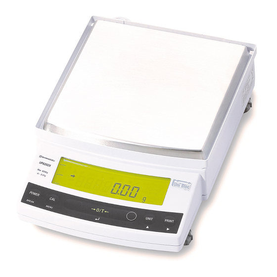
- Page 2 S321-78282 Aug. 2019 Top-loading Balance Foreword UPX Series Name and Function of Components UP223X, UP423X, UP623X, UP823X, UP1023X UP422X, UP822X UP2202X, UP4202X, UP6202X Installation UP4201X, UP8201X UPY Series Basic Operation UP223Y, UP423Y, UP623Y, UP823Y, UP1023Y UP422Y, UP822Y Menu Item Selection...
- Page 3 No text...
- Page 4 • Shimadzu does not guarantee that the serial communication functions will operate without problem on all PCs. Shimadzu will not accept responsibility for any trouble that arises as a result of using this function. It is recommended that all important data and programs are backed up in advance.
- Page 5 Foreword Notation Conventions Used within the Instruction Manual The instruction manual uses the following notation conventions in accordance with the degree of risk and damage to equipment. Notation Description Indicates a potentially hazardous situation which, if not avoided, ! Caution may result in minor to moderate injury or equipment damage.
-
Page 6: Up Series
UP1023X UP1023Y UP422X UP422Y UP822X UP822Y UP2202X UP2202Y UP4202X UP4202Y Large pan type UP6202X Large pan type UP6202Y UP4201X UP4201Y UP8201X UP8201Y For information on the following points, please contact your Shimadzu Balance representative. • Product warranty • After service... -
Page 7: Safety Precautions
Safety Precautions Precautions on Use To be strictly observed To ensure that you use the balance safely and correctly, read the following precautions carefully. The details listed below provide important information on safety, and must be observed at all times. ■... -
Page 8: Precautions Related To Installation Work
Precautions Related to Installation Work CAUTION Do not connect anything other than peripheral devices specified by Shimadzu to the balance’s connector. Prohibitions If you do, the balance may stop working normally. In order to avoid trouble, always connect peripheral devices in accordance with the directions in this manual. -
Page 9: Caution Labels
Cautions labels are placed in necessary locations on the balance to ensure that it is used correctly. In the event of these labels being mislaid or damaged, contact a Shimadzu sales office or service agency to request new labels, and then make sure they are situated in the correct locations. -
Page 10: Residual Risk Information
Safety Precautions ■ Residual Risk Information Residual risk refers to the risks that could not be removed or reduced during the design and manufacturing stages. Check the [Residual Risk Maps] for each area with inherent risks and implement protective measures while referring to the [List of Residual Risks]. - Page 11 The company can also not be held responsible for damages relating to damage compensation caused to users by third parties. 2) The liability for compensatory damages attributable to Shimadzu is limited to a sum equivalent to the cost of the product in all cases.
-
Page 12: Aftercare Services And Part Supply Period
• See [Chapter 13. Maintenance/Inspections] for details on daily inspections and part replacement. • Contact a Shimadzu sales office or service agency, or one of Shimadzu’s service companies to request Periodic inspections and regular calibrations. Product Disposal When disposing of the product, dismantle and dispose of the parts separately in accordance with their composition in order in consideration of environmental conservation. -
Page 13: Shimadzu Balances And 21 Cfr Part 11
The controls implemented as a result of security related requirements are intended to result in trusted records. Shimadzu Lab Solutions Balance Shimadzu provides a means for compliance with 21 CFR Part 11 with Shimadzu Lab Solutions Balance software, part of a comprehensive laboratory data management system, Shimadzu Lab Solutions. Ask your Shimadzu representative about it. -
Page 14: Table Of Contents
Weight (UPX Series Only) ..32 Product Disposal ..........IX 7.2.2 Calibration Check Using the Built- Shimadzu Balances and 21 CFR Part 11 ....X in Weight (UPX Series Only) ..33 Action for Environment (WEEE) ......X 7.2.3 Span Calibration Using External Table of Contents ........XI... -
Page 15: Table Of Contents
Table of Contents 8.3.2 Timing of Stability Mark 12.5.3 Format ........88 Illumination and Data Output ..46 12.5.4 Communication Speed ..... 88 Tracking ..........46 12.5.5 Parity / Bit Length ..... 88 12.5.6 Stop Bit ........89 Unit Display Set-up ......47 12.5.7 Delimiter ........ -
Page 16: Name And Function Of Components
Name and Function of Components Components a. Large pan model Large pan windbreak Even light breezes can have an effect on measurements, so the windbreak protects against wind. Supports the object to Label The windbreak is not included with models be weighed Shows model name. - Page 17 . Name and Function of Components a,b. Common Transportation screws (only for UPX Series) Ground terminal Connect this terminal to ground if necessary Theft preventing ring KEY Connector 下皿フックキャ ップ Below-weigh hook cap RS-232C DATA I/O DC IN Connector Connector...
-
Page 18: Key Panel And Operation
. Name and Function of Components Key Panel and Operation [POWER] key [CAL] key [O/T] key [UNIT] key [PRINT] key Functions of the keys During Weighing Press Once and Release Press and Hold for About 3 Seconds Switches between the operation and standby Exits the application function and returns to [POWER] modes. -
Page 19: Balance Display And Function
. Name and Function of Components Balance Display and Function %NETBPTG PCS lbGN mg mom ctdwt oztl BATT WARM-UP STAND-BY Analog display section Unit display section Display Name Description Indicates that the weighed value is stable. (*1) In menu item selection, this Stability mark symbol indicates currently selected item. -
Page 20: Installation
Installation Choosing the Installation Site Power supply Select an installation site with a power source that allows for proper use of the included AC adapter. Verify that the supply power voltage conforms to that indicated on the AC adapter. Installation site ! Caution Avoid sites where the balance will be exposed to the following: •... - Page 21 . Installation • Extreme temperature, temperature changes or humidity • Corrosive or flammable gasses • Dust, wind, electromagnetic waves, or magnetic fields Install the balance on a strong and stable flat table or floor in the room. Large capacity balances should be installed on a sturdy floor and table that can support the total load of the balance and object to be weighed.
-
Page 22: Unpacking And Delivery Inspection
. Installation Unpacking and Delivery Inspection Unpack and remove all the items from the delivery box. Check if all the listed items are present and nothing has been damaged. Contact your local distributor in case of damaged or missing items. Contact information is provided on Last page. - Page 23 . Installation a. Large pan model ■Pan ■Large pan windbreak ■Operation explanation sheet (0.01 g models only) ■Pan supporter caps ■In-use protective cover ■Instruction manual ■Balance main body ■AC adapter (The shape of the adapter supplied with the balance may differ from this gure.) ■Screw Driver...
- Page 24 . Installation b. Small pan model ■Windbreak Lid (minimum display0.001g models only) ■Windbreak Main (minimum display0.001g models only) ■Pan ■operation explanation sheet ■Pan supporter caps ■In-use protective cover ■Instruction manual ■Balance main body ■AC adapter (The shape of the adapter supplied with the balance may differ from this figure.) ■Fixing knobs for windbreak ■Stainless screws ■Screw Driver...
-
Page 25: Installation
. Installation Installation Start at step when installing a UPY Series balance. Prepare a plus (+) screw driver for a UPX Series balance. Place the balance main body upside down. (UPX only) ! Caution Do not operate step with the balance placed on its side. - Page 26 . Installation This balance has three level screws (adjustable feet) at the right front, left front and right rear Level indicator corners. Turning a level screw clock-wise stretches the leg to raise the balance body there. Turning ③ anticlockwise withdraws the leg and lowers the balance body.
- Page 27 . Installation Install the pan. With small pan model with minimum display of 0.001g, the standard windbreak is also installed here. a. Large pan model (1) Insert the four pan supporter caps into the Positioners Large pan windbreak holes in the top of the balance. (0.01 g (2) Next, align the large pan windbreak with models only)
- Page 28 . Installation (2) Fit windbreak main on top of the balance main body, and fasten it with two fixing knobs. In cases where there is any risk of organic solvents coming into contact with the main body, use the included stainless steel screws to fasten the windbreak instead of the fixing knobs.
- Page 29 . Installation If you use in-use protective cover, peel off the paper to expose the adhesive on it, then fit it on the display and key part. Press the adhesive parts gently. Note Using a verified balance as a legal measuring instrument in using region: Legal regulations require a verified balance be sealed.
-
Page 30: Turning On The Power
. Installation Turning on the Power Insert the AC adapter plug into the DC IN connector on the back of the balance. Insert the AC adapter into the power source. The balance self-check is activated and the following messages are displayed in the order indicated. -
Page 31: Span Calibration
In order to ensure this stability, turn the power to the g display for at least 1 hour and allow the temperature of the balance to stabilize after installation, before carrying out calibration. UPX Series [Span Calibration Using the Builtin Weight] Verify that the balance is in gram-display and that the pan is empty. - Page 32 . Installation UPY Series [Span Calibration Using External Weights] Note Not applicable to a verified balance as a legal measuring instrument in using region. Verify that the balance is in gram-display and unload the sample from the pan. Press the [CAL] key once. “E-CAL” is displayed. Press the [O/T] key.
- Page 33 . Installation When the zero display blinks, unload the weight from the pan and press the [O/T] key. [SEt], [CAL End] is displayed briefly to indicate completion of span calibration. Then the gram- display will return. Note Span calibration should be performed again : when the location of the balance is changed, when the room temperature changes considerably, periodically, according to the quality control plan of the user.
-
Page 34: Basic Operation The Balance Can Be Used Correctly According To The Content Of Chapters 1 To 4
Basic Operation The balance can be used correctly according to the content of Chapters 1 to 4 Weighing If a weighing vessel (tare) is used, place it on the pan and wait for the stability mark to prompt. Once the display stabilizes, press the [O/T] key. This will zero the display. -
Page 35: Changing The Unit Display
. Basic Operation Note Using a verified balance as a legal measuring instrument in using region: The balance must be used within the temperature range indicated on the verification label. When PSC (refer to 7.3.2), fully-automatic span calibration, is not activated, operator must carry out span calibration with the built-in weight (refer to 2.5) upon blinking of the Weight Symbol. -
Page 36: Menu Item Selection (Read Chapters 8.2 4 To 12 Before Using The Balance)
Menu Item Selection (Read Chapters 4 to 12 before using the balance) What is the Menu? The UP Series is equipped with a number of useful functions. Menus are provided to allow customers to efficiently select the functions suited to their usage purposes and configure optimal settings. Configuration of these settings is referred to as "menu settings". -
Page 37: Menu Item Selection Procedure
. Menu Item Selection Menu Item Selection Procedure Refer to Menu Maps (explanatory operation sheet and A2. at the end of this document). UP Series menus are composed of 4 menu levels. Press the [CAL] key three times during mass display to open the menu. - Page 38 . Menu Item Selection Press the [CAL] key 2 times to display the next item. The display will show [Eb-4]. Important Note on Menu Item Selection Even the desired menu item is reached and displayed, it is not yet set unless Stability mark ( ) is prompted with it.
- Page 39 . Menu Item Selection Exiting from menu settings Press and hold the [POWER] key for approximately three seconds during menu settings to return to mass display.
-
Page 40: Setting Numeric Values
. Menu Item Selection Setting Numeric Values In the UP Series, various settings such as external sensitivity calibration weight value input, checkweighing for setting threshold values, and medium density during specific gravity measurement, are input as numerical values in some cases. (see 8.2, 8.3, 11.1, 11.5, 11.7 for detail of each item.) In a menu used to set numeric values, [MENU] and [ ] are both prompted and the digit to be input blinks. -
Page 41: Related Useful Functions
. Menu Item Selection Related Useful Functions 4.5.1 Last Menu Recall This function is convenient when an application requires frequent changes to a specific menu item. During mass display or menu selection, press and hold the [CAL] key for approximately three seconds. The last menu item that was changed or set is displayed. -
Page 42: Menu Lock
. Menu Item Selection 4.5.3 Menu Lock In the UP Series, menu settings can be locked to prevent any accident or erroneous menu changes. This feature is called "Menu lock". Menu Lock can be activated or released only at the “oFF” display immediately after the balance is connected to the power. -
Page 43: Built-In Clock Set-Up
Built-in Clock Set-up The built-in clock has to be set up in advance if a calibration record is to be produced or Clock-CAL function is to be used. Date Select menu , and set the last two digits of the year, the month, and the day, in that order. Press the [UNIT] key to increase the blinking (selected) digit by 1. -
Page 44: Time
. Built-in Clock Set-up Time Select menu item and set the time in the 24 hour system using the [UNIT] and [PRINT] keys, then press the [O/T] key. Example: 1:23 in the afternoon, is set as “13:23”. (Example) Note The moment the [O/T] key is pressed seconds are set to 00. Setting Display During Stand-by Determine what is to be displayed during stand-by. -
Page 45: Display Selection
Display Selection Bar graph display The relative amount of the load on the pan is displayed in the bar graph. This feature helps to prevent errors due to OL (overload) status. This display can not be used with the Check weighing or Target mode. A bar displayed in the lower areas of the scale (Examples) indicates that the load on the pan is small. -
Page 46: Calibration
[i-CAL x] [i-tESt x] [wAit] [Abort] [CAL E x] (x represents a number) In the UPX Series, the built-in weight is not locked in this state, so if the balance is picked up or moved in this state, it could cause damage to internal mechanisms. -
Page 47: Calibration Execution
Calibration Execution Notes • Setting before shipment is as the following: UPX Series: Span calibration using the built-in weight ([i-CAL]) UPY Series: Span calibration using external weights ([E-CAL]) The type of calibration can be changed (See 7.3). • Calibration will not be performed when the weight on the pan is not near zero, or the balance is not stable. -
Page 48: Calibration Check Using The Built-In Weight (Upx Series Only)
. Calibration 7.2.2 Calibration Check Using the Built-in Weight (UPX Series Only) Use of the built-in weight to check and display the degree of balance sensitivity drift. Verify that the balance is in mass display and that the pan is empty. - Page 49 . Calibration Note • The [xxx] numbers displayed in the [d xxx] are the estimated value of the drift of the balance display when a weight close to the weighing capacity is placed on the balance. For example, if [d - 0.3 g] is displayed for the UP4201X (weighing capacity 4,200 g, minimum display 0.1 g), this indicates that 3,999.7 g would be displayed if a 4 kg calibration weight was placed on the balance.
-
Page 50: Span Calibration Using External Weights
. Calibration 7.2.3 Span Calibration Using External Weights Not applicable to a verified balance as a legal measuring instrument in using region The balance is adjusted using your external standard calibration weight(s). Verify that the balance is in mass display and that the pan is empty. -
Page 51: Calibration Check Using External Weights
. Calibration 7.2.4 Calibration Check Using External Weights Not applicable to a verified balance as a legal measuring instrument in using region Use of a standard calibration weight to check and display the degree of balance sensitivity drift. Verify that the balance is in mass display and that the pan is empty. -
Page 52: Calibration Setting
Set the calibration type that will be used in Calibration Execution. To set up “Span calibration using the built-in weight”, (UPX Series only) Select menu item To set up “Calibration check using the built-in weight”, (UPX Series only) Select menu item To set up “Span calibration using external weights”, Select menu item... - Page 53 . Calibration Notes • The weight symbol will blink for approximately two minutes before the automatic span calibration occurs when a temperature change is detected. If PSC starts while the balance is in use, press the [POWER] key to abort that cycle.
-
Page 54: Clock-Cal Fully-Automatic Calibration (Upx Series Only)
Clock-CAL Fully-automatic Calibration (UPX Series only) In the UPX Series, automatic span calibration of the balance can be carried out at a set time. It is possible to set up to three specific times for Clock-CAL (“tCALt1”, “tCALt2”, and “tCALt3”). Use the 24 hour system to set menu items •... -
Page 55: Pcal: Calibration Of The Built-In Weight (Upx Series Only)
. Calibration 7.3.4 PCAL: Calibration of the Built-in Weight (UPX Series only) Not applicable to a verified balance as a legal measuring instrument in using region PCAL is used to calibrate the built-in weight to a standard calibration weight that is correctly calibrated, traceable and/or certified. -
Page 56: Pcal Password Setting (Upx Series Only)
• Set the PCAL password using menu item (The default value is 9999.) 7.3.5 PCAL Password Setting (UPX Series only) Not applicable to a verified balance as a legal measuring instrument in using region This password is necessary to access the PCAL function. -
Page 57: Maintaining Calibration Reports
. Calibration Maintaining Calibration Reports … GLP/GMP/ISO Compliant Measurement Management Systems These settings should be made by the administrator. 7.4.1 Calibration Report Setting Turns the calibration report function ON/OFF. Use this to generate and output a calibration report as for GLP, GMP or ISO9000. -
Page 58: Environment
Environment Overview Settings on the balance can be changed to compensate for the installation environment such as the degree of vibration or air movement or for the purpose of weighing a solid, liquid or powder. Stability and Response (Averaging) These settings select the degree of display stability and response. The UP Series features outstanding stability and response, however in general, stability and response are contradictory, so if settings are changed to give one or the other priority, it will cause some lose in performance of the other. - Page 59 . Environment Every time the circle in the right part of the [O/T] key is pressed during weighing in Pouring mode, the environmental setting will be changed and cycles in the following order. Upon changing the setting, the new setting is briefly displayed as shown in “[ ]”.
-
Page 60: Stability Detection And Settings
. Environment Stability Detection and Settings Stability detection is an auxiliary function used for the following purposes. Stability symbol display: When the weigh is stabilized during measurement, Stability mark is prompted as an auxiliary indication of measurement stability. Stability link function operation: Operations such as data output and auto zeroing of the below listed functions are triggered by stability detection. -
Page 61: Timing Of Stability Mark Illumination And Data Output
. Environment Note Only use settings [Eb-16] to [Eb-64] when using auto print, animal weighing mode, and other functions related to output to accelerate stability symbol display under strict floor and sample vibration conditions. 8.3.2 Timing of Stability Mark Illumination and Data Output The prompt of stability mark and automatic data output of the functions employing stability detection take place at the same timing. -
Page 62: Unit Display Set-Up
Unit Display Set-up Units Note Using a verified balance as a legal measuring instrument in using region: Only g (gramme=gram), ct (carat) weighing units, percentage conversion and piece counting are available for use. Carat is not available for UP822X and UP822Y models. In the UP Series, using the [UNIT] key to switch modes during mass display allows for displaying of mass in units other than g (refer to 3.2). -
Page 63: Percentage (%) Conversion
. Unit Display Set-up Display during measurement Display Display Overload: This display appears if the mass display exceeds 7 digits due to the choice of unit. Percentage (%) Conversion Set the % unit with menu item if it is not set (The % unit is set before shipment.) Press the [UNIT] key several times in the mass display until the % unit is displayed. -
Page 64: Enhancing Productivity
Enhancing Productivity This function is mainly useful for improving productivity at manufacturing sites. Only one of the functions in the menu group 4 (Refer to 4.3) ( ) can be used at a time. When one of the functions in menu group 4 is to be used with a weighing unit other than gram, select the function from the gram-display first. -
Page 65: Checkweighing (Comparator) Display Type 1
. Enhancing Productivity 10.1.1 Checkweighing (Comparator) Display Type 1 Checkweighing will be carried out based on the sample load size. Results will be displayed split into groups. Select menu map item (Displays in use) Set the upper threshold value, which corresponds to the upper triangle mark, with menu item [UPPEr ]... -
Page 66: Target Mode
. Enhancing Productivity The threshold value to be set and the display count value are compared and then HI, GO, LO are displayed. When [UPPEr ] < Display count value When [LowEr ] ≤ Display count value ≤ [UPPEr ] When display count value <... -
Page 67: Piece Counting (Pcs)
. Enhancing Productivity 10.2 Piece Counting (PCS) Set up the PCS with menu item if it is not set. (The PCS unit is set before shipment.) Press the [UNIT] key several times in the mass display until the PCS is displayed. Load the container and press the [O/T] key to tare the balance. -
Page 68: Automatic Printing And Output (Auto Print)
. Enhancing Productivity 10.3 Automatic Printing and Output (Auto Print) Auto Print function allows output of the data automatically without pressing the [PRINT] key for each sample. The [AP] symbol is illuminated when the Auto Print function is activated. Six types of Auto Print are selectable. The phrase "near zero" in the explanations refers to a positive or negative value within the zero range, for which the absolute value is equal to or greater than 5 times the zero range. - Page 69 . Enhancing Productivity Note During continuous output, the Communication symbol may appear to remain lit. If the transfer speed of the data output is slow, the display may become unstable. Increase the transfer speed as much as possible and set the handshake off.
-
Page 70: Automatic Compensation Of Zero Point Drift (Auto Zero)
. Enhancing Productivity 10.4 Automatic Compensation of Zero Point Drift (Auto Zero) Not applicable to a verified balance as a legal measuring instrument in using region When the displayed value is within the Zero Range and stability is detected, zeroing occurs automatically. The Zero symbol appears in the display when the Auto Zero function is active. -
Page 71: Sample Loading And Unloading Determination (Zero Range)
. Enhancing Productivity 10.5 Sample Loading and Unloading Determination (Zero Range) The “Zero Range” value is used in the following functions as a reference for judging whether the sample is loaded: Auto Print (10.3), Auto Zero(10.4), Peak Hold(11.3), Add-on Mode(11.5), Animal Weighing Mode(11.6), and Formulation Mode(11.7). -
Page 72: Taring/Printing At Stability
. Enhancing Productivity 10.6 Taring/Printing at Stability Not applicable to a verified balance as a legal measuring instrument in using region Determine if the balance should wait for stability before printing when the [PRINT] key is pressed or zeroing when the [O/T] key is pressed. However, if the [PRINT] key is pressed while menu group 4 functions are being used, data will be output without waiting for detection of stability. -
Page 73: Registering Container Weight (Pretaring A-5. Value)
. Enhancing Productivity 10.7 Registering Container Weight (Pretaring Value) Not applicable to a verified balance as a legal measuring instrument in using region Notes • If the weight of the tare (container) varies, accurate measurement with Pretaring Value function cannot made. •... -
Page 74: Application Functions
Application Functions These are applied measurement functions that can be used with the balance. Only one of the functions in the menu group 4 (Refer to 4.3) ( ) can be used at a time. When one of the functions in menu group 4 is to be used with a weighing unit other than gram, select the function from the gram-display first. - Page 75 . Application Functions After entering the value, set using the [O/T] key, then press the [POWER] key two times to return to mass display. Remove the below-weigh hook cap from the bottom of the balance to expose the below- weigh hook. Hook the hanging pan, and then immerse the hanging pan in the tank filled with the liquid.
- Page 76 . Application Functions To make the next measurement, unload the pans, press [CAL], and begin again at Step When finished measuring specific gravity, press the [UNIT] key. Notes • Up to four decimal places are displayed for density or specific gravity. Depending on the measurement conditions, not all digits are stable even the balance is working normally.
-
Page 77: Liquid Density Measurement
. Application Functions 11.2 Liquid Density Measurement Liquid density measurement refers to the measurement of the weight of a reference solid of a known volume in air and in the sample liquid. Density of the liquid is calculated from these two values. The display unit for liquid density is “d”. - Page 78 . Application Functions When the [UNIT] key is pressed a number of times from the mass display, [Airgd] appears for about two seconds. Afterward, the display switches to the [gd ] display. This is the sinker ▶ weight measurement in air mode. During weight measurements in air, “...
- Page 79 . Application Functions Notes Up to four decimal places are displayed for density or specific gravity. Depending on the measurement conditions, not all digits are stable even the balance is working normally. The [UNIT] key can also be used to change the minimum display.
-
Page 80: Detecting Peak Values (Peak Hold)
. Application Functions 11.3 Detecting Peak Values (Peak Hold) Not applicable to a verified balance as a legal measuring instrument in using region Detects the peak value of a fluctuating weight. “Peak value” is the highest or lowest value displayed in the duration after it has changed beyond five times the Zero Range until the first stability detection after that. - Page 81 . Application Functions Notes • Press the [POWER] key in the peak detection standby state to initiate the power standby state. • Press the [POWER] key during detection of the peak to return to the peak detection standby state. • Peak Hold setting can be cleared without menu operation, by pressing the [POWER] key for about three seconds.
-
Page 82: Outputting At Fixed Times (Interval Timer)
. Application Functions 11.4 Outputting at Fixed Times (Interval Timer) Not applicable to a verified balance as a legal measuring instrument in using region Automatically outputs the displayed value at preset intervals. The “T” symbol (“T” of the Tare symbol) is illuminated when the Interval Timer is activated. -
Page 83: Measuring A Large Number Of Small Samples (Add-On Mode)
. Application Functions 11.5 Measuring a Large Number of Small Samples (Add-on Mode) This function is convenient for weighing a large number of sample components as they are added on the balance. The add-on symbol will be displayed when in this mode. Select menu item . - Page 84 . Application Functions Notes • When stability is detected and the displayed value is within Zero Range, zeroing occurs automatically to maintain the zero display. • When the [POWER] key is pressed in the Add-on standby state, the power standby state is initiated. •...
-
Page 85: Animal Weighing Mode
. Application Functions 11.6 Animal Weighing mode Not applicable to a verified balance as a legal measuring instrument in using region Designed for weighing live animals. Select menu item to activate Animal Weighing mode. Also, optimize the operational condition (See the following), “Stability Detection Band (8.3.1)” and “Timing of Stability Mark Illumination and Data Output (8.3.2)”... - Page 86 . Application Functions (Operational condition setting check display) (Display) When Cond 3 is selected When Cond 2 is selected When Cond 1 is selected Notes • The pouring mode environmental settings will not be displayed even when using pouring mode (8.2). •...
- Page 87 . Application Functions Notes • Data may be output when a container is loaded, however this is not an error. • On the premise of weighing animated objects, the stability detection band is automatically extended in the Animal Weighing mode. Reproducibility of the measurement data is slightly less than with other modes.
-
Page 88: Formulation Mode
. Application Functions 11.7 Formulation Mode This function is convenient for weighing in the components of a formulation. The mass of each component is displayed and stored Every time a component is added and [PRINT] key is pressed, the mass of that component is output through RS-232C or DATA I/O interface and the display will be automatically zeroed. - Page 89 . Application Functions Notes • Set the Stability and Response to Pouring mode (menu item , See 18.2) if faster response is required. • Formulation Mode setting can be cleared without menu operation, by pressing the [POWER] key for about three seconds. •...
-
Page 90: Connections And Communications With External Equipment
Connections and Communications with External Equipment . Connections and Communications with External Equipment Connecting External Equipment It is possible to output weight values, setting details and other data from printers, PLCs and other serial communication equipment, and to personal computers. This section explains useful functions for connecting and outputting data to these types of external equipment. -
Page 91: Connecting Personal Computers
In this event, download the following instruction manual and USB driver from the Internet, and perform the installation procedure once again. USB Interface Driver and Installation Manual Download Page https://www.shimadzu.com/an/balance/moisture/moc63u3.html Download the [Balance Keys] software for collecting data (1) Log into a personal computer equipped with Internet access with administrator authority. - Page 92 . Connections and Communications with External Equipment Notes [Balance Keys] data collection software It is the [Balance Keys] software that enables numerals entered from keyboards with the use of the balance’s serial communication function to be easily transferred to the position where the PC cursor lies. Data can be directly loaded as long as key input is possible, regardless of the application.
-
Page 93: Connecting Plcs And Other Serial Communications Equipment
. Connections and Communications with External Equipment 12.3 Connecting PLCs and Other Serial Communications Equipment It is possible to connect PLCs and other serial communication equipment to output weight values, perform taring and calibration with special commands, and read and write setting values. Connect the equipment to the balance in accordance with the following procedures in this event. -
Page 94: Cable Connections (Rs232C)
. Connections and Communications with External Equipment 12.4 Cable Connections (RS232C) 12.4.1 Connecting the Cable ! Caution • The cable must have the correct connections as shown in the diagram below. • Cables with the connections shown below and the special accessory RS-232 cable are not guaranteed to operate properly for all types of computers and devices. -
Page 95: Data Format
. Connections and Communications with External Equipment 12.4.2 Data Format The detailed information on the standard format for Shimadzu electronic balances (Menu item “EB type”. Refer to 12.3.3) is given here. Basic format An example of data format of a negative value (-186.65g) with delimiter of C/R is shown. - Page 96 . Connections and Communications with External Equipment Data format in case of “oL” or “-oL” (Overload) The below is the data format for “oL”. Data length of this example: 12 bytes Position ASCII code Data For “-oL” (negative overload), Position 1 is replaced with “-” (minus, ASCII code: 2DH). The following parts appearing in “(2) Information of additional bytes”...
-
Page 97: Using Command Codes
. Connections and Communications with External Equipment 12.4.3 Using Command Codes Note If communication conditions are incorrectly set, a communication error message [ComErr] is displayed. Commands that end with a number, character, or symbol other than [=]: Transmit to the balance with a delimiter for each command code. - Page 98 . Connections and Communications with External Equipment Echo back command The balance again transmits the character strings of N pieces included between an echo back command ‘{‘ or ’}’ and the delimiter. An unprocessed echo back command is not left in the receiving buffer of the balance, N ≤...
- Page 99 . Connections and Communications with External Equipment (iii) Commands related to application measurement PEAK Sets the Peak Hold mode.* AZERO Sets the Auto Zero mode ON.* INTERVAL Sets the Interval Timer mode.* MEMORY Sets the Formulation mode. Immediately operates after setting the Formulation mode. ADDON Sets the Add-on mode.
- Page 100 . Connections and Communications with External Equipment (vi) Commands for numeric value setting CALWT= Sets external weights value for span calibration.* ACALT1= Sets Clock-CAL time 1. ACALT2= Sets Clock-CAL time 2. ACALT3= Sets Clock-CAL time 3. P.TARE= Sets Pretare value.* ZRNG= Sets Zero Range value.
- Page 101 . Connections and Communications with External Equipment Compatible commands with Mettler Toledo PR and SR Series Electronic Balances ® One time output at a stable state Immediate one time output* Continuous output* Continuous output at a stable state Taring after stabilized Immediate taring* Zero setting (same as immediate taring)* Compatible commands with Sartorius...
-
Page 102: Communication Setting
. Connections and Communications with External Equipment 12.5 Communication Setting 12.5.1 Overview This menu is used to set the specifications for communication between the balance and a personal computer or electronic printer. This menu affects both the RS-232C and DATA I/O at the same time. For the instrument to be connected to the DATA I/O connector such as an electronic printer, select the communication setting of the balance to the default settings, which are menu items [H-tm] , [F-Eb]... -
Page 103: Format
Set the balance output data format. The standard format for the Shimadzu electronic balance: Select menu item [F-Fmt 1] The old output format for the Shimadzu electronic balance: Select menu item [F-PrEEb] The old output format is employed in the following models. -
Page 104: Stop Bit
. Connections and Communications with External Equipment 12.5.6 Stop Bit Select the number of stop bits. Stop bit 1: Select menu item [S-1] Stop bit 2: Select menu item [S-2] 12.5.7 Delimiter The “delimiter” is used to separate individual pieces of data or commands. Set to CR(0DH): Select menu item [d-Cr]... -
Page 105: Maintenance And Transportation
…use the shipping carton used to deliver the balance. For the UPX Series, after disconnecting all accessories from the balance main body, rotate the transportation screws on the bottom of the balance clockwise until they stop before placing the balance in the packaging box. -
Page 106: Troubleshooting
Troubleshooting 14.1 General Display Display Description of message Wait for next display Minimum display resolution is decreased by one decimal place.* Minimum display digit is returned to original state.* Date and time are being output. Operation was aborted. Application Measurement was released. Calibration check detects too large error. -
Page 107: Error Display
. Troubleshooting 14.2 Error Display Error display Description Countermeasure Trouble in weight loading mechanism Check transportation screws.(Refer to 2.3) The load on the pan is unstable at Avoid wind and vibration. calibration The drift of zero point is large at Install the pan properly. -
Page 108: Troubleshooting
. Troubleshooting 14.3 Troubleshooting Symptom Probable cause(s) Countermeasure Nothing is displayed. • The AC adapter is disconnected. Check the power and connect AC adapter • The breaker of the room is off. correctly. • The voltage is wrong. “OL” or “-OL” is displayed. Transportation screws haven’t been Turn them anti-clockwise until they stop. -
Page 109: Appendices
Appendices A-1. Specifications UPX Series Model UP223X UP423X UP623X UP823X UP1023X UP2202X UP4202X UP6202X UP422X UP822X UP4201X UP8201X Capacity 220g 420g 620g 820g 1020g 2200g 4200g 6200g 420g 820g 4200g 8200g Minimum display 0.001g 0.001g 0.001g 0.001g 0.001g 0.01g 0.01g 0.01g... - Page 110 AC adapter (primary) AC100V, 0.3A 50/60Hz Major functions and ISO/GLP/GMP conformance features Other functions Analog display, % display, PCS, User unit, Animal weighing, Specific gravity measurement S/W, Checkweighing *Refer to our company website (https://www.an.shimadzu.co.jp/balance/index.htm) for details.
-
Page 111: Menu Map
Appendices A-2. Menu Map [CAL] key : moves to the next menu in the same hierarchy. ( in menu map) [O/T] key : moves to the menu of one hierarchy down. ( in menu map) When no menu exists in the menu of one hierarchy down, it is fixed. [POWER] key : Switch to 1 step higher menu level. - Page 112 Appendices Menu Group 2 ([CAL] key three times from mass-display) Analog display blinking Full Scale mode # blinking Taget mode blinking Target value Limit value Checkweighing Display 1 blinking Upper threshold Lower threshold Checkweighing Display 2 blinking Upper threshold Lower threshold No analog display blinking ([CAL] key four times from...
- Page 113 Appendices Menu Group 4 ([CAL] key five times from gram-display) blinking Auto Zero mark blinking mark blinking Auto Print Loading Loading and unloading 43 Loading and zero Loading, unloading, and zero Continuous Stability with GO Zero Range blinking blinking Peak Holding On Interval Timer blinking Time interval...
- Page 114 Appendices Menu Group 6 [CAL] key seven times from mass-display blinking Date setting blinking Date setting Date output style Time setting blinking Display during standby setting blinking Time Date No display # Report and control setting blinking CAL report output Off # Balance ID PCAL Password*...
- Page 115 ([CAL] key eight times from gram-display) mark blinking Handshaking blinking Not provided Software Hardware Timer # blinking Data Format 島津標準形式 Shimadzu Standard type # Old EB type 旧 形 式 Mettler type メトラー形式 Sartorius type ザルトリウス形式 blinking Baud Rate (Bits/sec) blinking Parity &...
-
Page 116: Standard Accessories And Maintenance Parts List
Appendices A-3. Standard Accessories and Maintenance Parts List Item Part number Description Pan (large pan) S321-51555 Pan (small pan) S321-51556 Pan supporter cap (for large pan) S321-51552-02 Pan supporter cap (for small pan) S321-51552-01 In-use protective cover S321-62395 For display and key part In-use protective cover (5 pieces) S321-62395-10 For display and key part... -
Page 117: Optional Accessories List
Appendices A-4. Optional Accessories List Description Item Part number Printer EP-100 S321-73900-11 Impact dot print Printer EP-110 S321-73900-12 Impact dot print, Includes LCD Ionizer for electronic balance (static Includes free holder, AC type eliminator) S321-73700-01 STABLO-AP RS-232C Cable 25P-9P(1.5m) S321-60754-01 USB-Serial replacement kit S321-62520-01 including Cable (S321-60754-01) -
Page 118: Rs-232C/Specifications Of Connectors
Appendices A-5. RS-232C/Specifications of Connectors Caution This connector includes an RS-232C signal cable. If using a commercially purchased RS-232C or other cable, make sure in advance that it is not connected to any pins other than RS or NC from the application column of the following tables. -
Page 119: Unit Conversion Coefficient List
Appendices A-6. Unit Conversion Coefficient List Unit conversion is carried out using the following values on the UP Series. =0.001kg =1000mg =5ct =0.2666666667 mom... -
Page 120: Performance Checks
Appendices A-7. Performance Checks Not applicable to a verified balance as a legal measuring instrument in using region Notes Performance checks should be conducted in a room where there are no sudden temperature changes. Refer to the installation guidelines for the environmental factors that assure optimal performance. -
Page 121: Below-Weigh Hook Dimensions
Appendices Cornerload Performance Allow the balance to warm up sufficiently by turning ON the power and leaving it at the gramdisplay at least two hours before starting the performance checks. Move a weight that is approximately 1/4 of the weighing capacity on the pan in the order indicated by the numbers in the figure to the right Back Left Back Right... -
Page 122: Index
Appendices A-9. Index Decimal point ..........89 Default setting ..........26 Delimiter ............89 AC adapter ......7, 8, 15, 94, 95, 101 Delivery ............. 7 Administrator ..........40, 42 Density ............62 Ambient temperature ........ 94, 95 Display .. 1, 4, 20, 29, 30, 47, 48, 49, 50, 91, 92, 93 Analog display .......... - Page 123 Appendices Remote display ..........102 Response ............43 Large pan model ........1, 8, 12 Last menu recall ..........26 LCD ..............93 → Sensitivity adjustment (See Span calibration) Small pan model ........1, 9, 12 Span calibration ......16, 17, 32, 35 Specification ..........94, 103 Maintenance ......VI, VII, IX, 90, 101 Specific gravity ..........
- Page 124 Appendices...
- Page 125 Shimadzu Corporation SHIMADZU CORPORATION. lnternational Business Department SHIMADZU SCIENTIFIC INSTRUMENTS (TAIWAN) CO., LTD. 3. Kanda-Nishikicho 1-chome, Chiyoda-ku, Tokyo 101-8448, Japan 11F, No. 37, Dongxing Rd., Xinyi Dist., Taipei City 11070, Taiwan Phone: 81(3)3219-5641 Fax: 81(3)3219-5710 Phone: 886-2-8768-1880 Fax: 886-2-8768-1883 SHIMADZU SCIENTIFIC INSTRUMENTS, INC.
Need help?
Do you have a question about the UPX Series and is the answer not in the manual?
Questions and answers