Table of Contents
Advertisement
Oct, 1998
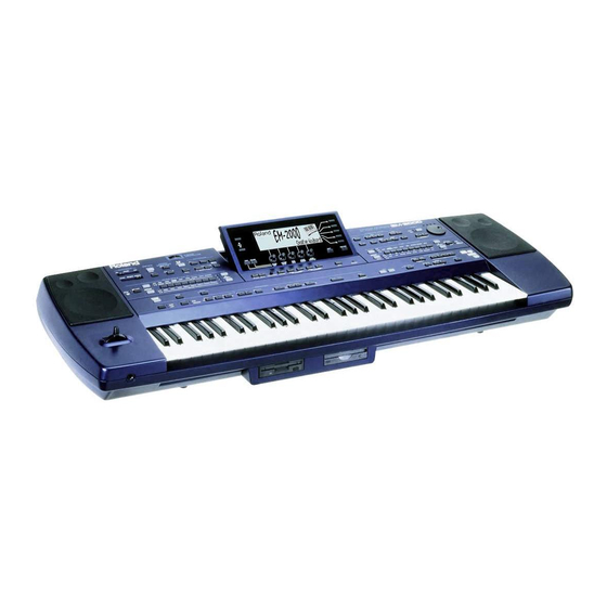
EM-2000
CREATIVE KEYBOARD
64 VOICE POLYPHONY
Table of contents
SPECIFICATIONS
DISASSEMBLY
LOCATION OF CONTROLS
EXPLODED VIEW (TOP 1/2)
EXPLODED VIEW (TOP 2/2)
PARTS LIST OF EXPLODED VIEW (BOTTOM)
EXPLODED VIEW (BOTTOM)
WIRING DIAGRAM
KEYBOARD PARTS LIST
PARTS LIST
ATTENTION WHEN YOU HAVE TO CONNECT THE SWITCHING POWER SUPPLY SWM-65
BLOCK DIAGRAM
CPU PCB ASSY
CIRCUIT DIAGRAM CPU PCB ASSY
CIRCUIT DIAGRAM CPU PCB ASSY (LCD BLOCK)
CIRCUIT DIAGRAM CPU PCB ASSY (2ND UART CONTR. BLOCK)
CIRCUIT DIAGRAM CPU PCB ASSY (D BEAM BLOCK)
CIRCUIT DIAGRAM CPU PCB ASSY (KEYSCAN BLOCK)
CIRCUIT DIAGRAM CPU PCB ASSY (MEMORY BLOCK)
CIRCUIT DIAGRAM CPU PCB ASSY (FDC & SCSI BLOCK)
XPGS PRO PCB ASSY
CIRCUIT DIAGRAM XPGS PRO PCB ASSY
AUDIO PCB ASSY & CIRCUIT DIAGRAM
D BEAM PCB ASSY & CIRCUIT DIAGRAM
EQULIZ. PCB ASSY & CIRCUIT DIAGRAM
RIGHT CONTROL PCB ASSY
CIRCUIT DIAGRAM RIGHT CONTROL PCB ASSY
LEFT CONTROL PCB ASSY
CIRCUIT DIAGRAM 1/2 LEFT CONTROL PCB ASSY
CIRCUIT DIAGRAM 2/2 LEFT CONTROL PCB ASSY
CENTRAL PCB ASSY & CIRCUIT DIAGRAM
DEBOUNCE PCB ASSY & CIRCUIT DIAGRAM
PHONES PCB ASSY & CIRCUIT DIAGRAM
INVERTER PCB ASSY & CIRCUIT DIAGRAM
AFT PCB ASSY & CIRCUIT DIAGRAM
FC7 PCB ASSY & CIRCUIT DIAGRAM
MIDI PCB ASSY & CIRCUIT DIAGRAM
POWER AMP. PCB ASSY & CIRCUIT DIAGRAM
LEFT CONTACT PCB ASSY w/RUBBER CONTACT & CIRCUIT DIAGRAM
RIGHT CONTACT PCB ASSY w/RUBBER CONTACT & CIRCUIT DIAGRAM
HOW TO SAVE / HOW TO VERSION UP
TEST MODE
SN00025
K6018341
EM-2000
SERVICE NOTES
First Edition
Issued by RES
Page
1
1
2
3
3
4
5
6
7
8/9/10
10
11
12
13
14
14
14
14
15
15
16
17
18
19
19
20
21
22
22
23
24
25
26
26
26
26
27
28
29
29
30
31/34
Printed in Italy (AD00) (AD)
1
Specifications
Keyboard
: 61 Keys, velocity sensitive with Channel Aftertouch.
Sound Source
: SC-88 Pro Like, 32 Multitimbral Parts.
Maximum polyphony
: 64 Voices
Tones
: Enhanced variation tones (1161 Top-notch sounds + 43 drum Kits including Oriental kit)
GM-GS compatible
Wave Memory
: 24MBytes.
Macro Editing
: Vib Rate, Vib Depth, Vib Delay, Cutoff Freq, Resonance, Attack Time, Decay Time, Release Time.
Music Styles
: 128 at high definition, Included 16 "Acoustic Styles" on Rom (120 Cpt/quarter note, with Pitch
Bender,: Control Change, etc..), 8 polyphonic tracks for each division.
Custom Styles
: 16 on programmable Flash Eprom (8 tracks for each style). (Memory Backup at Power -Off)
Content of ZIP Disk
: 441 Music Styles + 306 SMF Songs
Performance Memories
: 192
Midi Sets
: 8
16 Trk song sequencer
: Complete MIDI editing (Quantize, copy, erase, delete, etc...)
Built-in Effects
: Digital Reverb, Chorus, Delay, Parametric Equalizer, Insert Effects.
Hard Disk
: Internal ZIP Driver.
SCSI
: SCSI Socket for any external SCSI Devices.
Floppy Disk Drive
: HD/DD-type for SMF playback without loading. Load/Save of User Styles, Performance Memories,
Midi Set, Chord Sequences.
Display
: New Wide Graphic 240x64 pixel CCFL backlit LCD with software windows management.
Power Supply
: Direct AC (Universal Switching Power Supply).
Jack/connectors
: Stereo Phones, Output L/mono-R, Input L/Mono-R,Sustain Footswitch, Expression Pedal,
Programmable Foot Switch, External Multi switch pedal (FC7), MIDI (In, Out, Thru),
Controls
: Master Volume (Slider), Balance (Slider),LCD Contrast (Rotative), Tempo (Encoder), Part Volume
(Encoder 5pcs), Bender & Modulation (Lever).
Output (L/Mono) Level
: - 6 dBm
Master Volume at maximum
Balance at center
Reverb at zero
Chorus at zero
Select Sine Wave Tone (D31 Var.7)
Play C4 key (Velocity at maximum)
Output Impedance
: 680 Ohm
Input (L/Mono) Level
: 0 dBm
Power Amplifier at clipping
1KHz Sine Wave on External Input L/Mono
Input Impedance
: 22K Ohm
Phones Output Level
: + 8 dBm
Master Volume at maximum
Balance at center
Reverb at zero
Chorus at zero
Select Sine Wave Tone (D31Var.7)
Play C4 key (Velocity at maximum)
30 Ohm Stereo Phones
Phones Output Impedence
: 100 Ohm
Minimum Phones Impedence
: 8 Ohm
Speakers
: Two way Stereo System, in Bass Reflex boxes (2x10 cm Woofer, 2x3 cm Tweeter)
Amplification
: 20W + 20W Musical Power.
Power Consumption
: 70 W (AC 100V; AC 117V; AC 230V; AC240V)
Dimensions
: 1176 (W) X 412 (D) X 165 (H) mm
Weight
: 17 Kg
Option
: PK-5; FC-7; MSA/MSD/MSE; RH-20/80/120; DP-2; DP-6; FS-5U; EV-5; BOSS FV-300L; KC-
100/300/500
Accessories
: See " EM-2000 Parts List " on page 10.
DISASSEMBLY
Copyright © 1998 by ROLAND CORPORATION
All rights reserved. No parts of this publication may be reproduced in any form whithout the written permission of ROLAND CORPORATION.
Advertisement
Table of Contents

Related Manuals for Roland EM-2000


Summary of Contents for Roland EM-2000
-
Page 1: Specifications
: See “ EM-2000 Parts List “ on page 10. DISASSEMBLY Copyright © 1998 by ROLAND CORPORATION SN00025 K6018341 Printed in Italy (AD00) (AD) All rights reserved. No parts of this publication may be reproduced in any form whithout the written permission of ROLAND CORPORATION. -
Page 2: Location Of Controls
EM-2000 Oct, 1998 LOCATION OF CONTROLS REAR VIEW... -
Page 3: Exploded View (Top 1/2)
EM-2000 Oct, 1998 EXPLODED VIEW (TOP 1/2) -
Page 4: Exploded View (Top 2/2)
EM-2000 Oct, 1998 EXPLODED VIEW (TOP 2/2) PARTS LIST OF EXPLODED VIEW (BOTTOM) -
Page 5: Exploded View (Bottom)
EM-2000 Oct, 1998 EXPLODED VIEW (BOTTOM) -
Page 6: Wiring Diagram
EM-2000 Oct, 1998 WIRING DIAGRAM WIRING PARTS LIST 00783234 BENDER CABLE 2C P.2 7700424000 11P CABLE ASSY (12) 2C P.2 7700123000 14P CABLE ASSY 2C P2 7700425000 15P CABLE ASSY (50) 2C P.2 7695008001 16P FLAT CABLE (26) 7700426000 9P CABLE ASSY 2C P.2... - Page 7 EM-2000 Oct, 1998...
-
Page 8: Keyboard Parts List
EM-2000 Oct, 1998 PARTS LIST EM-2000 (117V/230V/230VE/240VA) = CPU Board CONSIDERATION ON PARTS ORDERING SAFETY PRECAUTIONS : KEYBOARD ASSY XPGS = XPGS PRO Board When ordering any parts listed in the parts list,please specify the following items in the order sheet. - Page 9 Oct, 1998 EM-2000 J5159114 I.C. 74 HC 14 FLAT IC10, IC11, IC12, IC13 on DEB CRYSTAL, RESONATOR 15169334 I.C. 74 LS 05 N IC1 on MIB 00894023 QUARTZ 20 MHZ MA-406 X1, X3 on CPU / X2 on XPGS 15229718RI I.C.
-
Page 10: Power Amp
EM-2000 Oct, 1998 J2289108 SELF LOCK.SCREW M3X10 TCTC H.6 Attention: J2289147 SELF LOCK.SCREW M3X12 TCTC H.6 J2289193 SELF LOCK.SCREW M3X6 TC TC H.6 when you have to connect the Switching Power Supply SWM-65 (K2458143) J2289149 SCREW 3X20 TC TFR H.7... -
Page 11: Block Diagram
EM-2000 Oct, 1998 BLOCK DIAGRAM... -
Page 12: Cpu Pcb Assy
EM-2000 Oct, 1998 CPU PCB ASSY ASSY 7700407000 Set the following switches on the Main Board as shown: View from component side... -
Page 13: Circuit Diagram (Cpu Pcb Assy)
EM-2000 Oct, 1998 CIRCUIT DIAGRAM (CPU PCB ASSY) - Page 14 Oct, 1998 EM-2000 CIRCUIT DIAGRAM LCD BLOCK/MAIN PCB ASSY CIRCUIT DIAGRAM 2ND UART CONTR./MAIN PCB ASSY CIRCUIT DIAGRAM D. BEAM BLOCK/MAIN PCB ASSY CIRCUIT DIAGRAM KEYSCAN BLOCK/MAIN PCB ASSY...
- Page 15 EM-2000 Oct, 1998 CIRCUIT DIAGRAM MEMORY BLOCK/MAIN PCB ASSY CIRCUIT DIAGRAM FDC & SCSI BLOCK/MAIN PCB ASSY...
-
Page 16: Xpgs Pro Pcb Assy
EM-2000 Oct, 1998 XPGS PRO PCB ASSY ASSY 7700102000 View from component side View from solder side... -
Page 17: Circuit Diagram (Xpgs Pro Pcb Assy)
EM-2000 Oct, 1998 CIRCUIT DIAGRAM (XPGS PRO PCB ASSY) -
Page 18: Audio Pcb Assy & Circuit Diagram
EM-2000 Oct, 1998 AUDIO PCB ASSY & CIRCUIT DIAGRAM ASSY 7700408000 View from component side... - Page 19 Oct, 1998 EM-2000 D-BEAM CONTROL PCB ASSY & CIRCUIT DIAGRAM ASSY 7700410000 View from component side EQ PCB ASSY & CIRCUIT DIAGRAM ASSY 7700409000 View from component side...
-
Page 20: Right Control Pcb Assy
EM-2000 Oct, 1998 RIGHT CONTROL PCB ASSY ASSY 7700402000 View from component side... -
Page 21: Circuit Diagram (Right Control Pcb Assy)
EM-2000 Oct, 1998 CIRCUIT DIAGRAM (RIGHT CONTROL PCB ASSY) -
Page 22: Left Control Pcb Assy
EM-2000 Oct, 1998 LEFT CONTROL PCB ASSY ASSY 7700403000 View from component side CIRCUIT DIAGRAM 1/2 (LEFT CONTROL PCB ASSY) -
Page 23: Circuit Diagram 2/2 (Left Control Pcb Assy)
EM-2000 Oct, 1998 CIRCUIT DIAGRAM 2/2 (LEFT CONTROL PCB ASSY) - Page 24 EM-2000 Oct, 1998 CENTRAL CONTROL PCB ASSY ASSY 7700404000 View from component side CIRCUIT DIAGRAM (CENTRAL CONTROL PCB ASSY)
- Page 25 EM-2000 Oct, 1998 DEBOUNCE PCB ASSY ASSY 7700406000 View from component side CIRCUIT DIAGRAM (DEBOUNCE PCB ASSY)
-
Page 26: Phones Pcb Assy & Circuit Diagram
EM-2000 Oct, 1998 PHONES PCB ASSY & CIRCUIT DIAGRAM ASSY 7627109000 View from component side INVERTER PCB ASSY & CIRCUIT DIAGRAM ASSY 7698708000 View from component side AFT PCB ASSY & CIRCUIT DIAGRAM ASSY 7700420000 View from component side FC7 PCB ASSY & CIRCUIT DIAGRAM... - Page 27 EM-2000 Oct, 1998 MIDI PCB ASSY ASSY 7700405000 View from component side CIRCUIT DIAGRAM (MIDI PCB ASSY)
- Page 28 EM-2000 Oct, 1998 AMPLIFIER PCB ASSY & CIRCUIT DIAGRAM ASSY 7700401000 View from component side...
- Page 29 EM-2000 Oct, 1998 LEFT CONTACT PCB ASSY w/RUBBER ASSY 7695005000 View from component side RIGHT CONTACT PCB ASSY w/RUBBER ASSY 7695004000 View from component side CIRCUIT DIAGRAM (LEFT CONT .PCB ASSY) CIRCUIT DIAGRAM (RIGHT CONT. PCB ASSY)
-
Page 30: How To Save / How To Version Up
To go back to the initial program, after a few seconds you have to turn the instrument off and then on again. you want to install it, you have to load the Test Program from the "Test Program EM-2000" floppy disk you've been pro- vided with. -
Page 31: Test Mode
EM-2000 TEST ENCODER Drums Part _ _> 0 - 255 Lower Num _ _> 0 - 255 EM-2000 test Ver. x . x x Style Tone Accomp Gr _ _> 0 - 255 Upper _Var _ _> 0 - 255... - Page 32 Press F5 to exit KEYSCAN Check Note: To test the external SCSI input of EM-2000, you have to connect it with an external peripheral. Press the “music style 6” button. Please notice the identifier number, which will appear on the display in place of the corresponding dash beside “Scanning Drive”.
-
Page 33: Audio Test
IN/OUT Connection THRU/IN connection AUDIO TEST While the “EM-2000 MIDI TEST” screen display is shown, connect the Midi Cables between EM-2000 and an external instrument as shown in the above diagram. Press F5 to exit Make sure that either the “OK” or the “ERROR” message appear on the display. - Page 34 Adjust the voltage output from TP 15 to 0V by using VR1. CENTER POSITION NOTE: When you adjust the voltage, be sure to keep EM-2000 in a horizontal position, and keep Then Press Upper 1 Key any object and strong light (fluorescent lamp etc.) away from around the photoreceiver.
Need help?
Do you have a question about the EM-2000 and is the answer not in the manual?
Questions and answers