
Related Manuals for Raymarine axiom pro 9 RVX


Summary of Contents for Raymarine axiom pro 9 RVX
- Page 1 Installation instructions English (en-US) Date: 10-2017 Document number: 87319-2 © 2017 Raymarine UK Limited...
- Page 3 Software updates Check the Raymarine website for the latest software releases for your product. www.raymarine.com/software Product documentation The latest versions of all English and translated documents are available to download in PDF format from the website: www.raymarine.com/manuals.
-
Page 5: Table Of Contents
Contents Chapter 1 Important information..................9 Disclaimers ..........................9 RF exposure ..........................9 Compliance Statement (Part 15.19) ..................9 FCC Interference Statement (Part 15.105 (b)) ................. 9 Industry Canada ........................10 Industry Canada (Français) ...................... 10 Japanese approvals ......................... 10 Declaration of conformity...................... - Page 6 6.5 Wi-Fi troubleshooting ....................... 62 6.6 Touchscreen troubleshooting ..................65 6.7 Miscellaneous troubleshooting ..................66 Chapter 7 Technical support..................67 7.1 Raymarine product support and servicing ..............68 Viewing product information ....................69 7.2 Learning resources ......................70 Chapter 8 Technical specification.................. 71 8.1 Axiom Pro technical specification ..................
- Page 7 1kW sonar specification ......................74 8.3 Internal GNSS (GPS / GLONASS) receiver specification ..........75 Chapter 9 Spares and accessories ................77 9.1 AXIOM Pro accessories..................... 78 Axiom transducer adaptor cables..................78 Legacy MFD adaptor plates....................78 9.2 AXIOM Pro spares......................79 9.3 RayNet to RayNet cables and connectors ..............
-
Page 9: Chapter 1 Important Information
Raymarine is not responsible for damages or injuries caused by your use or inability to use the product, by the interaction of the product with products manufactured by others, or by errors in chart data or information utilized by the product and supplied by third parties. -
Page 10: Industry Canada
Contact information: Please contact your local authorized Raymarine dealer. Declaration of conformity Raymarine UK Ltd. declares that this product is compliant with the essential requirements of R&TTE directive 1999/5/EC. The original Declaration of Conformity certificate may be viewed on the relevant product page at... -
Page 11: Product Disposal
In addition, our policy of continuous product improvement may change specifications without notice. As a result, Raymarine cannot accept liability for any differences between the product and this document. Please check the Raymarine website (www.raymarine.com) to ensure you have the most up-to-date version(s) of the documentation for your product. -
Page 13: Chapter 2 Document And Product Information
Chapter 2: Document and product information Chapter contents • 2.1 Product documentation on page 14 • 2.2 Applicable products on page 15 • 2.3 Compatible transducers — Axiom™ Pro MFDs on page 16 • 2.4 Parts supplied - Axiom Pro 9 and 12 on page 19 •... -
Page 14: Product Documentation
• Further manuals will be added to the Print Shop over the coming months for both new and legacy products. • Raymarine user manuals are also available to download free-of-charge from the Raymarine website, in the popular PDF format. These PDF files can be viewed on a PC / laptop, tablet, smartphone, or on the latest generation of Raymarine multifunction displays. -
Page 15: Applicable Products
2.2 Applicable products This document is applicable to the following products: Axiom™ Pro Multifunction Displays Product number Name Description E70371 Axiom™ Pro 9 RVX 9” MFD with built-in RealVision™ 3D and 1kW sonar module. E70481 Axiom™ Pro 9 S 9” MFD with built-in 600W sonar module. -
Page 16: Compatible Transducers - Axiom™ Pro Mfds
Axiom Pro RVX — RV connection: • RealVision™ 3D transducers. • DownVision™ transducers. • Non-CHIRP transducers can be connected using available adaptor cables. Refer to the Raymarine® website for compatible transducers: www.raymarine.com/transducers. Axiom Pro RVX — X connection: • 1kW transducers. Refer to the Raymarine® website for compatible transducers: www.raymarine.com/transducers. -
Page 17: Downvision™ Transducers
DownVision™ transducers The transducers listed below can be connected directly to DownVision™ (DV) variant MFDs. An adaptor is required for connection to RealVision™ (RV) variant MFDs. Product number Transducer Mounting Description A80351 Transom CPT-100DVS plastic (replacement for A80270 CPT-100) A80277 Thru-hull CPT-110 plastic A80271... - Page 18 Product number Transducer Mounting Description E70340 Thru-hull CPT-S 12° angled element bronze E70341 Thru-hull CPT-S 20° angled element bronze...
-
Page 19: Parts Supplied - Axiom Pro 9 And 12
2.4 Parts supplied - Axiom Pro 9 and 12 The parts listed are supplied with the following product numbers: E70371, E70481, E70372 and E70482. Axiom Pro MFD 2. Front bezel pieces and Upper keypad 3. Panel mount gasket 4. Suncover 5. -
Page 20: Parts Supplied - Axiom Pro 16
2.5 Parts supplied - Axiom Pro 16 The parts listed are supplied with the following product numbers: E70373 and E70483. Axiom Pro MFD 2. Front bezel pieces and Upper keypad 3. Panel mount gasket 4. Suncover 5. Documentation pack 6. SeaTalkng ™ to DeviceNet adaptor cable Fixings (M4 x 40 pan head bolt x 4, M4 Nylock nut x 4 and M4 washer x 4) 8. -
Page 21: Chapter 3 Installation
Chapter 3: Installation Chapter contents • 3.1 Selecting a location on page 22 • 3.2 Mounting options on page 28 • 3.3 Surface mounting on page 29 • 3.4 Bracket (trunnion) mounting on page 31 Installation... -
Page 22: Selecting A Location
This will help to keep cable runs to a minimum. EMC installation guidelines Raymarine equipment and accessories conform to the appropriate Electromagnetic Compatibility (EMC) regulations, to minimize electromagnetic interference between equipment and minimize the effect such interference could have on the performance of your system... -
Page 23: Rf Interference
For optimum EMC performance we recommend that wherever possible: • Raymarine equipment and cables connected to it are: – At least 1 m (3 ft) from any equipment transmitting or cables carrying radio signals e.g. VHF radios, cables and antennas. - Page 24 This location provides optimal GPS performance (above decks). In this location, GPS performance may be less effective. This location is NOT recommended for GPS antenna. Vessel construction The construction of your vessel can have an impact on GPS performance. For example, the proximity of heavy structures such as a structural bulkhead, or the interior of larger vessels may result in a reduced GPS signal.
-
Page 25: Touchscreen Location Requirements
Touchscreen location requirements Touchscreens offer an alternative to using physical buttons to control your display. Full product functionality can be achieved using the Touchscreen. Note: Touchscreen performance can be affected by the installation environment, specifically Touchscreen displays installed above decks, where it will be open to the elements may exhibit the following: •... -
Page 26: Viewing Angle Considerations
Viewing angle considerations As display contrast and color are affected by the viewing angle, It is recommended that you temporarily power up the display, prior to installation, to enable you to best judge which location provides the optimum viewing angle. Refer to Chapter 8 Technical specification for viewing angles for your product. - Page 27 Axiom Pro 16 dimensions 452.02 mm (17.8 in) 258 mm (10.16 in) 33.4 mm (1.31 in) 68.4 mm (2.69 in) 138.6 mm (5.46 in) straight connector 118.6 mm (4.67 in) right angled connector 15.2 mm (0.6 in) 207 mm (8.15 in) straight connector 187 mm (7.36 in) right angled connector Installation...
-
Page 28: Mounting Options
3.2 Mounting options Axiom Pro 9, 12, and 16 can be surface mounted. The Axiom Pro 9 and 12 can also be bracket mounted on a trunnion. Legacy MFD adaptor plates are also available to enable you to easily swap out older MFDs for new Axiom Pro MFDs, please refer to Chapter 9 Spares and accessories for a list of available adaptors. -
Page 29: Surface Mounting
3.3 Surface mounting The MFD can be surface mounted. Before mounting the unit, ensure that you have: • Selected a suitable location. • Identified the cable connections and route that the cables will take. • Detached the Menu/Home buttons keypad. •... -
Page 30: Fitting The Menu-Home Button
Fitting the Menu-Home button Follow the steps below to fit the Menu/Home button. 1. Slide the backing plate behind the locating tabs as shown below. Removing the bezel pieces If you need to remove the MFD once installed then the bezel pieces will need to be removed to gain access to the fixings. -
Page 31: Bracket (Trunnion) Mounting
3.4 Bracket (trunnion) mounting Axiom Pro 9 and 12 MFDs can be mounted on the supplied trunnion bracket. The bracket can be used to mount your MFD on a horizontal surface. Ensure you have chosen a suitable mounting location for your MFD, with sufficient head room to allow the MFD’s angle to be adjusted or the MFD to be removed if necessary. -
Page 33: Chapter 4 Connections
Chapter 4: Connections Chapter contents • 4.1 Connections overview on page 34 • 4.2 Power connection on page 37 • 4.3 NMEA 2000 (SeaTalkng ®) connection on page 42 • 4.4 NMEA 0183 connection on page 43 • 4.5 Transducer connection on page 44 •... -
Page 34: Connections Overview
4.1 Connections overview Axiom Pro connection options Connector Connector Connects to: Suitable cables GA150 connection GA150 antenna GA150’s fitted cable NMEA 2000 • SeaTalkng ® • SeaTalkng ® to connection backbone DeviceNet adaptor cable • NMEA 2000 backbone • DeviceNet cables Network connection (x RayNet network or RayNet cable with... - Page 35 Connector Connector Connects to: Suitable cables Power / Video out / 12/24 V DC power Power/Video/0183 NMEA 0183 connection supply / Video input / cable NMEA 0183 Optional grounding Vessel RF ground, Refer to Grounding point or negative battery — optional dedicated terminal drain wire section for...
-
Page 36: Connecting Cables
Axiom Pro S — transducer connection options Connector Connects to: Suitable cables CPT-S transducers via adaptor • Adaptor cables cables. Note: Refer to Chapter 9 Spares and Accessories for available cables. Connecting cables Follow the steps below to connect the cable(s) to your product. 1. -
Page 37: Power Connection
• The suitable fuse rating for the thermal breaker is dependent on the number of devices you are connecting. If in doubt consult an authorized Raymarine dealer. • Your product’s power cable may have fitted in-line fuse, if not then you can add an in-line fuse to the positive wire of your products power connection. - Page 38 The information provided below is for guidance only, to help protect your product. It covers common vessel power arrangements, but does NOT cover every scenario. If you are unsure how to provide the correct level of protection, please consult an authorized Raymarine dealer or a suitably qualified professional marine electrician.
- Page 39 Implementation — connection to distribution panel • Alternatively, the supplied power cable may be connected to a suitable breaker or switch on the vessel's distribution panel or factory-fitted power distribution point. • The distribution point should be fed from the vessel’s primary power source by 8 AWG (8.36 mm cable.
- Page 40 Important: Be aware that the suitable fuse rating for the thermal breaker or fuse is dependent on the number of devices you are connecting. Power cable extension If you need to extend the length of the power cable supplied with your product, ensure you observe the following advice: •...
-
Page 41: Grounding - Optional Dedicated Drain Wire
Grounding — optional dedicated drain wire Frequencies emitted from equipment such as switch mode power supplies or MF/HF transmitters etc. can cause interference with your MFD’s touchscreen. If you experience issues with touchscreen performance, fitting an additional dedicated drain wire can resolve the issue. Note: The additional wire supplements the drain wire (shield) that is part of the product’s power cable and should ONLY be used when touchscreen interference is observed. -
Page 42: Nmea 2000 (Seatalkng ®) Connection
4.3 NMEA 2000 (SeaTalkng ®) connection The MFD can transmit and receive data from devices connected on a compliant CAN bus network. The MFD is connected to the backbone using the MFD’s NMEA 2000 connector. Use the supplied DeviceNet to SeaTalkng ® adaptor cable to connect your MFD to a SeaTalkng ® backbone. -
Page 43: Nmea 0183 Connection
4.4 NMEA 0183 connection NMEA 0183 devices can be connected to your MFD using the NMEA 0183 wires on the supplied Power/Video/NMEA 0183 cable. 2 NMEA 0183 ports are available: • Port 1: Input and output 4,800 or 38,400 baud rate. •... -
Page 44: Transducer Connection
4.5 Transducer connection If your MFD includes a built-in sonar module then you can connect a transducer to your MFD. • Axiom Pro RVX: – 1 x 25 pin connector — connect to RealVision™ 3D transducers – 1 x 11 pin connector — connect to 1kW transducers. •... - Page 45 A80490 Axiom RV to 9-pin DV Transducer Adapter A80491 Axiom RV to 25-pin RV & 7-pin Embedded Transducers Y-Cable A80492 Axiom RV to 25-pin RV & 7-pin CP370 Transducers Y-Cable A80493 Axiom RV to 7-pin Embedded & 9-pin DV Transducers Y-Cable A80494 Axiom RV to 7-pin CP370 &...
-
Page 46: Network Connection
4.6 Network connection Your MFD can be directly connected to a compatible product using the RayNet network connection. Your MFD can also be connected to a network of products when using a suitable network switch. RayNet to RayNet cable — Connect one end of the RayNet cable to your MFD and the opposite end to a RayNet device or RayNet network switch. -
Page 47: Ga150 Connection
4.7 GA150 connection The GA150 (A80288) can be used to improve your MFD’s GNSS receiver’s reception. For installation details, refer to the documentation provided with your GA150. Connections... -
Page 48: Accessory Connection
4.8 Accessory connection The RCR-SDUSB or RCR-2 can be connected to your MFD using the Accessory connection. The RCR-SDUSB accessory can provide your MFD with extra storage by connecting external storage devices i.e.: • SD card (or MicroSD card when using a SD card adaptor) •... -
Page 49: Analog Video Connection
4.9 Analog video connection Analog video sources such as a Thermal or security camera can be connected to your MFD using the BNC connector on the supplied Power/Video/NMEA 0183 cable. Power/Video/NMEA 0183 cable supplied with your MFD. 2. Analog video device. 3. -
Page 51: Chapter 5 Maintaining Your Display
Chapter 5: Maintaining your display Chapter contents • 5.1 Service and maintenance on page 52 • 5.2 Product cleaning on page 53 Maintaining your display... -
Page 52: Service And Maintenance
Warning: FCC Warning (Part 15.21) Changes or modifications to this equipment not expressly approved in writing by Raymarine Incorporated could violate compliance with FCC rules and void the user’s authority to operate the equipment. Caution: Sun covers • If your product is supplied with a sun cover, to protect against the damaging effects of ultraviolet (UV) light, always fit the sun cover when the product is not in use. -
Page 53: Product Cleaning
5.2 Product cleaning Best cleaning practices. When cleaning products: • Lightly rinse or flush with clean, cool fresh water. • If your product has a display screen, do NOT wipe the screen with a dry cloth, as this could scratch the screen coating. •... - Page 55 Chapter 6: Troubleshooting Chapter contents • 6.1 Troubleshooting on page 56 • 6.2 Power up troubleshooting on page 57 • 6.3 GNSS troubleshooting on page 58 • 6.4 Sonar troubleshooting on page 59 • 6.5 Wi-Fi troubleshooting on page 62 •...
- Page 56 If after referring to this section you are still having problems with your product, please refer to the Technical support section of this manual for useful links and Raymarine Product Support contact details.
-
Page 57: Chapter 6 Troubleshooting
In the unlikely event that the product’s software has become corrupted, try downloading and installing the latest software from the Raymarine website. 2. On display products, as a last resort, attempt to perform a ‘Power on Reset’. Be aware that this will delete all settings / presets and user data (such as waypoints and tracks), and revert the unit back to factory defaults. -
Page 58: Gnss Troubleshooting
6.3 GNSS troubleshooting Problems with the GNSS and their possible causes and solutions are described here. Problem Possible causes Possible solutions “No Fix” GNSS status Geographic location or Check periodically to see if a fix is obtained icon is displayed. prevailing conditions in better conditions or another geographic preventing satellite fix. -
Page 59: Sonar Troubleshooting
External sonar module: • Check that the unit is correctly connected to the SeaTalkhs ™ / RayNet network multifunction display or Raymarine network switch. If a problem. crossover coupler or other coupler cable / adapter is used, check all connections ensuring connections are secure, clean and free from corrosion, replace if necessary. - Page 60 Possible causes Possible solutions Damaged cables Check the unit’s connector for broken or bent pins. 2. Check that the cable connector is fully inserted into the unit and that the locking collar is in the locked position. 3. Check the cable and connectors for signs of damage or corrosion, replace if necessary.
- Page 61 Possible causes Possible solutions Transducer location • Check that the transducer has been installed in accordance with the instructions provided with the transducer. • If a transom mount transducer is mounted too high on the transom it may be lifting out of the water, check that the transducer face is fully submerged when planing and turning.
-
Page 62: Wi-Fi Troubleshooting
6.5 Wi-Fi troubleshooting Before troubleshooting problems with your Wi-Fi connection, ensure that you have followed the Wi-Fi location requirements guidance provided in the relevant installation instructions and performed a power cycle/reboot of the devices you are experiencing problems with. Cannot find network Possible cause Possible solutions Wi-Fi not currently enabled on devices. - Page 63 Possible cause Possible solutions Interference caused by other devices that use Temporarily switch off each device in turn until the 2.4GHz frequency See list below of some you have identified the device causing the common devices that use the 2.4GHz frequency: interference, then remove or reposition the offending device(s).
- Page 64 Mobile application running slowly or not at all Possible cause Possible solutions Raymarine app not installed Install mobile app from relevant app store. Raymarine app version not compatible with MFD Ensure mobile app and MFD software are latest software available versions. Mobile apps not enabled on MFD Enable “Viewing only”...
-
Page 65: Touchscreen Troubleshooting
6.6 Touchscreen troubleshooting Problems with the touchscreen and their possible causes and solutions are described here. Problem Possible causes Possible solutions Touchscreen does not TouchLock is enabled. Swipe your finger from left to right across the operate as expected. Power button swipe area to de-activate the TouchLock. -
Page 66: Miscellaneous Troubleshooting
Check that the power source is of the correct • System crashes or voltage and sufficient current. other erratic behavior. Software mismatch Go to www.raymarine.com and click on on system (upgrade support for the latest software downloads. required). Corrupt data / other Perform a factory reset. -
Page 67: Chapter 7 Technical Support
Chapter 7: Technical support Chapter contents • 7.1 Raymarine product support and servicing on page 68 • 7.2 Learning resources on page 70 Technical support... -
Page 68: Raymarine Product Support And Servicing
You can obtain this product information using the menus within your product. Servicing and warranty Raymarine offers dedicated service departments for warranty, service, and repairs. Don’t forget to visit the Raymarine website to register your product for extended warranty benefits: http://www.raymarine.co.uk/display/?id=788. Telephone... -
Page 69: Viewing Product Information
Denmark +45 437 164 64 support.dk@raymarine.com (Raymarine subsidiary) Russia +7 495 788 info@mikstmarine.ru 0508 (Authorized Raymarine distributor) Viewing product information The Getting started tab contains hardware and software information for your MFD. 1. Select Settings, from the Homescreen. Technical support... -
Page 70: Learning Resources
7.2 Learning resources Raymarine has produced a range of learning resources to help you get the most out of your products. Video tutorials Raymarine official channel on YouTube: • http://www.youtube.com/user/RaymarineInc Video Gallery: • http://www.raymarine.co.uk/view/?id=2679 Product Support videos: • http://www.raymarine.co.uk/view/?id=4952 Note: •... -
Page 71: Chapter 8 Technical Specification
Chapter 8: Technical specification Chapter contents • 8.1 Axiom Pro technical specification on page 72 • 8.2 Internal sonar specification on page 74 • 8.3 Internal GNSS (GPS / GLONASS) receiver specification on page 75 Technical specification... -
Page 72: Axiom Pro Technical Specification
8.1 Axiom Pro technical specification Power Axiom™ Pro 9 Axiom™ Pro 12 Axiom™ Pro 16 Nominal supply voltage 12/24 V dc Operating voltage 8 V dc to 32V dc range Fuse requirements • Inline fuse = 15 Amp, or • Thermal breaker = 15 Amp Maximum current Environmental Axiom™... - Page 73 Axiom™ Pro 9 Axiom™ Pro 12 Axiom™ Pro 16 Accessory 1 x USB Micro B connection Network 2 x RayNet type SeaTalkhs ™ connector 10/100 Mbits/s Wi-Fi 802.11/b/g/n Bluetooth Bluetooth V4.0 Storage Axiom™ Pro 9 Axiom™ Pro 12 Axiom™ Pro 16 Internal 16 GB Solid State (14 GB usable) MicroSD card reader...
-
Page 74: Internal Sonar Specification
8.2 Internal sonar specification RealVision™ 3D sonar specification The following specification only applies to RealVision™ 3D products. Channels Channels • 1 x CHIRP sonar • 1 x DownVision™ • 1 x SideVision™ • 1 x RealVision™ 3D Range • CHIRP sonar = 0.6 M (2 ft) to 274 m (900 ft) •... -
Page 75: Internal Gnss (Gps / Glonass) Receiver Specification
8.3 Internal GNSS (GPS / GLONASS) receiver specification Channels Multiple — ability to simultaneously track up to 28 satellites Cold start <2 minutes Receiver IC Sensitivity • 165 dBm (Tracking) • 160 dBm (Acquisition) • 148 dBm (Cold start) • GPS GNSS compatibility •... -
Page 77: Chapter 9 Spares And Accessories
Chapter 9: Spares and accessories Chapter contents • 9.1 AXIOM Pro accessories on page 78 • 9.2 AXIOM Pro spares on page 79 • 9.3 RayNet to RayNet cables and connectors on page 80 • 9.4 SeaTalk cables and accessories on page 83 ng®... -
Page 78: Axiom Pro Accessories
9.1 AXIOM Pro accessories Part numbers Item Axiom™ Pro 9 Axiom™ Pro 12 Axiom™ Pro 16 RCR-SDUSB — External A80440 MicroSD and USB reader RMK-10 — MFD remote control A80438 / T70293 GA150 A80288 Suncover A80534 A80535 A80536 Axiom Pro Bracket/Ball mount A80537 plate Right angled RV transducer... -
Page 79: Axiom Pro Spares
9.2 AXIOM Pro spares Part numbers Item Axiom™ Pro 9 Axiom™ Pro 12 Axiom™ Pro 16 Power/Video/NMEA 0183 cable R62379 1.5 m (4.9 ft) Angled Power/Video/NMEA R70029 0183 cable 1.5 m (4.9 ft) with right angled connector Keypad assembly R70600 Trim kit —... -
Page 80: Raynet To Raynet Cables And Connectors
9.3 RayNet to RayNet cables and connectors Description Typical use Quantity Standard RayNet connection Suitable for connecting all RayNet equipment cable with a RayNet (female) directly to LightHouse multifunction displays socket on both ends. featuring a RayNet connector. Can also be used to connect RayNet equipment via a RayNet network switch (e.g. -
Page 81: Raynet To Rj45 Adapter Cables
Connect a legacy G-Series GPM-400, C-Series (male) plug on one end, Widescreen or E-Series Widescreen MFD to and an RJ45 SeaTalk a Raymarine radar scanner supplied with a waterproof (male) plug on RayNet power / data cable. the other end. - Page 82 (E55060 or R32142) to connect Raymarine products with an RJ45 connection (e.g. radar scanner, thermal camera or DSM300) to a LightHouse MFD or RayNet network switch (e.g. the HS5).
-
Page 83: Seatalk Ng® Cables And Accessories
9.4 SeaTalk cables and accessories ng® SeaTalk cables and accessories for use with compatible products. Part No Description Notes Includes: T70134 SeaTalk starter kit • 1 x 5 Way connector (A06064) • 2 x Backbone terminator (A06031) • 1 x 3 m (9.8 ft) spur cable (A06040) •... - Page 84 Part No Description Notes A06032 SeaTalk Blanking plug R12112 ACU / SPX SeaTalk spur Connects an SPX course computer or an cable 0.3 m (1.0 ft) ACU to a SeaTalk backbone. A06047 SeaTalk (3 pin) to SeaTalk adaptor cable 0.4 m (1.3 ft) A22164 SeaTalk to SeaTalk spur 1 m...
- Page 85 Index Legacy adaptor............14 LightHouse 3 ............14 Location requirements Axiom™ Pro MFDs ............ 15 General ..............22 GPS ..............23 Touchscreen ............25 Viewing angle ............26 CHIRP transducers ........... 17 Wi-Fi..............25 Cleaning ..............53 Compass safe distance ...........23 Conical beam transducers........17 Connecting cables...........36 Maintenance............52 Connection Mounting surface requirements ......22 Accessory ............48...
- Page 88 Raymarine Marine House, Cartwright Drive, Fareham, Hampshire. PO15 5RJ. United Kingdom. Tel: +44 (0)1329 246 700 www.raymarine.com a brand by...
- Page 89 Basic operation instructions English (en-US) Date: 09-2017 Document number: 81369-4 © 2017 Raymarine UK Limited...
- Page 90 Important information about this document This document provides an introduction to using your Raymarine multifunction display, covering only basic operations. To obtain the complete “LightHouse 3 Advanced operations” document, visit the Raymarine website. The document is available in 2 di erent formats: 1.
- Page 91 Contents Chapter 1 Important information ..........8 Disclaimers ................8 Chapter 2 Set up ................
- Page 92 3.8 Alarms................29 3.9 Satellite navigation / positioning.
- Page 93 11.1 Raymarine mobile apps ........
-
Page 94: Chapter 1 Important Information
Raymarine product. Disclaimers Raymarine does not warrant that this product is error-free or that it is compatible with products manufactured by any person or entity other than Raymarine. This product uses digital chart data, and electronic information from Global Navigation Satellite Systems (GNSS) which may contain errors. -
Page 95: Chapter 2 Set Up
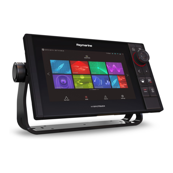
Chapter 2: Set up 2.1 Getting started Controls — Axiom variants Touchscreen Power button MicroSD card MicroSD card reader (9” & reader (7” display 12” displays) only) Powering on the display When power is available to the MFD but the MFD is switched off, the Power symbol will be illuminated. -
Page 96: Controls - Axiom Pro Variants
Powering off the display 1. Swipe your finger from left to right across the Power button swipe area. The Shortcuts menu is displayed. 2. Press and hold the Power symbol until the screen switches off. Note: When powered off, the unit may still draw a small amount of power from the battery, if this is a concern unplug the power supply or switch off at the breaker. -
Page 97: First Power Up Data Master Selection
Touchscreen — The touchscreen can be used to control the MFD. 2. Home — Press to display the Homescreen. 3. Menu — Press to open or close menus. 4. Uni-controller — The Uni-controller consists of a center OK button, Directional controls and a Rotary knob. 5. -
Page 98: Startup Wizard
You can change your Data master at anytime by selecting Assign as Data master against a MFD listed in the Network tab of the Settings menu: Homescreen > Settings > Network. Startup wizard If the MFD is being installed as a stand alone installation or as part of a new system, then the first time the MFD is powered up the Startup wizard will be displayed. -
Page 99: Data Sources Menu
Data sources menu When a system includes multiple sources of a data type, such as depth data, the system will choose the most appropriate source for the data. If you prefer, you can manually select your own data source. The Data sources menu can be accessed on your Data master MFD, from the Settings menu: Homescreen >... -
Page 100: Configuring Transducer Settings
Configuring Transducer settings For systems set up with Sonar, you should configure your transducer settings. 1. Select Transducer from the Sonar app’s Settings menu: Menu > Settings > Transducer 2. Select how you want your depth to appear: i. Below transducer (default) — No offset required ii. -
Page 101: Performing A Settings Or Factory Reset
You can also assign a function to the User Programmable Button from the Settings menu: Homescreen > Settings > This Display > User Configurable Key. Performing a settings or factory reset Performing a Factory reset will erase ALL user data and reset the MFD’s settings to Factory default values. -
Page 102: Activating Touchlock
Activating touchlock In rough weather conditions precipitation may lead to erroneous touches being detected by the touchscreen. In these conditions you can use touchlock to prevent this. 1. Select Activate touchlock from the Shortcuts menu. With touchlock activated the touchscreen will be disabled. To re-enable the touchscreen, swipe from left to right across the Power button swipe area. -
Page 103: Removing Microsd Card From Its Adaptor
Native card supported Type Size format Format Up to 4GB FAT12, NTFS, MicroSDSC (Micro FAT16 or FAT32 Secure Digital FAT16B Standard Capacity) MicroSDHC (Micro 4GB to 32GB FAT32 NTFS, Secure Digital High FAT32 Capacity) MicroSDXC (Micro 32GB to 2TB exFAT NTFS, Secure Digital FAT32... -
Page 104: Inserting A Microsd Card - Axiom Pro Variants
1. Pull back the microSD card reader cover as shown above. 2. Insert your microSD card with the contacts facing down. 3. Close the cover and ensure it is seated correctly. Removing a MicroSD card 1. Select Eject SD card from the Import/export page: Homescreen > My data >... -
Page 105: Software Updates
Raymarine® regularly issues software updates for its products which provide new and enhanced features and improved performance and usability. You should ensure that you have the latest software for your products by regularly checking the Raymarine® website for new software releases. www.raymarine.com/software... -
Page 106: Updating Software Using A Memory Card
1. Check the software version of your product. Refer to the documentation supplied with your product for information on checking software version. 2. Check the latest available software on the Raymarine website: (www.raymarine.com > Support > Software Updates). 3. Download the software package. - Page 107 3. To set up a Wi-Fi connection select Wi-Fi settings and connect to the required Wi-Fi access point/hotspot. 4. Select Start and then follow any onscreen instructions.
-
Page 108: Chapter 3 Homescreen
Chapter 3: Homescreen 3.1 Accepting the Limitations on Use After your MFD has powered up the Homescreen is displayed. 1. Before using the MFD you must accept the Limitations on Use (LoU) disclaimer. To view the full LoU Disclaimer, select ‘more details’. The LoU acknowledgment is displayed each time the display is powered on and for each new user profile. -
Page 109: Homescreen Overview
3.2 Homescreen overview All settings and apps can be accessed from the Homescreen. GNSS position/fix details — Select the area to view fix accuracy and access GNSS settings. 2. Profile — Select the area to change the profile in use or to create, edit or delete profiles. -
Page 110: User Profiles
You can Customize, Rename or Delete app pages from the pop-over options. 2. Select Customize from the pop-over options to change page layout and apps used. To Create a new page press and hold on a blank space on the Homescreen. 3. -
Page 111: My Data
Selecting the Plus (+) icon will create a new profile based on the profile that is currently in use. MFD settings changes are unique to the profile in use and are retained the next time the profile is used. The distance and time that a profile has been active is displayed for each profile. -
Page 112: Settings
Selecting Waypoints, Routes or Tracks will take you to the relevant list where you can manage and customize your data. Selecting Trip will display the trip counters. Selecting Reset man. trip will reset the Trip counter to zero. Selecting Files opens a file browser. Selecting Import/export allows you to back up or restore User data using external storage. - Page 113 Options • Configure fuel tanks. • Configure preferred units of measurement. Units • Configure Bearing mode. • Configure variation. • Configure GNSS system datum. • Assign a Homescreen page or app to start on This display power up. • Select save location for screenshots. •...
-
Page 114: Man Overboard (Mob)
3.7 Man Overboard (MOB) If a person or object falls overboard, you can use the Man Overboard (MOB) feature to mark the position that your vessel was at when the MOB alarm was activated. The MOB feature can be activated by pressing and holding on the MOB icon: on the Homescreen or the waypoint/MOB icon: found at the top of all apps. -
Page 115: Alarms
3.8 Alarms The Alarm manager can be accessed from the Homescreen. Example: Active alarms list Alarms are raised by system functions, and also external equipment connected to your display. When an Alarm is triggered all networked MFDs will display audible and visual warnings. -
Page 116: Satellite Navigation / Positioning
3.9 Satellite navigation / positioning GNSS Status Your vessel’s GNSS position is provided in the top left corner of the Homescreen. You can access fix accuracy and settings by selecting the area. If latitude and longitude is displayed on the Homescreen then you have a valid position fix. -
Page 117: Gnss Settings
GNSS Settings The settings for your GNSS receiver (internal or external) can be accessed from the Satellites menu: Homescreen > GNSS pop-over > Satellites > Settings. From the GNSS Settings tab you can: • activate and deactivate use of Differential positioning (SBAS) •... -
Page 118: Sidebar
Status area icons The status of connected AIS, Radars Sonars/Transducers are reported in the Status area: pop-over menu options From the Options pop-over you can adjust the Time offset from UTC. 3.11 Sidebar The Sidebar is available in all apps and provides quick access to system data. -
Page 119: Data Overlays
3.12 Data overlays System data can be overlaid onto the Chart app, Radar app, Sonar app and Camera app. Some apps have Data overlays enabled by default. Data overlays can be placed anywhere on the app page and can be placed over any app in a Splitscreen app page. -
Page 120: Connecting To A Wireless Display
With a Splitscreen app page displayed: 1. Select Edit split ratio from the Page settings tab: Menu > Settings > Page settings > Edit split ratio. 2. Drag the Resize icon to create the desired split ratio. 3. Select Save. 3.14 Connecting to a wireless display Your MFD can be connected to a wireless display using an external dongle or a display that has built-in support. - Page 121 Note: Don’t forget to check your wireless display for any required confirmations/acknowledgements. 2. Some non Miracast certified devices may not be able to connect with Wi-Fi Sharing enabled, in this case disable Wi-Fi Sharing and try again. 3. If you experience issues connecting try disabling and enabling the wireless display feature on your display and MFD or power cycle both devices.
-
Page 122: Chapter 4 Autopilot Control
Chapter 4: Autopilot control 4.1 Autopilot control Your MFD can be integrated with an Evolution autopilot system and act as the autopilot’s controller. Please refer to the documentation supplied with your autopilot for details on installing and connecting your autopilot to your MFD. Autopilot control from your MFD can be enabled and disabled from the Autopilot tab in the Settings menu: Homescreen >... -
Page 123: Engaging The Autopilot - Navigation
4. Select Engage pilot. Engaging the autopilot — Navigation With Autopilot control enabled: 1. For Wheel and Tiller pilots, engage the mechanical drive by either engaging the wheel drive’s clutch or attaching the pushrod onto the tiller pin. 2. Initiate a Goto or Follow from the chart app. 3. -
Page 124: Chapter 5 Chart App
Chapter 5: Chart app 5.1 Chart app overview The Chart app displays a representation of your vessel in relation to land masses and other charted objects, which enables you to plan and navigate to your desired destination. The Chart app requires a GNSS position fix in order to display your vessel at the correct location on a world map. -
Page 125: Chart App Controls
Route Destination waypoint You can plan your route in During a goto, this is advance by creating a Route the current destination using Waypoints to mark waypoint. each route leg. Heading line COG line If Heading data is available If COG data is available then a Heading vector then you can display for your vessel can be... -
Page 126: Chart Ranging And Panning
Icon Description Action Range In Decreases the range/distance displayed onscreen. Range Out Increases the range/distance displayed onscreen. Chart ranging and panning You can change the range displayed in the Chart app using the onscreen Range controls or by using the pinch-to-zoom multi-touch gesture. -
Page 127: Chart Modes
You may choose a different chart for each instance of the Chart app, accessed from the Homescreen. Cartography selection will persist until changed. Chart modes The Chart app provides preset modes that can be used to quickly set up the Chart app for your intended use. To change Chart mode select the required mode from the app menu. - Page 128 From the Vessel details pop-over you can: • start/stop a track. • offset the position of the vessel symbol. • change the symbol used to represent your vessel. • set the length of vessel vectors. • show / hide Heading and COG vectors. •...
-
Page 129: Layers
Layers Layers are available that can overlaid on the Chart app. Layers include Aerial photographs, AIS targets, Radar image, Range rings, Tide graphs, and Crowd sourced content. The Layers tab from the Chart app Settings menu: Menu > Settings > Layers provides controls for Chart layers. -
Page 130: Placing A Waypoint
Chart motion Chart motion controls how the chart and boat are drawn to keep the boat onscreen as you move. Chart orientation The orientation of the chart affects the alignment of the chart relative to your vessel, route or North. Boat position Adjust the boat position to allow more or less ‘look ahead’... -
Page 131: Navigating To A Waypoint Or Point Of Interest
Navigating to a waypoint or point of interest You can perform a “Goto” to a Waypoint or specific location. 1. Select and hold on the waypoint or point of interest and select Goto from the context menu. You can stop the Goto at any time by selecting and holding anywhere in the Chart app and choosing Stop, or selecting another Goto. -
Page 132: Creating A Route
Creating a Route 1. Select and hold on the location for the first waypoint. 2. Select Build route from the context menu. 3. Select the location for the second waypoint. The 2 waypoints will be joined by a line, creating the first leg of your route. -
Page 133: Autorouting
Autorouting Autorouting is available when using compatible cartography. Autorouting allows you to build a route automatically between a point on the chart and your vessel. You can select any point on the Chart and from the Chart context menu select Autoroute to here or you can select Autoroute to from an existing waypoint’s context menu to create a route automatically between your vessel and the chosen point. -
Page 134: Following A Route
Following a Route You can follow a saved route. With the Route displayed in the Chart app: 1. Select and hold on a Route leg within the Route you want to follow. 2. Select Follow Route from the Route context menu. Creating a track You can record your vessel’s journey using Tracks. -
Page 135: Chapter 6 Sonar App
Chapter 6: Sonar app 6.1 Sonar app overview The Sonar app displays a visualization of the echoes received from a Sonar module and transducer. The Sonar app is compatible with Traditional, CHIRP, DownVision™, SideVision™ and RealVision™ 3D sonar modules and transducers. The Sonar app builds an underwater view of bottom structure and targets in the water column. -
Page 136: Realvision 3D Controls
Icon Description Action Pilot icon Opens and closes the Pilot Sidebar Menu icon Opens the app menu Image Displays onscreen sensitivity / image adjustment adjustment controls Pause Pause RealVision™ 3D sonar image. Unpause When the Sonar app is paused, you can recommence scrolling by selecting the Unpause icon. -
Page 137: Opening The Sonar App
Homescreen that includes a Sonar app. Pre-requisites: Ensure your Sonar module is compatible (check the latest details available on the Raymarine website). If in doubt please contact an authorized Raymarine dealer for advice. 2. Ensure you have installed your Sonar module in accordance with the documentation that was supplied with the module. - Page 138 Please select a sonar channel The first time you open a new app page that includes the Sonar app you will need to select a Sonar channel. Select OK and then choose the Sonar channel you want to use from the list: Sonar on and pinging If your Sonar app has already been set up then when the Sonar app is...
- Page 139 No sonar source available If the ’No sonar source available’ warning is displayed then either: • your sonar module is still powering up. • your MFD cannot establish a connection with your external Sonar module • your Internal Sonar module has no transducer connected. Check your external sonar module’s network and power connection, check your MFD’s network or transducer connection ensuring the connections and cabling is correct and free from damage, then...
-
Page 140: Selecting A Sonar Channel
Check your transducer connection(s) are correct and free from damage, then power cycle your system. If the transducer is still not found then refer to your equipment’s installation documentation for further troubleshooting information. Selecting a Sonar channel The first time you open a new Sonar app page you will be requested to select a channel, subsequently you can change the sonar channel by selecting a channel icon from the Sonar app menu. -
Page 141: Placing A Waypoint (Sonar, Downvision And Sidevision)
Placing a Waypoint (Sonar, DownVision and SideVision) When you observe something of interest in the Sonar app you can place a waypoint at its location so that you can find the area again. 1. Select and hold on the point of interest onscreen. The Context menu is displayed and scrolling is paused, temporarily. -
Page 142: Sonar Scroll Back
3. Select Move position to adjust the marker’s position before creating the waypoint. You can move the waypoint along its current axis by sliding 1 finger across the screen. You can also adjust the view onscreen using the usual 2 finger touch gestures. 4. - Page 143 Unpause — Selecting this option resumes live sonar scrolling. 2. Scroll back bar — Use this to move back and forward through the available sonar history. You can either drag the position indicator right or left or select a specific location on the bar to jump to that position.
-
Page 144: Chapter 7 Radar App
Chapter 7: Radar app 7.1 Radar app overview The Radar app displays a visualization of the echoes received from a connected Radar scanner. The Radar app is an aid used to help enhance collision and situational awareness by enabling target’s distance and speed to be tracked in relation to your vessel. -
Page 145: Opening The Radar App
Homescreen that includes the Radar app. Pre-requisites: Ensure your Radar scanner is compatible, check the latest details available on the Raymarine website, if in doubt please contact an authorized Raymarine dealer for advice. 2. Ensure you have installed your Radar scanner in accordance with the documentation that was supplied with your Radar. - Page 146 Off/Not Connected If the ‘Off/Not Connected’ message is displayed then: • your Radar scanner may be powered down, or • your MFD cannot establish a connection with your Radar scanner Select On to power up your Radar. If the ‘Radar not found’ message is displayed then a connection could not be established, ensure that network and power connections to your Radar and MFD are correct and free from damage and then power cycle your system.
-
Page 147: Selecting A Radar Scanner
Transmitting If your Radar scanner is connected, powered up and transmitting then the Radar image is displayed and echoes/targets are displayed onscreen. Selecting a Radar scanner On systems with 2 Radar scanners, you can select which Radar scanner is used in each instance of the Radar app. 1. -
Page 148: Radar Modes
3. Select the Radar scanner that you want to associate with the current instance of the Radar app. 4. Close the Settings page. The current instance of the Radar app will change to display the selected Radar scanner. Radar scanner selection shall persist over a power cycle. - Page 149 OFFSHORE Offshore mode takes into account high levels of Sea clutter so that targets are still visible, useful when navigating in open water away from the coast. Radar scanners: All. BIRD Bird mode optimizes the display to help identify flocks of birds, useful when trying to locate a fishing area.
-
Page 150: Chapter 8 Dashboard App
Chapter 8: Dashboard app 8.1 Dashboard app overview The Dashboard app enables you to view system data. System data may be generated by your MFD or by devices connected to your MFD via SeaTalkng ® / NMEA 2000 and SeaTalkhs ™. The Dashboard app can also be configured to provide control of your compatible Digital Switching devices. -
Page 151: Switching Data Page
Icon Description Function Pilot icon Opens and closes the Pilot Sidebar Menu icon Opens the app menu. Left arrow Displays the previous data page. Right arrow Displays the next data page. Switching data page 1. Use the Left arrow and Right arrow buttons, located at the bottom of the screen, to cycle through the available data pages. -
Page 152: Chapter 9 Camera App
Chapter 9: Camera app 9.1 Camera app overview IP (Internet Protocol) video feeds and analog camera feeds available via an Axiom™ Pro MFD can be viewed, recorded and played back using the Camera app. Examples of video feeds include: CCTV cameras and Thermal imaging cameras. -
Page 153: Opening The Camera App
Homescreen that includes the Camera app. Pre-requisites: Ensure your camera is compatible by checking the latest details available on the Raymarine website against your IP camera’s specification. If in doubt please contact an authorized Raymarine dealer for advice. 2. Ensure you have installed your camera in accordance with the documentation that was supplied with your camera. - Page 154 Camera not yet available The camera ‘xxx not yet available..’ message is displayed if: • a Camera app page is opened before the camera has finished booting up. • connection to the camera is lost. If the camera ‘xxx not yet available..’ message is displayed for more than 2 minutes, then your MFD cannot connect to your camera.
-
Page 155: Selecting A Video Feed
If the ‘No camera detected’ message is displayed for more than 2 minutes, then your MFD cannot connect to your camera. Ensure network and power connections to your camera and MFD are correct and free from damage and then power cycle your system. If the camera feed is still not displayed, refer to your equipment’s installation documentation for further troubleshooting information. -
Page 156: Chapter 10 Audio App
Audio app. Only the Entertainment system that you want to control should be connected to the network. Compatible entertainment systems The table below shows compatible NMEA 2000 entertainment systems, that have been approved for use with the Audio app. Raymarine model Raymarine part Manufacturer number number... -
Page 157: Audio App Controls
Raymarine model Raymarine part Manufacturer number number Rockford Fosgate RMX0 E70398 Fusion 650 / 600 Fusion 750 / 700* Fusion BB100 / BB300 Fusion RA70 / RA205 Note: * CAN only connection, ethernet connection not supported. Audio app controls Icon... - Page 158 Icon Description Function Backwards • Skip back to beginning of current track (USB and Bluetooth) • Seek/Search Backward (Radio) Manual Tune • On (switches Forwards and Backwards icons with Manual Tune icons) • Off Tune Up Manually searches up for radio stations/channels.
-
Page 159: Opening The Audio App
Homescreen that includes the Audio app. Pre-requisites: Ensure your Entertainment system is compatible by checking the latest details available on the Raymarine website. If in doubt please contact an authorized Raymarine dealer for advice. 2. Ensure you have installed your Entertainment system in accordance with the documentation that was supplied with the system. -
Page 160: Selecting An Audio Source
No audio devices found If the ‘No audio device found’ message is displayed for more than 10 seconds, then your MFD cannot connect to your Entertainment system. Ensure network and power connections to your Entertainment system and MFD are correct and free from damage and then power cycle your system. -
Page 161: Chapter 11 Mobile App Support
Chapter 11: Mobile app support 11.1 Raymarine mobile apps Please check the relevant app store for Raymarine mobile apps. Note: When updating your MFD software ensure that you check for updates to your mobile apps. -
Page 162: Connecting A Mobile Device To Your Mfd
Connecting a mobile device to your MFD 1. Open the Wi-Fi settings on your mobile device and select your product’s Wi-Fi Name / SSID from the list of available networks. You can establish your MFD’s SSID and Passphrase by selecting Configure from the This display tab of the Settings menu: Homescreen >... -
Page 163: Controlling Your Mfd Using Rayremote
the right of the screen or on smaller devices selecting Remote Control. Controlling your MFD using RayRemote The RayRemote app allows you to remotely control your MFD from your mobile device. 1. Download and install RayRemote from your app store. 2. -
Page 164: Viewing Your Mfd Screen Using Rayview
Viewing your MFD screen using RayView The RayView app allows you to remotely view your MFD from your mobile device. 1. Download and install RayView from your app store. 2. Ensure your mobile device is connected to your MFD’s Wi-Fi. 3. - Page 166 Raymarine Marine House, Cartwright Drive, Fareham, Hampshire. PO15 5RJ. United Kingdom. Tel: +44 (0)1329 246 700 www.raymarine.com a brand by...
- Page 167 Advanced operation instructions LIGHTHOUSE v3.2xx English (en-US) Date: 09-2017 Document number: 81370-3 © 2017 Raymarine UK Limited...
- Page 168 Would you prefer a printed version of this document? Full documentation for your product is always provided as a free download on the Raymarine website, but some customers prefer manuals in a printed format. Raymarine provides a Print Shop service which enables you to purchase a printed manual (paperback book), delivered to your door.
- Page 169 Software updates Check the Raymarine website for the latest software releases for your product. www.raymarine.com/software Product documentation The latest versions of all English and translated documents are available to download in PDF format from the website: www.raymarine.com/manuals.
- Page 171 Contents Chapter 1 Important information..................11 Disclaimers ..........................11 Open source license agreements ................... 11 Warranty registration ......................... 11 Technical accuracy ........................11 Chapter 2 Document and product information............13 2.1 Product documentation...................... 14 Software revision ........................14 New software features......................14 Chapter 3 Set up.......................15 3.1 Controls —...
- Page 172 Updating software using a memory card................26 Updating software via the internet ..................26 3.7 Device pairing ........................28 Pairing a RMK remote keypad ..................... 28 Pairing with a Quantum Radar scanner ................28 Chapter 4 Homescreen....................29 4.1 Accepting the Limitations on Use ..................30 4.2 Homescreen overview.......................
- Page 173 Chapter 6 General app settings ..................57 6.1 Sidebar ..........................58 Customizing Sidebar data....................58 Switching sidebars....................... 58 6.2 Data overlays ........................59 6.3 Editing the split ratio of a Splitscreen app page ............60 6.4 App settings menus ......................61 Chapter 7 Waypoints, Routes and Tracks ..............
- Page 174 Chapter 9 Sonar app......................91 9.1 Sonar app overview ......................92 Sonar app controls....................... 92 RealVision 3D controls......................93 9.2 Opening the Sonar app ....................95 9.3 Sonar channels ........................98 Selecting a Sonar channel ....................98 9.4 Placing a Waypoint (Sonar, DownVision and SideVision) ..........99 Placing a waypoint RealVision 3D ..................
- Page 175 13.4 Audio app menu options....................153 Audio app settings menu....................153 Chapter 14 Mobile app support ................... 155 14.1 Raymarine mobile apps....................156 14.2 Connecting a mobile device to your MFD ..............157 14.3 Controlling your MFD using RayControl...............158 14.4 Controlling your MFD using RayRemote ..............159 14.5 Viewing your MFD screen using RayView..............160...
- Page 176 15.8 Wireless display troubleshooting.................. 175 15.9 Data troubleshooting...................... 176 15.10 Touchscreen troubleshooting..................177 Chapter 16 Technical support..................179 16.1 Raymarine product support and servicing..............180 Viewing product information ....................181 16.2 Learning resources......................182 Appendix A NMEA 0183 sentence support ..............183 Appendix B NMEA 2000 PGN support ...............184...
-
Page 177: Chapter 1 Important Information
Raymarine is not responsible for damages or injuries caused by your use or inability to use the product, by the interaction of the product with products manufactured by others, or by errors in chart data or information utilized by the product and supplied by third parties. -
Page 179: Chapter 2 Document And Product Information
Chapter 2: Document and product information Chapter contents • 2.1 Product documentation on page 14 Document and product information... -
Page 180: Product Documentation
2.1 Product documentation The following documentation is applicable to your product: All documents are available to download in PDF format from the Raymarine website www.raymarine.com. Description Part number LightHouse 3 Basic operation instructions 81369 LightHouse 3 Advanced operation instructions 81370... -
Page 181: Chapter 3 Set Up
Chapter 3: Set up Chapter contents • 3.1 Controls — Axiom variants on page 16 • 3.2 Controls — Axiom Pro variants on page 18 • 3.3 Getting started on page 19 • 3.4 Shortcuts on page 23 • 3.5 Memory card compatibility on page 24 •... -
Page 182: Controls - Axiom Variants
3.1 Controls — Axiom variants Touchscreen Power button MicroSD card reader (7” MicroSD card reader (9” & 12” displays) display only) Powering on the display When power is available to the MFD but the MFD is switched off, the Power symbol will be illuminated. To power on the display: 1. -
Page 183: Powering Off The Display
Powering off the display 1. Swipe your finger from left to right across the Power button swipe area. The Shortcuts menu is displayed. 2. Press and hold the Power symbol until the screen switches off. Note: When powered off, the unit may still draw a small amount of power from the battery, if this is a concern unplug the power supply or switch off at the breaker. -
Page 184: Controls - Axiom Pro Variants
3.2 Controls — Axiom Pro variants In addition to its touchscreen, the Axiom Pro also includes physical buttons that can be used to control the MFD. Touchscreen — The touchscreen can be used to control the MFD. 2. Home — Press to display the Homescreen. 3. -
Page 185: Getting Started
3.3 Getting started First power up When you power up your new Multifunction Display (MFD) for the first time a number of actions are required. The list below shows the actions that should be performed on your new MFD: Power on the display. 2. -
Page 186: First Power Up Limitation On Use Acknowledgement
For MDS to be available all products in the system that use the data sources, must be MDS-compliant. The system will report any products that are NOT MDS-compliant. It may be possible to upgrade the software for these products, to make them compliant. Visit the Raymarine website (www.raymarine.com) to obtain the latest software for your products. -
Page 187: Identifying Engines
Each tab enables you to view and select your preferred data source. The currently active data source will display its current value in use. Data source selection can be manual or set to automatic: • Auto — your MFD will automatically select a device. •... -
Page 188: Assigning A Function To The User Programmable Button
Assigning a function to the User Programmable Button You can assign a function to the User Programmable Button on an Axiom™ Pro MFD. 1. Press and hold the User Programmable Button. 2. Select the function from the list. You can also assign a function to the User Programmable Button from the Settings menu: Homescreen >... -
Page 189: Shortcuts
3.4 Shortcuts The Shortcuts menu can be accessed by swiping left to right across the Power button swipe area. The following shortcuts are available: • Take Screenshot • Activate Touchlock • Stop Radar transmitting • Power off • Engage / Disengage autopilot •... -
Page 190: Memory Card Compatibility
3.5 Memory card compatibility MicroSD memory cards can be used to back up / archive data (e.g. Waypoints, Routes and Tracks). Once data is backed up to a memory card, old data can be deleted from the system. The archived data can be retrieved at any time. -
Page 191: Inserting A Microsd Card - Axiom Pro Variants
Removing a MicroSD card 1. Select Eject SD card from the Import/export page: Homescreen > My data > Import/export > Eject SD card. 2. Remove the MicroSD card from the Rear of the MFD. 3. Ensure you close the card reader’s cover. Inserting a MicroSD card —... -
Page 192: Software Updates
Raymarine® regularly issues software updates for its products which provide new and enhanced features and improved performance and usability. You should ensure that you have the latest software for your products by regularly checking the Raymarine® website for new software releases. www.raymarine.com/software Note: •... - Page 193 3. To set up a Wi-Fi connection select Wi-Fi settings and connect to the required Wi-Fi access point/hotspot. 4. Select Start and then follow any onscreen instructions. Set up...
-
Page 194: Device Pairing
3.7 Device pairing Pairing a RMK remote keypad You can control your MFD with an RMK keypad. From the This display tab of the Settings menu: Homescreen > Settings > This display . 1. Select Pair keypad. 2. Follow the onscreen instructions to pair your keypad. Ensure you select the correct orientation for the keypad during the pairing process. -
Page 195: Chapter 4 Homescreen
Chapter 4: Homescreen Chapter contents • 4.1 Accepting the Limitations on Use on page 30 • 4.2 Homescreen overview on page 31 • 4.3 Creating / Customizing an App page on page 32 • 4.4 User profiles on page 33 •... -
Page 196: Accepting The Limitations On Use
4.1 Accepting the Limitations on Use After your MFD has powered up the Homescreen is displayed. 1. Before using the MFD you must accept the Limitations on Use (LoU) disclaimer. To view the full LoU Disclaimer, select ‘more details’. The LoU acknowledgment is displayed each time the display is powered on and for each new user profile. -
Page 197: Homescreen Overview
4.2 Homescreen overview All settings and apps can be accessed from the Homescreen. GNSS position/fix details — Select the area to view fix accuracy and access GNSS settings. 2. Profile — Select the area to change the profile in use or to create, edit or delete profiles. 3. -
Page 198: Creating / Customizing An App Page
4.3 Creating / Customizing an App page 1. Press and hold on an existing App page icon to display pop-over options. You can Customize, Rename or Delete app pages from the pop-over options. 2. Select Customize from the pop-over options to change page layout and apps used. To Create a new page press and hold on a blank space on the Homescreen. -
Page 199: User Profiles
4.4 User profiles You can share your MFD with other users by creating user profiles on your MFD. Profiles enable you to retain your own personal settings whilst letting other users personalize the MFD’s settings to their preference. Note: User data such as Waypoints, Routes, Tracks, images and video recordings etc. will be available to all users. - Page 200 Selecting a Demo profile will provide your MFD with simulated data to help you practice operating your display. Important: • It is recommended that Demo profiles are NOT activated whilst navigating. • Demo profiles will NOT display any real data, including safety warnings and messages. •...
-
Page 201: My Data
4.5 My data Selecting the My data icon from the Homescreen provides access to user data such as Waypoints, Routes, Tracks, Trip data and media Files. You can also Import/export User data from the My data menu. Selecting Waypoints, Routes or Tracks will take you to the relevant list where you can manage and customize your data. -
Page 202: Files
• Trip (manual) — accumulates data until reset. • Trip (day) — resets automatically when local time passes midnight. • Trip (month) — resets automatically on the 1st day of the month. • Trip (season) — accumulates data until reset. The manual trip log can be reset directly from the My data page by selecting Reset man. -
Page 203: Settings
4.6 Settings The Settings menu contains important information and settings for your MFD. The Settings menu is split up into different tabs, the settings available are: Options • View hardware and software information about your MFD. Getting started • View cartography details for inserted chart cards. •... -
Page 204: Boat Details
Available user interface languages The following languages are available: English (US) English (UK) Arabic Danish German Greek Spanish Finnish French Indonesian Icelandic Italian Japanese Korean Lithuanian Latvian Dutch Norwegian Polish Portuguese Russian Swedish Turkish Vietnamese Chinese (Traditional) Chinese (Simplified) Boat details To ensure correct operation and display of data you should set the Boat Details settings according to your requirements. -
Page 205: Data Master
Measurement Units Measurement Units • Meters • Knots Depth units: Wind speed units: • Feet • Meters per Second • Fathoms • Celsius • Bar Temperature units: Pressure units: • PSI • Fahrenheit • Kilopascals Date format: • MM:DD:YYYY • 12hr Time format: •... -
Page 206: Nmea 0183 Settings - Axiom Pro
NMEA 0183 settings — Axiom Pro NMEA 0183 devices can be connected to Axiom Pro MFDs using the NMEA 0183 wires on the supplied Power/Video/NMEA 0183 cable.. 2 NMEA 0183 ports are available: • Port 1: Input and output, 4,800 or 38,400 baud rate. •... -
Page 207: Man Overboard (Mob)
4.7 Man Overboard (MOB) If a person or object falls overboard, you can use the Man Overboard (MOB) feature to mark the position that your vessel was at when the MOB alarm was activated. The MOB feature can be activated by pressing and holding on the MOB icon: on the Homescreen or the waypoint/MOB icon: found at the top of all apps. -
Page 208: Alarms
4.8 Alarms The Alarm manager can be accessed from the Homescreen. Example: Active alarms list Alarms are raised by system functions, and also external equipment connected to your display. When an Alarm is triggered all networked MFDs will display audible and visual warnings. The onscreen warning provides details of why the alarm has been triggered. -
Page 209: Satellite Navigation / Positioning
4.9 Satellite navigation / positioning GNSS Status Your vessel’s GNSS position is provided in the top left corner of the Homescreen. You can access fix accuracy and settings by selecting the area. If latitude and longitude is displayed on the Homescreen then you have a valid position fix. If the text turns red then your fix accuracy is low. - Page 210 • enable and disable your MFD’s internal GNSS receiver. Disable if you do not want to use this unit’s internal GNSS receiver as a source for positioning data. • restart the GNSS receiver that is being used as the source for your positioning data.
-
Page 211: Status Area
4.10 Status area You can view the status of peripheral devices connected to your MFD using the Status area, located at the top right of the Homescreen. This area also provides the Time and identifies when the MFD is in Touchlock mode. Status area icons The status of connected AIS, Radars Sonars/Transducers are reported in the Status area: pop-over menu options... -
Page 212: Connecting To A Wireless Display
4.11 Connecting to a wireless display Your MFD can be connected to a wireless display using an external dongle or a display that has built-in support. When connected the MFDs screen is mirrored on the wireless display. 1. Follow the instructions provided with your wireless display/dongle to set up the device. 2. -
Page 213: Unpairing A Wireless Display
Unpairing a wireless display With the wireless display connection active: 1. Select the connected display from the Wireless display menu: (Homescreen > Settings > This Display > Wireless Display:). 2. Select the connected display from the list of available displays. 3. -
Page 215: Chapter 5 Autopilot Control
Chapter 5: Autopilot control Chapter contents • 5.1 Autopilot control on page 50 • 5.2 Autopilot Control — Advanced settings on page 54 Autopilot control... -
Page 216: Autopilot Control
5.1 Autopilot control Your MFD can be integrated with an Evolution autopilot system and act as the autopilot’s controller. Please refer to the documentation supplied with your autopilot for details on installing and connecting your autopilot to your MFD. Autopilot control from your MFD can be enabled and disabled from the Autopilot tab in the Settings menu: Homescreen >... -
Page 217: Engaging And Disengaging The Autopilot - Physical Buttons
Engaging and disengaging the autopilot - physical buttons The process for engaging your autopilot using the physical buttons available on a RMK remote keypad or an Axiom Pro is shown below. 1. Press and hold the Pilot button to engage the autopilot in Locked heading mode. 2. - Page 218 Pilot sidebar — Standby Sidebar selection Enables you to switch between Pilot and Data sidebars. Close Closes the Pilot sidebar. Steer to Hdg Enables you to engage the autopilot in locked heading (Auto) mode. Steer to Nav Enables you to engage the autopilot in Navigation (Track) mode.
-
Page 219: Pilot Pop-Up
Pilot sidebar — Navigation (Track) Destination Displays your current destination. User customizable data Displays user customizable data. Select to customize data. Advance wpt Selecting will advance your destination to the next waypoint in the current route. Stop Route / Stop Goto Selecting will stop current navigation. -
Page 220: Autopilot Control - Advanced Settings
5.2 Autopilot Control — Advanced settings Menu item Description Options Vessel hull type Selecting the hull type that is the closest match • Sail for your vessel provides optimum steering • Sail (slow turn) performance. • Sail Catamaran • Power •... - Page 221 Menu item Description Options ACU debug level Sets a debug value for troubleshooting • 0 to 63 purposes. The debug level should only be set when requested by Technical Support as part of a troubleshooting process. Rudder damping in used to prevent the •...
- Page 223 Chapter 6: General app settings Chapter contents • 6.1 Sidebar on page 58 • 6.2 Data overlays on page 59 • 6.3 Editing the split ratio of a Splitscreen app page on page 60 • 6.4 App settings menus on page 61 General app settings...
-
Page 224: Sidebar
6.1 Sidebar The Sidebar is available in all apps and provides quick access to system data. By default the Sidebar is set up to display navigation data. The Sidebar is displayed automatically in the Chart app when a Goto or follow is initiated. It can also be displayed at anytime by sliding your finger from left to right from the left edge of the screen. -
Page 225: Data Overlays
6.2 Data overlays System data can be overlaid onto the Chart app, Radar app, Sonar app and Camera app. Some apps have Data overlays enabled by default. Data overlays can be placed anywhere on the app page and can be placed over any app in a Splitscreen app page. -
Page 226: Editing The Split Ratio Of A Splitscreen App Page
6.3 Editing the split ratio of a Splitscreen app page With a Splitscreen app page displayed: 1. Select Edit split ratio from the Page settings tab: Menu > Settings > Page settings > Edit split ratio. 2. Drag the Resize icon to create the desired split ratio. 3. -
Page 227: App Settings Menus
6.4 App settings menus Each app includes a settings menu that provides access to app settings and features. The settings menu in each app is signified by the Settings icon. General app settings... -
Page 229: Chapter 7 Waypoints, Routes And Tracks
Chapter 7: Waypoints, Routes and Tracks Chapter contents • 7.1 Waypoints on page 64 • 7.2 Routes on page 67 • 7.3 Tracks on page 71 Waypoints, Routes and Tracks... -
Page 230: Waypoints
7.1 Waypoints Waypoints are used to mark specific locations or points of interest. Waypoints can be used in the Chart, Radar and Sonar apps. Your MFD can store up to 10,000 waypoints which can be sorted into up to 200 waypoint groups. In the Chart app you can navigate to a waypoint by selecting Goto from the Waypoint context menu. - Page 231 From the Waypoint list you can Search for a waypoint, Create a New group, Create a New Waypoint or Delete a waypoint group. Selecting a Waypoint group from the list displays a list of all waypoints in that group. Group lists If the Waypoint list is accessed from the Chart app menu, the selected group or waypoint is displayed in a Chart pane on the right of the screen.
- Page 232 Waypoint details The details for the waypoint can be customized by selecting the relevant field. You can also Delete the waypoint, set a Goto, or View on chart.
-
Page 233: Routes
Routes are used to plan your journey in advance. You can plan your journey directly on your MFD, or at home using software capable of exporting Waypoints and Routes in standard .gpx format, such as Raymarine’s Voyage Planner software. Routes consist of a number of waypoints. Your MFD can store up to 250 Routes, each Route consisting of up to 500 waypoints. -
Page 234: Autorouting
Autorouting Autorouting is available when using compatible cartography. Autorouting allows you to build a route automatically between a point on the chart and your vessel. You can select any point on the Chart and from the Chart context menu select Autoroute to here or you can select Autoroute to from an existing waypoint’s context menu to create a route automatically between your vessel and the chosen point. -
Page 235: Route Management
Route management Routes are managed using the Route list. The Route list can be accessed from the Homescreen and from the Chart app: Homescreen > My data > Routes, or Chart app > Menu > Waypoints, routes, tracks > Routes. If the Route list is accessed from the Chart app menu, then the selected route is displayed in a Chart pane on the right of the screen. - Page 236 • add an existing waypoint to the route by selecting Add waypoint • change route options by selecting Route options By selecting a waypoint from the route plan you can change the waypoint order by moving the waypoint up and down the list. You can also remove the waypoint from the list, delete the waypoint, edit the waypoint details or start the Route follow from any waypoint in the route.
-
Page 237: Tracks
7.3 Tracks Tracks are used to record where you have been. Tracks are made up of track points that are created at regular time or distance intervals. You can store up to 15 tracks on your MFD, each track can contain up to 10,000 points. - Page 238 Track list From the track list you can Start or Stop tracks recording, Delete a track or choose how tracks are recorded. Track interval The track interval determines the time period or distance between track points when recording a track. You can choose whether to record track points by Time, by Distance or set to Auto. •...
-
Page 239: Chapter 8 Chart App
Chapter 8: Chart app Chapter contents • 8.1 Chart app overview on page 74 • 8.2 Navigation on page 81 • 8.3 Target tracking on page 82 • 8.4 Chart settings menu on page 87 Chart app... -
Page 240: Chart App Overview
8.1 Chart app overview The Chart app displays a representation of your vessel in relation to land masses and other charted objects, which enables you to plan and navigate to your desired destination. The Chart app requires a GNSS position fix in order to display your vessel at the correct location on a world map. For each instance of the Chart app you can select which electronic cartography that you want to use, the selection will persist over a power cycle. -
Page 241: Chart App Controls
Chart app controls Icon Description Action Home icon Takes you to the Homescreen Waypoint / MOB Place waypoint / hold down to activate Man overboard (MOB) alarm Pilot icon Opens and closes the Pilot Sidebar Menu icon Opens the app menu Find vessel Centers your vessel onscreen. -
Page 242: Selecting A Chart Card
• Context menus are accessed in the Chart app by pressing and holding on a location or object. • The context menu provides Latitude, longitude, range and bearing details for the selected location or object. • The context menu provides quick access to relevant settings or features. -
Page 243: Chart Modes
Chart modes The Chart app provides preset modes that can be used to quickly set up the Chart app for your intended use. To change Chart mode select the required mode from the app menu. DETAILEDTo change Radar mode select the required mode from the Radar app menu. -
Page 244: Object Selection And Information
• offset the position of the vessel symbol. • change the symbol used to represent your vessel. • set the length of vessel vectors. • show / hide Heading and COG vectors. • show / hide Range Rings. • show / hide Tide and Wind graphics. Object selection and information Charted objects, available on your cartography can be selected and object information can be viewed. -
Page 245: Layers
Layers Layers are available that can overlaid on the Chart app. Layers include Aerial photographs, AIS targets, Radar image, Range rings, Tide graphs, and Crowd sourced content. The Layers tab from the Chart app Settings menu: Menu > Settings > Layers provides controls for Chart layers. -
Page 246: Camera Tracking
Chart orientation The orientation of the chart affects the alignment of the chart relative to your vessel, route or North. Boat position Adjust the boat position to allow more or less ‘look ahead’ space in front of your boat. Camera tracking When connected to a compatible Pan and Tilt Thermal camera you can track targets or point your camera at a specific target or area. -
Page 247: Navigation
8.2 Navigation Navigating to a waypoint or point of interest You can perform a “Goto” to a Waypoint or specific location. 1. Select and hold on the waypoint or point of interest and select Goto from the context menu. You can stop the Goto at any time by selecting and holding anywhere in the Chart app and choosing Stop, or selecting another Goto. -
Page 248: Target Tracking
8.3 Target tracking With compatible AIS and Radar hardware connected to your MFD, you can track AIS and Radar targets. AIS targets can be tracked in the Chart app and Radar targets can be tracked in the Radar app and also in the Chart app, when the Radar layer is switched on. When targets are being tracked they appear in the AIS or Radar targets list. -
Page 249: Dangerous Targets Alarm
The vectors can be set to True or Relative. The Vector length identifies where the target will be after the specified time has passed. You can adjust the length of the vector by selecting a time from the Vector length pop-over options. AIS vectors can be set to All (displayed for all targets) or Manual (only displayed when turned on using the target’s context menu). -
Page 250: Radar Settings
To set up the Dangerous target alarm, first adjust the Safe distance to the desired value and then select a Time to reach safe distance. The alarm will be triggered if a tracked target will reach the specified Safe distance from your vessel within the time period selected. You can select whether you want the Dangerous target alarm to track Radar targets, AIS targets or both. - Page 251 Setting Description Options When enabled AIS target • On Hide static targets travelling under 2 knots will • Off be hidden, unless they are or become dangerous. When enabled your vessel’s • On Silent mode AIS will not transmit your •...
- Page 252 AIS symbol status Lost (No border, crossed Uncertain (Dashed outline) through) Buddy (Yellow fill) Dangerous and Uncertain (Dashed outline and Flashes Red) Dangerous (Flashes Red) ATON off position (Red border)
-
Page 253: Chart Settings Menu
8.4 Chart settings menu The table below lists settings applicable to the Chart app and their location within the app’s Settings menu. Available settings are dependent on the cartography in use. If a setting is not displayed then the feature is not compatible with your cartography. If a feature is grayed out then it requires a subscription to activate the feature. - Page 254 Depths tab Settings Description Options Vendor Enables and disables display of depth • None • LightHouse Show soundings soundings on the chart. When set to (Vector) • Manual Manual depth soundings will be shown • Navionics from zero to the maximum depth you •...
- Page 255 View & Motion tab Settings Description Options • Relative motion Chart motion Relative motion In Relative motion the vessel icon remains fixed • True motion onscreen and the chart area moves relative to • Auto range your position. In Relative motion mode you can adjust your vessel’s fixed position using the Boat position setting.
- Page 256 Settings Description Options Enables and disables display of cartographic • Navigation marks Cartographic objects objects. The settings available are dependent on • Navigation mark the cartography in use. symbols • Rocks • Light sectors • Routing systems • Caution areas •...
- Page 257 Chapter 9: Sonar app Chapter contents • 9.1 Sonar app overview on page 92 • 9.2 Opening the Sonar app on page 95 • 9.3 Sonar channels on page 98 • 9.4 Placing a Waypoint (Sonar, DownVision and SideVision) on page 99 •...
-
Page 258: Sonar App Overview
9.1 Sonar app overview The Sonar app displays a visualization of the echoes received from a Sonar module and transducer. The Sonar app is compatible with Traditional, CHIRP, DownVision™, SideVision™ and RealVision™ 3D sonar modules and transducers. The Sonar app builds an underwater view of bottom structure and targets in the water column. -
Page 259: Realvision 3D Controls
Icon Description Action Image adjustment Displays onscreen sensitivity / image adjustment controls Pause Pause RealVision™ 3D sonar image. Unpause When the Sonar app is paused, you can recommence scrolling by selecting the Unpause icon. Range/Zoom In When Auto range is enabled, pressing the plus icon activates Zoom mode, subsequent presses will increase the Zoom factor. - Page 260 • Pinch-to-zoom changes the magnification of the image. • The Range control determines how far the sonar will ping. • Press and hold onscreen to display the context menu Physical buttons • Ok button pauses Sonar scrolling. • Back button resumes Sonar scrolling. •...
-
Page 261: Opening The Sonar App
The Sonar app is opened by selecting a page icon from the Homescreen that includes a Sonar app. Pre-requisites: Ensure your Sonar module is compatible (check the latest details available on the Raymarine website). If in doubt please contact an authorized Raymarine dealer for advice. - Page 262 No sonar source available If the ’No sonar source available’ warning is displayed then either: • your sonar module is still powering up. • your MFD cannot establish a connection with your external Sonar module • your Internal Sonar module has no transducer connected. Check your external sonar module’s network and power connection, check your MFD’s network or transducer connection ensuring the connections and cabling is correct and free from damage, then power cycle your system.
- Page 263 Check your transducer connection(s) are correct and free from damage, then power cycle your system. If the transducer is still not found then refer to your equipment’s installation documentation for further troubleshooting information. Sonar app...
-
Page 264: Sonar Channels
9.3 Sonar channels The Sonar channels that are available depend on the Sonar module and transducer you have connected. RealVision™ 3D SideVision™ DownVision™ High CHIRP / High Frequency Medium CHIRP / Medium Low CHIRP / Low Frequency Frequency Selecting a Sonar channel The first time you open a new Sonar app page you will be requested to select a channel, subsequently you can change the sonar channel by selecting a channel icon from the Sonar app menu. -
Page 265: Placing A Waypoint (Sonar, Downvision And Sidevision)
9.4 Placing a Waypoint (Sonar, DownVision and SideVision) When you observe something of interest in the Sonar app you can place a waypoint at its location so that you can find the area again. 1. Select and hold on the point of interest onscreen. The Context menu is displayed and scrolling is paused, temporarily. - Page 266 3. Select Move position to adjust the marker’s position before creating the waypoint. You can move the waypoint along its current axis by sliding 1 finger across the screen. You can also adjust the view onscreen using the usual 2 finger touch gestures. 4.
-
Page 267: Sonar Scroll Back
9.5 Sonar scroll back You can “scroll back” in the Sonar app to view sonar history. To activate sonar “scroll back”, perform the following: • Sonar and DownVision — Swipe your finger left to right across the sonar screen. • SideVision — Swipe your finger from the bottom to the top of the sonar screen. •... -
Page 268: Sonar Sensitivity Controls
9.6 Sonar sensitivity controls Optimum performance is usually achieved using the default settings. You can adjust the image using the Sensitivity controls to improve the displayed image. Sensitivity setting adjustment is also applied to the sonar history that is displayed when using sonar scroll back. Sensitivity settings can be accessed using the onscreen Image adjustment icon, or the Adjust sensitivity menu option: Menu >... -
Page 269: Sonar Settings Menu
9.7 Sonar settings menu The table below lists settings applicable to the Sonar app and their location within the app Settings menu. The settings available are dependant upon the Sonar module in use. Sonar display tab Settings Description Options Various color palettes are available to suit Color palette List of color palettes. - Page 270 Settings Description Options Background Changes the color used for the app background. List of colors. View mode In GPS track mode the boat icon will remain • GPS track in the same position and bottom structure and • Scrolling image target detail will move in true relation to your vessel movements.
- Page 271 Settings Description Options On sonar modules that offer simultaneous dual • Auto Dual channel ping mode channel operation, such as the CP570, The ping • Independent pings mode can be changed. Auto the Sonar app will select the best mode •...
- Page 273 Chapter 10: Radar application Chapter contents • 10.1 Radar app overview on page 108 • 10.2 Radar feature comparison on page 111 • 10.3 Opening the Radar app on page 114 • 10.4 Set up on page 116 • 10.5 Radar modes on page 118 •...
-
Page 274: Radar App Overview
10.1 Radar app overview The Radar app displays a visualization of the echoes received from a connected Radar scanner. The Radar app is an aid used to help enhance collision and situational awareness by enabling target’s distance and speed to be tracked in relation to your vessel. Up to 2 Radar scanners can be connected at the same time. -
Page 275: Radar App Context Menu
Icon Description Action Image adjustment Displays onscreen sensitivity / image adjustment controls Power Off Powers down the current Radar scanner Powers up the selected Radar scanner Power On Transmit Start Radar transmission Range In Decreases the distance displayed onscreen (minimum range: 1/16nm). - Page 276 • Track with camera — Tracks a selected target regardless of your own vessel’s or target’s course. Camera tracking options are available from the Context menu in the Chart and Radar apps: Context menu > more options > Point camera here, or Context menu > more options > Track with camera. Automatic tracking You can use the Camera app settings to configure automatic tracking for AIS, Radar and MoB targets: Camera app >...
-
Page 277: Radar Feature Comparison
10.2 Radar feature comparison The range of features and settings that are available in the Radar app is dependent on the type of connected Radar scanner. Sensitivity controls Features/settings Radar type • All Gain Color Gain • Quantum™ • SuperHD™ Open Array •... - Page 278 Features/settings Radar type Radar Targets • Quantum™ = 10 • SuperHD™ Open Array = 25 • HD Open Array = 25 • HD Radome = 25 • Digital Radome = 10 Tuning • SuperHD™ Open Array • HD Open Array •...
-
Page 279: Compatible Radar Scanners
Compatible Radar scanners The table below lists Radar scanners that can be used with the Radar app. • Quantum™. • SuperHD™ Open Array. • HD Open Array. • HD Radome. • Digital Radome. Radar application... -
Page 280: Opening The Radar App
The Radar app is opened by selecting a page icon from the Homescreen that includes the Radar app. Pre-requisites: Ensure your Radar scanner is compatible, check the latest details available on the Raymarine website, if in doubt please contact an authorized Raymarine dealer for advice. -
Page 281: Putting The Radar Into Standby
Standby (Not transmitting) If the ‘Standby’ message is displayed then select Transmit to begin transmitting. Transmitting If your Radar scanner is connected, powered up and transmitting then the Radar image is displayed and echoes/targets are displayed onscreen. Putting the Radar into Standby With your selected Radar displayed onscreen: 1. -
Page 282: Set Up
10.4 Set up Selecting a Radar scanner On systems with 2 Radar scanners, you can select which Radar scanner is used in each instance of the Radar app. 1. Select the Settings icon from the Radar app menu. 2. Select the Scanner: box on the Transmission tab. A list of available Radar scanners is displayed. -
Page 283: Timed Radar Transmission
Dual range limitations: • Dual range cannot be enabled when Radar targets are being tracked (clear the target list and try again). • When Dual range is enabled Radar target tracking is disabled. • When Dual range is enabled Automatic Radar target acquisition is disabled. •... -
Page 284: Radar Modes
10.5 Radar modes The Radar app provides preset modes that can be used to quickly achieve the best picture depending on your current situation. Only Radar modes supported by your Radar scanner are shown. To change Radar mode select the required mode from the Radar app menu. HARBOR Harbor mode takes into account land clutter that is typically encountered in a Harbor, so that smaller targets are still... -
Page 285: Range And Bearing
10.6 Range and bearing The Radar app helps you identify a target’s range (distance) and bearing from your vessel. SHM (Ships heading marker). 2. COG/SOG line (Points in the direction of travel (COG), with the length of the vector providing an indication of speed (SOG)). - Page 286 Centered VRM/EBLYou can use a ‘Centered’ (on your vessel) VRM/EBL to determine the range and bearing of targets in relation to your vessel. 2. Floating VRM/EBLYou can use a ‘Floating’ VRM/EBL to determine the range and bearing between 2 targets. Editing a VRM-EBL Once a VRM/EBL has been placed you can adjust its size and position.
-
Page 287: Target Tracking
10.7 Target tracking The Radar app can be used to acquire and track targets. When a target is being tracked it will be displayed in the Radar target list. The target lists can be accessed by selecting Targets from the app menu: Menu > Targets . Selecting a target from the list will highlight the selected target in the app pane on the right of the screen. -
Page 288: Radar Target Symbols
Radar target symbols Symbol Status Description Acquiring target — Manual Thin dashed Green circle Acquiring target — Auto Thick dashed Red circle, flashes until acknowledged Auto-acquired target — Red circle, flashes until acknowledged Unacknowledged Acquired target Green circle with Target ID Dangerous target Red circle with Target ID, flashes until acknowledged... - Page 289 Target vectors The vectors can be set to True or Relative. The Vector length identifies where the target will be after the specified time has passed. You can adjust the length of the vector by selecting a time from the Vector length pop-over options. Additional CPA and target information can be displayed for each target using the context menu (select a target to display the context menu).
-
Page 290: Dangerous Targets Alarm
Dangerous targets alarm You can use the Dangerous targets alarm to notify you if a target will reach a specified distance from your vessel within a specified time. To set up the Dangerous target alarm, first adjust the Safe distance to the desired value and then select a Time to reach safe distance. - Page 291 A Guard zone can be configured as a sector or as a circle around your vessel. Selecting Adjust Zone allows you to configure the size of the Guard Zone. Adjust the guard zone size by dragging the inner and outer perimeter end points (circles) to the desired locations.
-
Page 292: Radar Sensitivity Controls
10.8 Radar sensitivity controls Optimum performance is usually achieved using the default settings. You can adjust the image using the Sensitivity controls to improve the displayed image. Sensitivity settings can be accessed using the onscreen Image adjustment icon, or the Adjust sensitivity menu option: Menu >... -
Page 293: Radar Settings
10.9 Radar settings The Settings menu provides access to the Radar app’s features and functions. The options available in the Settings menu are dependent on the type of Radar scanner connected. Transmission tab Settings Description Options Scanner Allows you to select the Radar scanner that you List of available Radar want to use. - Page 294 Settings Description Options screen, the image is redrawn to reveal the area ahead. In True motion mode the boat position is fixed to Full offset. The boat position determines the position of • Center Boat position your vessel onscreen. You can adjust the Boat •...
- Page 295 Installation tab Under normal circumstances it should not be necessary to adjust Installation settings. Settings Description Options Bearing alignment Enables you to align the Radar image correctly • 179.5° Port to 180° in relation to your vessel’s bow. Starboard Parking offset Allows you to select the ‘parked position of your •...
- Page 297 Chapter 11: Dashboard app Chapter contents • 11.1 Dashboard app overview on page 132 • 11.2 Dashboard settings menu on page 134 Dashboard app...
-
Page 298: Dashboard App Overview
11.1 Dashboard app overview The Dashboard app enables you to view system data. System data may be generated by your MFD or by devices connected to your MFD via SeaTalkng ® / NMEA 2000 and SeaTalkhs ™. The Dashboard app can also be configured to provide control of your compatible Digital Switching devices. Note: For data to be available in the Dashboard app it must be being transmitted to your MFD from compatible hardware using supported protocols and messages. -
Page 299: Navigation And Sailing Dials
Navigation and Sailing dials Navigation and Sailing dials are available which provide a compass dial with various data indicators. Navigation dial 2. Sailing dial 3. Apparent Wind Angle (AWA) indicator 4. True Wind Direction (TWD) indicator 5. Apparent Wind Angle (AWA) 6. -
Page 300: Dashboard Settings Menu
• Reset all Import custom You can import custom pages that have been Displays file browser pages created using approved PC based page creation software. Please refer to Raymarine Product support for more details. Circuits tab Settings Description Options List of tripped In Digital Switching systems the Circuit tab •... - Page 301 Settings Description Options Determines how bearing and heading data is • True Bearing mode displayed. • Magnetic System Datum Determines the datum used by your MFD. List of available datums. This should be set to the same datum used by your paper charts.
- Page 303 Chapter 12: Camera app Chapter contents • 12.1 Camera app overview on page 138 • 12.2 Opening the Camera app on page 140 • 12.3 Camera settings on page 142 Camera app...
-
Page 304: Camera App Overview
12.1 Camera app overview IP (Internet Protocol) video feeds and analog camera feeds available via an Axiom™ Pro MFD can be viewed, recorded and played back using the Camera app. Examples of video feeds include: CCTV cameras and Thermal imaging cameras. It may be possible to view analog video feeds from other sources using a suitable Analog to IP video converter. -
Page 305: Pan, Tilt, Zoom (Ptz) Camera Controls
Icon Description Function Stop Stop recording (Replaced Record icon when not recording.) Take photo Take a photo of what is currently displayed in the active feed. Pan, Tilt, Zoom (PTZ) camera controls Extra controls are available for cameras that can pan, tilt or zoom. Swiping your finger across the screen to pan or tilt the camera. -
Page 306: Opening The Camera App
The Camera app is opened by selecting an app page from the Homescreen that includes the Camera app. Pre-requisites: Ensure your camera is compatible by checking the latest details available on the Raymarine website against your IP camera’s specification. If in doubt please contact an authorized Raymarine dealer for advice. -
Page 307: Selecting A Video Feed
• a Camera app page is opened for the first time and no compatible camera is connected. • a Camera app page is opened for the first time before the camera has finished booting up. If the ‘No camera detected’ message is displayed for more than 2 minutes, then your MFD cannot connect to your camera. -
Page 308: Camera Settings
12.3 Camera settings The Settings menu provides access to the Camera app’s features and functions. The options available in the Settings menu are dependent on your system configuration and connected Cameras. Cycling tab Settings Description Options Determines the time each camera will be Cycle Delay •... - Page 309 Photo & Video recording tab Settings Description Options Determines the save location for photos and • SD 1 Save files to: video recordings. • External SD 1 USB Media Note: External SD 1 and USB Media are available when using the RCR-SDUSB Accessory.
- Page 311 Chapter 13: Audio application Chapter contents • 13.1 Audio app overview on page 146 • 13.2 Opening the Audio app on page 149 • 13.3 Getting started on page 151 • 13.4 Audio app menu options on page 153 Audio application...
-
Page 312: Audio App Overview
Compatible entertainment systems The table below shows compatible NMEA 2000 entertainment systems, that have been approved for use with the Audio app. Manufacturer Raymarine model number Raymarine part number Rockford Fosgate RMX8DH E70394... -
Page 313: Audio App Controls
Audio app controls Icon Description Function Home icon Takes you to the Homescreen. Waypoint / MOB Place waypoint / activate Man overboard (MOB) alarm. Pilot icon Opens and closes the Pilot Sidebar Menu icon Opens the app menu. Power Off Powers off the Entertainment system. - Page 314 Icon Description Function Repeat • Off • Repeat Track • Repeat All Shuffle • On • Off Play Select to commence playback. Pause Select to Pause playback. Stop Select to Stop (Mute) Radio devices. Like Like a track (Pandora only). Dislike Dislike a track (Pandora only).
-
Page 315: Opening The Audio App
Ensure your Entertainment system is compatible by checking the latest details available on the Raymarine website. If in doubt please contact an authorized Raymarine dealer for advice. 2. Ensure you have installed your Entertainment system in accordance with the documentation that was supplied with the system. - Page 316 No audio devices found If the ‘No audio device found’ message is displayed for more than 10 seconds, then your MFD cannot connect to your Entertainment system. Ensure network and power connections to your Entertainment system and MFD are correct and free from damage and then power cycle your system.
-
Page 317: Getting Started
13.3 Getting started Selecting an audio source 1. Select the audio source you want to listen to from the app Menu. Before you can select an audio source from your MFD, the source must already be available to your Entertainment system’s main control unit (“head unit”). Muting and unmuting 1. -
Page 318: Saving Presets
Saving presets Up to 4 presets can be saved for each Radio audio source (i.e.: AM Radio, FM Radio, Weather, SiriusXM and Pandora). 1. Whilst listening to the station you want to save, press and hold the relevant Preset button for approximately 3 seconds. -
Page 319: Audio App Menu Options
13.4 Audio app menu options Menu item Description Options Tracks Enables you to browse for tracks on • Folder USB/Bluetooth devices connected to your • Play Queue Entertainment system Channels Provides a list of available SiriusXM Channel list channels Stations Provides a list of available Pandora stations Station list Enables you to select an audio source... - Page 321 Chapter 14: Mobile app support Chapter contents • 14.1 Raymarine mobile apps on page 156 • 14.2 Connecting a mobile device to your MFD on page 157 • 14.3 Controlling your MFD using RayControl on page 158 • 14.4 Controlling your MFD using RayRemote on page 159 •...
-
Page 322: Raymarine Mobile Apps
14.1 Raymarine mobile apps Please check the relevant app store for Raymarine mobile apps. Note: When updating your MFD software ensure that you check for updates to your mobile apps. -
Page 323: Connecting A Mobile Device To Your Mfd
14.2 Connecting a mobile device to your MFD 1. Open the Wi-Fi settings on your mobile device and select your product’s Wi-Fi Name / SSID from the list of available networks. You can establish your MFD’s SSID and Passphrase by selecting Configure from the This display tab of the Settings menu: Homescreen >... -
Page 324: Controlling Your Mfd Using Raycontrol
14.3 Controlling your MFD using RayControl The RayControl app allows you to remotely view and control your MFD from your mobile device. 1. Download and install RayControl from your app store. 2. Ensure your mobile device is connected to your MFD’s Wi-Fi. 3. -
Page 325: Controlling Your Mfd Using Rayremote
14.4 Controlling your MFD using RayRemote The RayRemote app allows you to remotely control your MFD from your mobile device. 1. Download and install RayRemote from your app store. 2. Ensure your mobile device is connected to your MFD’s Wi-Fi. 3. -
Page 326: Viewing Your Mfd Screen Using Rayview
14.5 Viewing your MFD screen using RayView The RayView app allows you to remotely view your MFD from your mobile device. 1. Download and install RayView from your app store. 2. Ensure your mobile device is connected to your MFD’s Wi-Fi. 3. - Page 327 Chapter 15: Troubleshooting Chapter contents • 15.1 Troubleshooting on page 162 • 15.2 Power up troubleshooting on page 163 • 15.3 Radar troubleshooting on page 164 • 15.4 GNSS troubleshooting on page 166 • 15.5 Sonar troubleshooting on page 167 •...
-
Page 328: Troubleshooting
If after referring to this section you are still having problems with your product, please refer to the Technical support section of this manual for useful links and Raymarine Product Support contact details. -
Page 329: Chapter 15 Troubleshooting
In the unlikely event that the product’s software has become corrupted, try downloading and installing the latest software from the Raymarine website. 2. On display products, as a last resort, attempt to perform a ‘Power on Reset’. Be aware that this will delete all settings / presets and user data (such as waypoints and tracks), and revert the unit back to factory defaults. -
Page 330: Radar Troubleshooting
Open Array • Ensure Open Array power switch is in the On position. power in Off position Software • Ensure all Raymarine products contain the latest available software, check the mismatch Raymarine website: www.raymarine.com/software for software compatibility. between... - Page 331 Displayed bearing is different to the true bearing Possible Causes Possible Solution Bearing • Carry out the Bearing Alignment procedure. alignment adjustment required Radar will not initialize (Voltage control module (VCM) stuck in “sleep mode” Possible Causes Possible Solution Intermittent or Check power connection at VCM.
-
Page 332: Gnss Troubleshooting
15.4 GNSS troubleshooting No fix displayed Possible causes Possible solutions Geographic location or prevailing conditions Check to see if a fix is obtained in better preventing satellite fix. conditions or another geographic location. GNSS connection fault. Ensure that external GNSS connections and cabling are correct and fault free. -
Page 333: Sonar Troubleshooting
Check all connections ensuring connections are secure, problem. clean and free from corrosion, replace if necessary. External sonar module: Ensure all Raymarine products contain the latest available software, Software mismatch between check the Raymarine website: www.raymarine.com/software equipment may prevent software compatibility. - Page 334 Possible causes Possible solutions Damaged cables Check the unit’s connector for broken or bent pins. 2. Check that the cable connector is fully inserted into the unit and that the locking collar is in the locked position. 3. Check the cable and connectors for signs of damage or corrosion, replace if necessary.
- Page 335 Possible causes Possible solutions Transducer location • Check that the transducer has been installed in accordance with the instructions provided with the transducer. • If a transom mount transducer is mounted too high on the transom it may be lifting out of the water, check that the transducer face is fully submerged when planing and turning.
-
Page 336: Camera Troubleshooting
15.6 Camera troubleshooting Video not displayed Possible causes Possible solutions Incorrect power up sequence Your MFD needs to be powered up before your camera to enable the MFD to provide the camera with a valid IP address. Camera not compatible. Ensure the camera feed and network settings are compatible: •... - Page 337 Noisy image Possible causes Possible solutions Poor quality or faulty cabling. • Ensure cable runs are no longer than they need to be. • Use only high quality shielded cable suitable for the marine environment. Cable is picking up • Ensure you are using a high quality shielded cable. electromagnetic interference •...
-
Page 338: Wi-Fi Troubleshooting
15.7 Wi-Fi troubleshooting Before troubleshooting problems with your Wi-Fi connection, ensure that you have followed the Wi-Fi location requirements guidance provided in the relevant installation instructions and performed a power cycle/reboot of the devices you are experiencing problems with. Cannot find network Possible cause Possible solutions Wi-Fi not currently enabled on devices. - Page 339 Possible cause Possible solutions Interference caused by other devices that use Temporarily switch off each device in turn until the 2.4GHz frequency See list below of some you have identified the device causing the common devices that use the 2.4GHz frequency: interference, then remove or reposition the offending device(s).
- Page 340 Mobile application running slowly or not at all Possible cause Possible solutions Raymarine app not installed Install mobile app from relevant app store. Raymarine app version not compatible with MFD Ensure mobile app and MFD software are latest software available versions. Mobile apps not enabled on MFD Enable “Viewing only”...
-
Page 341: Wireless Display Troubleshooting
Poor performance Possible cause Possible solutions High video processing demand. The Camera app, Raymarine mobile app connections can interfere with the wireless display performance as they use shared video processing resource. Try switching off video feeds and/or mobile app connections. -
Page 342: Data Troubleshooting
• Check power to the data bus. Software mismatch between equipment may • Check the Raymarine website and ensure prevent communication. all your Raymarine products have the latest software. Instrument or other system data is missing from some but not all displays... -
Page 343: Touchscreen Troubleshooting
15.10 Touchscreen troubleshooting Touchscreen does not operate as expected. Possible causes Possible solutions Touch lock is enabled. Disable TouchLock, using the power button.. Screen is not being operated with bare fingers, Bare fingers must make contact with the screen for example gloves are being worn. for correct operation. -
Page 345: Chapter 16 Technical Support
Chapter 16: Technical support Chapter contents • 16.1 Raymarine product support and servicing on page 180 • 16.2 Learning resources on page 182 Technical support... -
Page 346: Raymarine Product Support And Servicing
You can obtain this product information using the menus within your product. Servicing and warranty Raymarine offers dedicated service departments for warranty, service, and repairs. Don’t forget to visit the Raymarine website to register your product for extended warranty benefits: http://www.raymarine.co.uk/display/?id=788. Telephone... -
Page 347: Viewing Product Information
Denmark +45 437 164 64 support.dk@raymarine.com (Raymarine subsidiary) Russia +7 495 788 info@mikstmarine.ru 0508 (Authorized Raymarine distributor) Viewing product information The Getting started tab contains hardware and software information for your MFD. 1. Select Settings, from the Homescreen. Technical support... -
Page 348: Learning Resources
16.2 Learning resources Raymarine has produced a range of learning resources to help you get the most out of your products. Video tutorials Raymarine official channel on YouTube: • http://www.youtube.com/user/RaymarineInc Video Gallery: • http://www.raymarine.co.uk/view/?id=2679 Product Support videos: • http://www.raymarine.co.uk/view/?id=4952 Note: •... -
Page 349: Appendix A Nmea 0183 Sentence Support
Appendix A NMEA 0183 sentence support Sentence Description Transmit Receive • • Heading/Track controller pilot sentence “B” • • Bearing & distance to waypoint — great circle • • Bearing & distance to waypoint — rhumb line • • Depth below transducer Depth •... -
Page 350: Appendix B Nmea 2000 Pgn Support
Appendix B NMEA 2000 PGN support Description Transmit Receive • • 59392 ISO Acknowledgment • • 59904 ISO Request • • 60928 ISO Address Claim • • 126208 NMEA - Request group function • • 126464 Receive/Transmit PGN's group function •... - Page 351 • • 130578 Vessel Speed Components Raymarine® provides field programmability of the Device and System Instances within PGN 60928 which can be commanded via use of PGN 126208 as required by the latest NMEA 2000 standard. NMEA 2000 PGN support...
-
Page 352: Appendix C Document Change History
Appendix C Document change history Document Software revision Date version Changes 81370–3 09–2017 LH3.2 • Updated software revision to reflect LH3.2. • Updated New features section to reflect LH3.2. • Added User programmable button details for Axiom Pro MFDs. • Updated Software updates section to reflect updating SeaTalkng products. - Page 353 Document Software revision Date version Changes • Added camera tracking (Point camera here and Track with camera controls to Chart and Radar chapters. • Added details for placing waypoints in RV channels. • Added details of Sonar scroll back. • Added details of sensitivity adjustments effecting sonar scroll back.
- Page 355 Index Lock ..............54 Offset ..............54 Restart..............54 Connecting ActiveCaptain ............87 Mobile device .............157 Advance waypoint...........53 RayControl ............158 RayRemote ............159 Enhanced targets..........84 RayView ............. 160 Silent mode............85 Connection Alarm manager ............42 NMEA 0183 ............40 Alarms ..............42 Contact details............180 App pages Controls Creating ...............32...
- Page 356 GNSS (GPS) Settings ..........43 Product support............. 180 GNSS/GPS troubleshooting........166 Goto waypoint ............81 GPS................43 Gybe ................55 Radar Color Gain............126 Controls ............. 108 Dual range ............116 Harbor mode ............118 Gain ..............126 Hard over time............55 Rain ..............
- Page 357 Scroll back ............101 Goto ..............81 Sensitivity controls ..........102 List ...............35 Surface filter............102 Placement ............99 TVG (Time Varied Gain) ........102 Weather mode............118 Waypoints ............99 Wind Zoom mode ............93 Data type .............55 Sonar logs ...............88 Shift..............55 SonarChart Live............88 Wireless display............46 Speed input .............54...
- Page 360 Raymarine Marine House, Cartwright Drive, Fareham, Hampshire. PO15 5RJ. United Kingdom. Tel: +44 (0)1329 246 700 www.raymarine.com a brand by...
Need help?
Do you have a question about the axiom pro 9 RVX and is the answer not in the manual?
Questions and answers