Table of Contents
Advertisement
Your new tool has been engineered and manufactured to WEN's highest standards for dependability,
ease of operation, and operator safety. When properly cared for, this product will supply you years
of rugged, trouble-free performance. Pay close attention to the rules for safe operation, warnings,
and cautions. If you use your tool properly and for intended purpose, you will enjoy years of safe,
reliable service.
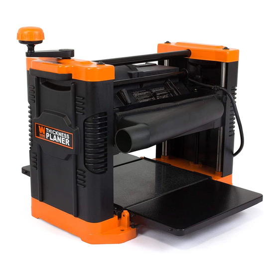
THICKNESS PLANER
IMPORTANT:
NEED HELP? CONTACT US!
Have product questions? Need technical support?
Please feel free to contact us at:
800-232-1195
techsupport@wenproducts.com
WENPRODUCTS.COM
12-1/2 IN.
Model #6550
bit.ly/wenvideo
(M-F 8AM-5PM CST)
Advertisement
Table of Contents

Related Manuals for Wen 6550


Summary of Contents for Wen 6550
- Page 1 IMPORTANT: Your new tool has been engineered and manufactured to WEN’s highest standards for dependability, ease of operation, and operator safety. When properly cared for, this product will supply you years of rugged, trouble-free performance. Pay close attention to the rules for safe operation, warnings, and cautions.
-
Page 2: Table Of Contents
Know Your Planer Assembly and Adjustments Operation Maintenance Troubleshooting Exploded View and Parts List Warranty TECHNICAL DATA Model Number: 6550 Motor: 120V, 60 Hz, 15A, 2.41 HP Cutterhead Speed: 8500 RPM Cuts Per Minute: 17,000 cuts per minute Feed rate: 26 FPM Maximum Depth of Cut: 3/32˝... -
Page 3: General Safety Rules
GENERAL SAFETY RULES Safety is a combination of common sense, staying alert and knowing how your item works. SAVE THESE SAFE- TY INSTRUCTIONS. WARNING: To avoid mistakes and serious injury, do not plug in your tool until the following steps have been read and understood. -
Page 4: Specific Safety Rules For Planer
GENERAL SAFETY RULES 14. NEVER STAND ON A TOOL. Serious injury could result if the tool tips or is accidentally hit. DO NOT store anything above or near the tool. 15. DO NOT OVERREACH. Keep proper footing and balance at all times. Wear oil-resistant rubber-soled foot- wear. -
Page 5: Electrical Information
SPECIFIC RULES FOR THE PLANER 7. Keep hands clear of all moving parts. 8. Do not force cut. Slowing or stalling will overheat motor. Allow automatic feed to function properly. 9. Use quality lumber. Blades last longer and cuts are smoother with good quality wood. 10. -
Page 6: Circuit Breaker
ELECTRICAL INFORMATION WARNING: This tool is for indoor use only. Do not expose to rain or use in damp locations. GUIDELINES FOR USING EXTENSION CORDS Make sure your extension cord is in good condition. When using an extension cord, be sure to use one heavy enough to carry the current your product will draw. -
Page 7: Know Your Planer
KNOW YOUR PLANER Board Return Roller Depth Adjusting Handle Switch Carrying Handle Circuit Breaker Carbon Brushes Extension Table Heavy Duty Granite Table Base ASSEMBLY AND ADJUSTMENTS UNPACKING (Fig. 1) The planer comes assembled as one unit. Additional parts which need to be fastened to planer should be located and accounted for before assembling. - Page 8 ASSEMBLY AND ADJUSTMENTS ATTACHING THE CRANK HANDLE (Fig. 2) It’s time to put this thing together! First, place the washer (Fig. 2 - 3) over the socket head bolt (Fig. 2 - 2) and feed the bolt into the handle (Fig. 2 - 4). Tighten the bolt to secure the handle in posi- tion on top of the planer.
- Page 9 Fig. 9 shows the location of where the holes are located on each side of the planer. Make sure the planer does not rock and that the work table is level. NOTE: We recommend the WEN 6588 Rolling Planer Stand for both stability and easy transportation around the workshop.
-
Page 10: Operation
OPERATION WARNING: Do not connect planer to the power source until all assembly steps have been completed. ON/OFF ON/OFF SWITCH (Fig. 10) Switch The ON/OFF switch is located on the front of the planer motor. To turn the planer ON, move the switch to the up position. To turn the planer Circuit OFF, move the switch to the down position. - Page 11 OPERATION DEPTH OF CUT (Fig. 12) The front of the rollercase features a small 1/16” depth-limit- Handle ing lip in the center of the cutterhead body in order to estab- lish the maximum cutting depth as 1/32” instead of 3/32” for boards wider than 5-3/4”.
- Page 12 OPERATION PREPARE WORK Thickness planers work best when at least one side of the lumber is flat. Use a surface planer or a jointer to create a flat surface. Twisted or severely warped boards can jam the planer and should not be used. Rip lumber in half to reduce magnitude of warp.
- Page 13 OPERATION THE DO’S AND DONT’S OF GRAIN DIRECTION It is important that the cutterhead always cuts in the same direction as the grain. There are six sides to every board: two face grains, two side/edge grains, and two end grains. Never plane with the end grain facing upwards.
-
Page 14: Maintenance
MAINTENANCE CHANGING BLADES (Fig. 13 - 16) FOR VIDEO INSTRUCTIONS VISIT: http://bit.ly/planerblades WARNING: Always turn the planer OFF and disconnect it from the power source before starting any maintenance work. Screws 1. Remove the dust chute by unscrewing the thumb screws that are located in their opposing corners (Fig. - Page 15 MAINTENANCE WARNING: Turn planer off and disconnect from power source before performing any maintenance. BRUSH INSPECTION AND REPLACEMENT (Fig. 17) Brush life depends on the load of the motor. Regularly inspect brushes after 100 hours of use. Brushes are located on either side of the planer motor, on both the front and rear side of the planer.
-
Page 16: Troubleshooting
TROUBLESHOOTING ADJUSTING INFEED/OUTFEED EXTENSION TABLE We recommend setting your infeed and outfeed tables so that the ends of the table extensions are approximately 1 to 2 mm above the top of the granite table. 1. Locate the table elevation adjustment screw and nut on both sides of the planer, next to the hinge (Fig. 18). 2. - Page 17 TROUBLESHOOTING IF THE MATERIAL DOES NOT FEED PROPERLY, CHECK FOR: • dull blades: rotate or replace as necessary (refer to Changing Blades section). • excess clogging in the dust hood (refer to Attach Dust Chute in the Assembly and Adjustments section). •...
-
Page 18: Exploded View And Parts List
EXPLODED VIEW AND PARTS LIST... - Page 19 6550-110 Bolt 6550-132 Support 6550-111 Spacer 6550-133 Retaining Ring 6550-112 Elevating Screw (LH) 6550-134 Bevel Gear 6550-113 Column 6550-135 Elevation Screw Bearing Assembly 6550-114 Screw 6550-136 Right Side Cover 6550-115 Guide 6550-137 Wrench 6550-116 Table 6550-138 Magnet 6550-117 Elevating Screw (RH)
- Page 20 EXPLODED VIEW AND PARTS LIST...
- Page 21 EXPLODED VIEW AND PARTS LIST Item # Stock # Description Item # Stock # Description 6550-201 Dust Exhaust Port 6550-231 Plunger 6550-202 Thumb Screw 6550-232 Spring 6550-203 Set Screw 6550-233 Set Screw 6550-204 Motor Assembly 6550-234 Cutterhead Lock 6550-205 Screw...
-
Page 22: Warranty
LIMITED TWO YEAR WARRANTY WEN Products is committed to building tools that are dependable for years. Our warranties are consistent with this commitment and our dedication to quality. LIMITED WARRANTY OF WEN CONSUMER POWER TOOLS PRODUCTS FOR HOME USE GREAT LAKES TECHNOLOGIES, LLC (“Seller”) warrants to the original purchaser only, that all WEN con- sumer power tools will be free from defects in material or workmanship for a period of two (2) years from date of purchase.
Need help?
Do you have a question about the 6550 and is the answer not in the manual?
Questions and answers