WEN PL1303 - 15-Amp 13-Inch Three-Blade Benchtop Thickness Planer Manual
- Instruction manual (24 pages)
Advertisement
INTRODUCTION
Thanks for purchasing the WEN Benchtop Planer. We know you are excited to put your tool to work, but first, please take a moment to read through the manual. Safe operation of this tool requires that you read and understand this operator's manual and all the labels affixed to the tool. This manual provides information regarding potential safety concerns, as well as helpful assembly and operating instructions for your tool.
 Indicates danger, warning, or caution. The safety symbols and the explanations with them deserve your careful attention and understanding. Always follow the safety precautions to reduce the risk of fire, electric shock or personal injury. However, please note that these instructions and warnings are not substitutes for proper accident prevention measures.
NOTE: The following safety information is not meant to cover all possible conditions and situations that may occur. WEN reserves the right to change this product and specifications at any time without prior notice.
At WEN, we are continuously improving our products. If you find that your tool does not exactly match this manual, please visit wenproducts.com for the most up-to-date manual or contact our customer service at 1-800-232-1195.
Keep this manual available to all users during the entire life of the tool and review it frequently to maximize safety for both yourself and others.
SPECIFICATIONS
| Model Number | PL1303 |
| Motor | 120V, 60 Hz, 15A |
| Cutterhead Speed (No-Load) | 10,000 RPM |
| Number of Blades | 3 Blades |
| Cuts Per Minute | 30,000 |
| Feed Rate | 26 FPM |
| Maximum Depth of Cut | 1/8 Inch (for material < 6 inches wide) |
| 1/16 Inch (for material > 6 inches wide) | |
| Maximum Workpiece Width | 13 Inches |
| Maximum Workpiece Thickness | 6 Inches |
| Dust Chute Adapter Sizes | 2-1/2, 4 Inches |
| Product Dimensions | 24 in. x 28-1/4 in. x 20 in. |
| Product Weight | 63.0 lbs |
GENERAL SAFETY RULES

Read all safety warnings and all instructions. Failure to follow the warnings and instructions may result in electric shock, fire and/or serious injury.
Safety is a combination of common sense, staying alert and knowing how your item works. The term "power tool" in the warnings refers to your mains-operated (corded) power tool or battery-operated (cordless) power tool.
SAVE THESE SAFETY INSTRUCTIONS.
WORK AREA SAFETY
- Keep work area clean and well lit. Cluttered or dark areas invite accidents.
- Do not operate power tools in explosive atmospheres, such as in the presence of flammable liquids, gases or dust. Power tools create sparks which may ignite the dust or fumes.
- Keep children and bystanders away while operating a power tool. Distractions can cause you to lose control.
ELECTRICAL SAFETY
- Power tool plugs must match the outlet. Never modify the plug in any way. Do not use any adapter plugs with earthed (grounded) power tools. Unmodified plugs and matching outlets will reduce risk of electric shock.
- Avoid body contact with earthed or grounded surfaces such as pipes, radiators, ranges and refrigerators. There is an increased risk of electric shock if your body is earthed or grounded.
- Do not expose power tools to rain or wet conditions. Water entering a power tool will increase the risk of electric shock.
- Do not abuse the cord. Never use the cord for carrying, pulling or unplugging the power tool. Keep cord away from heat, oil, sharp edges or moving parts. Damaged or entangled cords increase the risk of electric shock.
- When operating a power tool outdoors, use an extension cord suitable for outdoor use. Use of a cord suitable for outdoor use reduces the risk of electric shock.
- If operating a power tool in a damp location is unavoidable, use a ground fault circuit interrupter (GFCI) protected supply. Use of a GFCI reduces the risk of electric shock.
PERSONAL SAFETY
- Stay alert, watch what you are doing and use common sense when operating a power tool. Do not use a power tool while you are tired or under the influence of drugs, alcohol or medication. A moment of inattention while operating power tools may result in serious personal injury.
- Use personal protective equipment. Always wear eye protection. Protective equipment such as a respiratory mask, non-skid safety shoes and hearing protection used for appropriate conditions will reduce the risk of personal injury.
- Prevent unintentional starting. Ensure the switch is in the off-position before connecting to power source and/or battery pack, picking up or carrying the tool. Carrying power tools with your finger on the switch or energizing power tools that have the switch on invites accidents.
- Remove any adjusting key or wrench before turning the power tool on. A wrench or a key left attached to a rotating part of the power tool may result in personal injury.
- Do not overreach. Keep proper footing and balance at all times. This enables better control of the power tool in unexpected situations.
- Dress properly. Do not wear loose clothing or jewelry. Keep your hair and clothing away from moving parts. Loose clothes, jewelry or long hair can be caught in moving parts.
- If devices are provided for the connection of dust extraction and collection facilities, ensure these are connected and properly used. Use of dust collection can reduce dust-related hazards.
POWER TOOL USE AND CARE
- Do not force the power tool. Use the correct power tool for your application. The correct power tool will do the job better and safer at the rate for which it was designed.
- Do not use the power tool if the switch does not turn it on and off. Any power tool that cannot be controlled with the switch is dangerous and must be repaired.
- Disconnect the plug from the power source and/or the battery pack from the power tool before making any adjustments, changing accessories, or storing power tools. Such preventive safety measures reduce the risk of starting the power tool accidentally.
- Store idle power tools out of the reach of children and do not allow persons unfamiliar with the power tool or these instructions to operate the power tool. Power tools are dangerous in the hands of untrained users.
- Maintain power tools. Check for misalignment or binding of moving parts, breakage of parts and any other condition that may affect the power tool's operation. If damaged, have the power tool repaired before use. Many accidents are caused by poorly maintained power tools.
- Keep cutting tools sharp and clean. Properly maintained cutting tools with sharp cutting edges are less likely to bind and are easier to control.
- Use the power tool, accessories and tool bits, etc. in accordance with these instructions, taking into account the working conditions and the work to be performed. Use of the power tool for operations different from those intended could result in a hazardous situation.
- Use clamps to secure your workpiece to a stable surface. Holding a workpiece by hand or using your body to support it may lead to loss of control.
- KEEP GUARDS IN PLACE and in working order.
SERVICE
- Have your power tool serviced by a qualified repair person using only identical replacement parts. This will ensure that the safety of the power tool is maintained.
CALIFORNIA PROPOSITION 65 WARNING
Some dust created by power sanding, sawing, grinding, drilling, and other construction activities may contain chemicals, including lead, known to the State of California to cause cancer, birth defects, or other reproductive harm. Wash hands after handling. Some examples of these chemicals are:
- Lead from lead-based paints.
- Crystalline silica from bricks, cement, and other masonry products.
- Arsenic and chromium from chemically treated lumber.
Your risk from these exposures varies depending on how often you do this type of work. To reduce your exposure to these chemicals, work in a well-ventilated area with approved safety equipment such as dust masks specially designed to filter out microscopic particles.
PLANER SAFETY WARNINGS
Do not let comfort or familiarity with the product replace strict adherence to product safety rules. Failure to follow the safety instructions may result in serious personal injury.
PLANER SAFETY
- Whenever adjusting or replacing any parts on planer, turn switch OFF and remove plug from power source.
- Make sure all guards are properly attached and securely fastened.
- Make sure all moving parts are free from interference.
- Always wear eye protection or face shield.
- Make sure blades are properly aligned and properly attached to cutterhead.
- Do not plug in planer unless the switch is in the off position. After turning the switch on, allow the planer to come to full speed before operating.
- Keep hands clear of all moving parts.
- Do not force cut. Slowing or stalling will overheat motor. Allow automatic feed to function properly.
- Use quality lumber. Blades last longer and cuts are smoother with good quality wood.
- Do not plane material shorter than 15", narrower than 3/4", wider than 13", or thinner than 1/2".
- Never make a cut deeper than 1/8".
- For workpieces longer than 24", use material support stands.
- Always feed from infeed side to outfeed side, and do not attempt to reverse direction of workpiece being planed while it is being fed through the planer.
- Take precautions against kickback. Do not permit anyone to stand or cross in line of cutterhead's rotation. Kickback or thrown debris will travel in this direction.
- Turn switch off and disconnect power whenever planer is not in use.
- Replace cutting inserts if damaged. Rotate or replace cutting inserts if dull.
- Keep planer maintained. Follow maintenance instructions.
- Don't plane against the grain of the wood. (Refer to Operation Section)
These safety instructions can't possibly warn of every scenario that may arise with this tool, always make sure to stay alert and use common sense during operation.
ELECTRICAL INFORMATION
GROUNDING INSTRUCTIONS
In the event of a malfunction or breakdown, grounding provides the path of least resistance for an electric current and reduces the risk of electric shock. This tool is equipped with an electric cord that has an equipment grounding conductor and a grounding plug. The plug MUST be plugged into a matching outlet that is properly installed and grounded in accordance with ALL local codes and ordinances.
- Do not modify the plug provided. If it will not fit the outlet, have the proper outlet installed by a licensed electrician.
- Improper connection of the equipment grounding conductor can result in electric shock. The conductor with the green insulation (with or without yellow stripes) is the equipment grounding conductor. If repair or replacement of the electric cord or plug is necessary, DO NOT connect the equipment grounding conductor to a live terminal.
- Check with a licensed electrician or service personnel if you do not completely understand the grounding instructions or whether the tool is properly grounded.
- Use only three-wire extension cords that have three-pronged plugs and outlets that accept the tool's plug. Repair or replace a damaged or worn cord immediately.
![]()


In all cases, make certain the outlet in question is properly grounded. If you are not sure, have a licensed electrician check the outlet.
GUIDELINES AND RECOMMENDATIONS FOR EXTENSION CORDS
When using an extension cord, be sure to use one heavy enough to carry the current your product will draw. An undersized cord will cause a drop in line voltage resulting in loss of power and overheating. The table below shows the correct size to be used according to cord length and ampere rating. When in doubt, use a heavier cord. The smaller the gauge number, the heavier the cord.
| AMPERAGE | REQUIRED GAUGE FOR EXTENSION CORDS | |||
| 25 ft. | 50 ft. | 100 ft. | 150 ft. | |
| 15A | 14 gauge | 12 gauge | Not Recommended | Not Recommended |
- Examine extension cord before use. Make sure your extension cord is properly wired and in good condition. Always replace a damaged extension cord or have it repaired by a qualified person before using it.
- Do not abuse extension cord. Do not pull on cord to disconnect from receptacle; always disconnect by pulling on plug. Disconnect the extension cord from the receptacle before disconnecting the product from the extension cord. Protect your extension cords from sharp objects, excessive heat and damp/wet areas.
- Use a separate electrical circuit for your tool. This circuit must not be less than a 12-gauge wire and should be protected with a 15A time-delayed fuse. Before connecting the motor to the power line, make sure the switch is in the OFF position and the electric current is rated the same as the current stamped on the motor nameplate. Running at a lower voltage will damage the motor.
UNPACKING & PACKING LIST
UNPACKING
With the help of a friend or trustworthy foe, such as one of your in-laws, carefully remove the planer from the packaging and place it on a sturdy, flat surface. Make sure to take out all contents and accessories. Do not discard the packaging until everything is removed. Check the packing list below to make sure you have all of the parts and accessories. If any part is missing or broken, please contact customer service at 1-800-232-1195 (M-F 8-5 CST), or email techsupport@wenproducts.com.
PACKING LIST

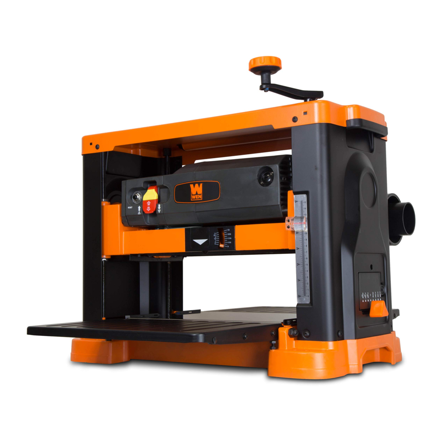
KNOW YOUR PLANER
TOOL PURPOSE
Resurface boards, flatten workpieces, and much more with your WEN Thickness Planer. Refer to the diagram below to become familiarized with the parts and controls of your thickness planer.
PLANER

ASSEMBLY & ADJUSTMENTS
ATTACHING THE DEPTH ADJUSTMENT HANDLE
- Secure the depth adjustment handle (Fig. 2 - 1) to the top of the planer using the included socket head cap screw (Fig. 2 - 2).

- Flip the depth adjustment handle over so the socket head cap screw is covered.

NOTE: Each full rotation of the depth-adjustment handle adjusts the planer's height by 1/16". For example, 1/4 of a rotation is 1/64", 1/2 of a rotation is 1/32", and 1 full rotation is 1/16".
PREPARING THE TABLES
- Lower the infeed and outfeed tables (Fig. 3 - 1). Wipe off any protective coating with a shop towel.

- Remove the foam blocks placed between the table and the rollercase. Peel back the protective film from the table.
- Apply a light coat of good-quality paste wax to the infeed and outfeed tables, as well as the main table. Follow the manufacturer's directions. This will protect the tables and help workpieces move through the planer smoothly.

ADJUSTING THE INFEED/OUTFEED EXTENSION TABLES
The infeed and outfeed table levels have been set from the factory, and should require no adjustment. However, if you find that they are out of adjustment from shipping, follow the directions to adjust them.
ATTACHING THE DUST CHUTE
- Make sure the hex wrench and star wrench are mounted on the dust chute. They can be stored here for easy access.
- Remove the knobs from the top of the rollercase (Fig. 4 - 1).

- Set the dust chute (Fig. 4 - 2) on the rollercase as shown in Fig. 4. Secure it using the knobs removed in step 2.
- Connect a dust collection system or shop vacuum to the dust chute. The dust chute can be connected to a 2-1/2" or 4" hose. You may need to use a hose clamp (not included). Be sure to turn the dust collection system or shop vacuum on before operating the planer.

NOTE: If you do not plan on using a dust collection system of any kind, you may open up the bottom of the dust chute to allow wood chips and shavings to fly out the back of your planer. This will, however, make a mess in your shop. Alternatively, you may leave the chute closed and regularly clean the wood shavings and dust out of the planer and chute during operation. Any damage or other problem caused by a failure to keep the planer clean (by not using dust collection, removing wood chips, etc.) is not covered under the warranty. Keep your planer clean.
MOUNTING THE PLANER TO A WORK SURFACE
The planer should always be mounted to a stable, level bench or table in a well-lit area. Make sure there is plenty of room for maneuvering the workpiece through the entire cut. Neither the operator nor bystanders should stand in line with the workpiece while the tool is operating.
- Mount the planer to a workbench or tool stand using four bolts, four flat washers, and four hex nuts (not included) through the mounting holes on the base (Fig. 5). There are eight mounting holes – one set of two holes at each corner.


NOTE: We recommend the WEN 6588T or MSA658 Planer Stand for both stability and easy transportation around the workshop.
OPERATION
Do not connect planer to the power source Fig. 6 until all assembly steps have been completed.
ON/OFF SWITCH
The ON / OFF switch (Fig. 6 - 1) is located on the front of the planer motor. To turn the planer ON, make sure the safety key is inserted, and flip the switch to the up position. To turn the planer OFF, flip the switch to the down position.

SWITCH LOCKOUT
Remove the yellow safety key (Fig. 6 - 2) to engage child-safety lock and prevent unwanted start-ups. To lock the switch, flip the switch to the OFF position and disconnect the planer from its power source. Pull the safety key out (Fig. 6 - 2). The machine cannot be turned ON with the key removed. To turn the machine back ON, slide the key into the slot on the switch until it snaps into place, then flip the switch up.
NOTE: The key can be removed from the switch while in the ON position. This allows for the machine to be turned OFF, but prevents it from being turned back ON while the key is removed.
CIRCUIT BREAKER
This planer is equipped with a circuit breaker to protect the motor (Fig. 6 - 3). The breaker will automatically shut the planer off when excessive current is drawn. If the breaker is tripped, turn the planer off, wait a moment to allow the breaker to cool down, and reset the circuit by pressing the button. If the button pops back out, wait a few more minutes to allow it to cool down more. Reduce the depth of cut, reset the breaker, and try again.
Be sure to turn the planer off prior to resetting the circuit breaker to avoid unintentional start-up of the planer.
AVOID DAMAGE TO BLADES
Thickness planers are a precision woodworking machine and should be used on quality lumber only. Do not plane dirty boards; dirt and small stones are abrasive and will wear out the cutting inserts.
REMOVE NAILS AND STAPLES. Use planer to cut wood only. Avoid knots. Heavily cross-grained wood makes knots hard. Knots can come loose and jam blade.
Any article that encounters planer blades may be forcibly ejected from the planer, creating a risk of injury. Make sure the wood is free from foreign materials before attempting to plane.
HEIGHT OF CUT
Rotate the depth adjustment handle (Fig. 7 - 1) to adjust the height of the rollercase, relative to the base. The depth scale (Fig. 7 - 2) shows the height of the cutterhead above the main table.

The quality of the finished surface depends on the operator's experience and judgment about the depth of cut. Each full rotation of the depth-adjustment handle adjusts the planer's height by 1/16". For example, 1/4 of a rotation is 1/64", 1/2 of a rotation is 1/32", and 1 full rotation is 1/16".
NOTE: When adjusting the height of the rollercase, ensure the depth stop preset (Fig. 8 - 1) is in the lowest (thinnest) position. Failure to do so may result in damage to the depth stop preset or the rollercase.

A spring-loaded depth-of-cut gauge (Fig. 7 - 3) is attached to the front of the rollercase. The pointer on the depthof-cut gauge accurately displays the depth of cut per pass when the workpiece is positioned below the gauge.
Never plane against the grain direction of the wood. Do not plane end grain, as the wood could splinter or possibly explode.
Do not plane any board shorter than 14-1/2"; the force of the cut could split the board and cause kickback.
DEPTH OF CUT
- The depth of cut depends on the width, species, hardness, moisture content, grain direction, and grain structure of the wood.
- The maximum depth of cut is 1/8" for workpieces less than 6" wide, and 1/16" for workpieces wider than 6". The wider the workpiece, the shallower the depth of cut should be. The harder the species of wood, the shallower the depth of cut should be.
- The smaller the depth of cut, the better the finished surface. It is better to take multiple shallow passes on a work-piece, rather than one deep pass; this is better for the motor and cutting inserts, and will prolong their lives.
- If boards are cupped or bowed, use a jointer to flatten them out, or take multiple shallow passes until the work has one flat side. Once a level surface has been created, flip the workpiece and create parallel sides. It is easiest to do this if you can rip-cut the boards into multiple pieces beforehand.
- As a rule of thumb, it is best to alternate sides of the board being planed until the desired thickness is reached. This will result in the board having a more-uniform moisture content, since half of the total depth of cut has been taken from each side. Any additional drying should not cause warping or cupping.
- Scrap wood is your best friend. Make a cut on a test piece to verify the finish produced, as well as the accuracy of the depth of cut and the thickness of the finished product.
DEPTH STOP
The depth stop preset (Fig. 8 - 1) is a simple way to set the desired thickness of a workpiece. Move the knob to the desired finished thickness. For example, if you want a workpiece 1-1/4" thick, move the knob to the 1-1/4" setting. The finished workpiece will be 1-1/4" thick. This feature is best used when planing multiple workpieces, in order to ensure that all workpieces have a uniform thickness.
NOTE: when adjusting the height of the rollercase, ensure the depth stop preset is in the lowest (thinnest) position. Failure to do so may result in damage to the depth stop preset or the rollercase.
PREPARING WORK
Thickness planers work best when at least one side of the lumber is flat. Use a surface planer or a jointer to create a flat surface. Twisted or severely warped boards can jam the planer and should not be used. Rip lumber in half to reduce the magnitude of warpage.
Work should be fed into the planer in the same direction as the grain of the wood. Sometimes the grain will change direction in the middle of the board. In such cases, if possible, cut the board in the middle before planing, so that the grain direction is correct. Always plane with the grain.
Never plane against the grain direction of the wood. Do not plane end grain, as the wood could splinter or possibly explode.
Do not plane any board shorter than 14-1/2"; the force of the cut could split the board and cause kickback.
CHECK FOR WORN BLADES
The blades' condition will affect cutting precision. Observe the quality of the cut that the planer produces to check the condition of the blades. Dull blades will tear wood fibers and produce fuzzy surfaces. Raised grain will occur when dull blades pound on wood that has varying density. Raised edges will also be produced where the blades have been nicked. The blades on this planer are adjustable. Keeping a spare set of blades on hand is recommended. Replacement blades can be ordered from wenproducts.com (model numbers BP133K and BP133M).
AVOIDING SNIPE
Thickness planers tend to leave a small bit of snipe at the end of the planed boards, particularly for longer workpieces. Snipe is a small dip that is caused by the board's own weight pulling one end downwards as the board enters or exits the planer, thus pushing the other end into the cutterhead and creating an uneven finish. Snipe will occur when boards are not supported properly, or when only one feed roller is in contact with the work at beginning or end of cut.
The best way to avoid snipe is to cut your workpiece long enough that you can saw off the snipe after the board has been planed. Leave 1" to 2" on both ends so it can be removed later. Other, less efficient methods include gently pushing the board up while feeding the work until the outfeed roller starts advancing it. Then, move to the rear and receive the planed board by gently pushing it up when the infeed roller loses contact with it. The third option is to have another dummy board flush against the beginning and end of the workpiece. That way, this piece of scrap wood will be the recipient of all of the snipe. Snipe is more apparent when deeper cuts are taken. Lower depths help prevent snipe.
It is also recommended to have the infeed and outfeed extension tables slightly inclined upwards to form a V shape, with the difference between the outermost edges of the extension tables and the center of the main table being about 1 mm.
THE DO'S AND DONT'S OF GRAIN DIRECTION

Always plane with the grain of the wood (in the same direction as the grain). There are six sides to every board: two face grains, two side/edge grains, and two end grains. Never plane with the end grain facing upwards. Only plane side and face grains. Otherwise, the board could splinter and explode inside the planer, which could cause serious injury and damage. When planing the face and side/edge grain, always plane in the direction of the grain. Do not plane perpendicular to the grain, otherwise the board could splinter and explode.
Never plane against grain direction of the wood. Do not plane end grain, as the wood could splinter or possibly explode.
FEEDING WORK
The planer is supplied with blades mounted in the cutterhead, and the infeed and outfeed rollers pre-adjusted to the correct heights. The feed rate (the rate at which the workpiece travels through the planer) is automatic, but will vary slightly depending on the depth of cut and type of wood. To feed the workpiece:
- Align the work perpendicular to the rollercase so that the work feeds through the planer straight, making surethat the board is traveling in the same direction as the grain and that you are only planing either side or face grain. Boards longer than 24" should have additional support from free-standing material stands. Position the workpiece with the face to be planed on top.
- Raise / lower rollercase to produce the depth of cut desired.
- Stand on the side of the planer. Do not stand directly in front or behind the planer.
- Turn the planer ON and direct the board into the planer. Gently slide workpieces into the infeed side of the planer until the infeed roller advances the workpiece. Let go of the workpiece and allow the automatic feed to advance the board through the planer.
- Do not push or pull on workpiece. Catch the planed lumber by grasping it in same manner as it was fed as it comes out the back side. Make sure not to stand directly behind the planer while catching fed lumber. Do not grasp any portion of board which has not gone past the outfeed roller
![]()
To avoid risk of injury due to kickback, do not stand directly in line with the front or rear of planer. - Repeat as needed. Keep in mind that multiple shallow cuts result in smoother surfaces than a single deeper cut.
NOTE: Assistant must follow same precautions as operator.
MAINTENANCE
REPLACING BLADES
Always turn the planer OFF and disconnect it from the power source before starting any maintenance work.
Blades should always be reversed or replaced as a matched set (at the same time).
NEVER grasp the cutterhead with unprotected hands. This will result in serious injury.
- Get the magnetic blade tool.
- Adjust the rollercase to a height of about 2-1/4" (refer to the depth scale, Fig. 7 - 2). Remove the dust chute.
- Insert the included hex wrench into the hole above the depth stop label (Fig. 10; adjust the height of the rollercase if necessary). Use the hex wrench to turn the cutterhead, so the blades are easily accessible. The cutterhead lock will automatically engage when the cutterhead is in the right position.

- Use the star wrench to loosen the 7 mounting bolts about 4 - 5 turns (Fig. 11). Do not remove the bolts from the gib.
- With the hook-and-loop side of the magnetic blade tool facing down, slide the magnetic strip between the blade and the gib. Make sure the tool is centered on the blade.

![]()
Blade edges are extremely sharp. Keep fingers away from the blades at all times. - The blade is located in position by two pins. Gently lift the old blade off the cutterhead and slide it out from under the gib. Do not make contact with the blade with your bare fingers (Fig. 12).

- Clean off any dust or debris from blade, as well as the cutterhead.
![warning]() NOTE: Proper cleaning of the blades and cutterhead is crucial to achieving a good-quality cut. Dirt or dust trapped between the blade and cutterhead may cause the blade to be improperly mounted, and create noticeable marks on the workpiece.
NOTE: Proper cleaning of the blades and cutterhead is crucial to achieving a good-quality cut. Dirt or dust trapped between the blade and cutterhead may cause the blade to be improperly mounted, and create noticeable marks on the workpiece.


- Reverse or replace blade. Place it on the center of the magnetic blade tool, and carefully position the blade on the two pins on the cutterhead. Then remove the blade tool.
- Using the star wrench, tighten the 7 bolts loosened in step 4. This will clamp the gib snugly against the blades.
- Repeat the steps above to change the second and third blades. (In order to access the other blades, you will need to press down on the cutterhead lock with one hand, while turning the hex wrench with the other.)
- Replace the dust chute. Remove the hex wrench from the cutterhead.
The magnetic blade tool can be stored on underside of the outfeed extension table, using the hook-and-loop strip.
ADJUSTING THE INFEED/OUTFEED EXTENSION TABLES
For best results and to minimize snipe, we recommend setting the infeed and outfeed tables so that the end of each extension table is about 1mm above the top of the main table.
- Locate the table elevation adjustment screw and nut on each side of the table, next to the hinge. Raise the table to expose the screw and nut.
- Using a wrench and screwdriver, loosen the screw while holding the nut steady. Keep track of the number of turns applied to each screw. Make sure that the screws on the left and right sides of the table are turned the same number of times.
- When both screws are adjusted to the height you want the table to be, tighten down the nut against the base ofthe planer while holding the screw head steady. Repeat for the other screw.
- Test the table height. If adjustments need to be made, repeat steps 2 to 3 as needed, ensuring that both screwshave been turned the same number of times.
- Repeat steps 1 – 4 for the other table until you are satisfied with the height.
- Test the adjustments on a scrap piece of wood, making further adjustments as necessary until you are satisfied.
CARBON BRUSH INSPECTION & REPLACEMENT
Brush life depends on the load of the motor. Regularly inspect brushes after 100 hours of use. Brushes are located on either side of the planer motor, on both the front and rear side of the planer. Loosen brush cap (Fig. 12 - 1) and carefully remove brush from motor. Replace brushes if the spring is damaged. Replace brushes if the carbon is worn down to 3/16" long or shorter. Tighten brush caps after replacement. Both brushes should be replaced simultaneously. Replacement brushes can be purchased from wenproducts.com (part no. PL1326-189).
LUBRICATION

The motor and cutterhead bearings are sealed and need no lubrication. Keep the elevation leadscrew chain (located under the bottom of the planer) lubricated with a dry chain lubricant. Do not over-lubricate.
CLEANING THE PLANER
Keep planer clean of any wood chips, dust, dirt or debris. We strongly recommend always using a dust collection system. Make sure to clean out the planer after every use.
After 10 hours of operation, the drive chains and sprockets should have wood chips, dust and old grease removed. While wearing ANSI-Z87.1-approved safety glasses, use a couple puffs of compressed air (do not exceed 50 PSI) to blow dust and chips out of the gearbox and drive chains.
Use common automotive bearing grease to lubricate all drive chains and sprockets. Spray the gearbox with a light coat of dry lubricant. Clean the table and infeed / outfeed rollers using a soft, damp cloth. Do not use any waxes, oils or solvents on the table.
NOTE: The buildup of dust, wood shavings, and other debris can significantly shorten the planer's useful life. Keep your planer clean! Failure to do so will void the warranty.
TROUBLESHOOTING GUIDE
Stop using the tool immediately if any of the following problems occur. Repairs and replacements should only be performed by an authorized technician. For any questions, please contact our customer service at 1-(800) 232-1195, M-F 8-5 CST or email us at techsupport@wenproducts.com.
| PROBLEM | CAUSE | SOLUTION |
| Machine does not start. | Machine is not plugged in. | Plug machine in. |
| Wrong extension cord size used. | Use properly-sized extension cord. | |
| Power outlet does not have power. | Check power outlet for power. Check breaker for associated circuit. Contact a professional electrician if necessary. | |
| Safety key not installed. | Install safety key. | |
| Breaker tripped. | Reset breaker. | |
| Worn carbon brushes. | Replace carbon brushes. | |
| Material does not feed properly. | Dull cutting inserts. | Check cutting inserts. Rotate or replace as necessary. |
| Excessive material has built up in the dust chute. | Clean out the dust chute. Always use a dust collection system. | |
| Broken gearbox or drive chain. | Contact customer service at 1-800232-1195 for assistance. | |
| Circuit breaker keeps tripping. | Wrong extension cord size used. | Use properly-sized extension cord. |
| Dull cutting inserts. | Check cutting inserts. Rotate or replace as necessary. | |
| Excessive depth of cut. | Reduce depth of cut. | |
| Internal motor problem. | Contact customer service at 1-800232-1195 for assistance. | |
| Drive rollers do not work, or excessively loud grinding noise. | Broken gearbox, drive chain, or sprocket. | Contact customer service at 1-800232-1195 for assistance. |
| Marks on the workpiece. | Dull cutting inserts. | Check cutting inserts. Rotate or replace as necessary. |
| Excessive depth of cut. | Reduce depth of cut. | |
| Workpiece being fed against grain. | Reverse workpiece. | |
| Table or feed rollers are dirty. | Clean table and/or feed rollers. | |
| Dust or debris between cutting inserts and cutterhead. | Clean cutting inserts and cutterhead. | |
| Snipe. | Dull cutting inserts. | Check cutting inserts. Rotate or replace as necessary. |
| Improper support being used. | Support workpiece properly (especially long workpieces). | |
| Infeed or outfeed table improperly adjusted. | Adjust infeed and outfeed tables. | |
| Table or feed rollers are dirty. | Clean table and/or feed rollers. |
To purchase accessories for your tool, visit WENPRODUCTS.COM
Multi-Purpose Planer Stand (Model 6588T)
Multi-Purpose Rolling Planer and Miter Saw Stand (Model MSA658)
Replacement Blades, 3-pack, SK5 Steel (Model BP133K)
Replacement Blades, 3-pack, M2 Steel (Model BP133M)
Have product questions? Need technical support? Please feel free to contact us:
1-800-232-1195 (M-F 8AM-5PM CST)
TECHSUPPORT@WENPRODUCTS.COM
For replacement parts visit WENPRODUCTS.COM

Documents / Resources
References
![wenproducts.com]() WEN - Shop Generators, Woodworking Tools, and Power Tools — WEN Products
WEN - Shop Generators, Woodworking Tools, and Power Tools — WEN Products![wenproducts.com]() WEN - Shop Generators, Woodworking Tools, and Power Tools — WEN Products
WEN - Shop Generators, Woodworking Tools, and Power Tools — WEN Products
Download manual
Here you can download full pdf version of manual, it may contain additional safety instructions, warranty information, FCC rules, etc.
Download WEN PL1303 - 15-Amp 13-Inch Three-Blade Benchtop Thickness Planer Manual
Advertisement


Need help?
Do you have a question about the PL1303 and is the answer not in the manual?
Questions and answers