Table of Contents
Advertisement
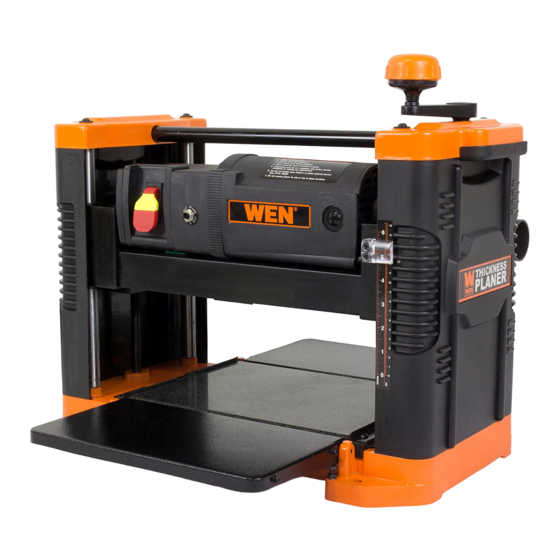
12.5-INCH
THICKNESS PLANER
Instruction Manual
NEED HELP? CONTACT US!
Have product questions? Need technical support? Please feel free to contact us:
1-800-232-1195 (M-F 8AM-5PM CST)
TECHSUPPORT@WENPRODUCTS.COM
IMPORTANT: Your new tool has been engineered and manufactured to WEN's highest standards for dependability,
ease of operation, and operator safety. When properly cared for, this product will supply you years of rugged,
trouble-free performance. Pay close attention to the rules for safe operation, warnings, and cautions. If you use
your tool properly and for its intended purpose, you will enjoy years of safe, reliable service.
WENPRODUCTS.COM
For replacement parts and the most up-to-date instruction manuals, visit
Advertisement
Table of Contents

Related Manuals for Wen 6550


Summary of Contents for Wen 6550
- Page 1 1-800-232-1195 (M-F 8AM-5PM CST) TECHSUPPORT@WENPRODUCTS.COM IMPORTANT: Your new tool has been engineered and manufactured to WEN’s highest standards for dependability, ease of operation, and operator safety. When properly cared for, this product will supply you years of rugged, trouble-free performance. Pay close attention to the rules for safe operation, warnings, and cautions. If you use your tool properly and for its intended purpose, you will enjoy years of safe, reliable service.
-
Page 2: Table Of Contents
Troubleshooting Guide ................... 17 Exploded View & Parts List ................18 Warranty Statement ..................22 WENPRODUCTS.COM To purchase accessories for your tool, visit Multi-Purpose Planer Stand (Model No. 6588T) Planer Miter Saw Stand (Model No. MSA658) Replacement Thickness Planer Blades (Model No. 6550-242) -
Page 3: Welcome
INTRODUCTION Thanks for purchasing the WEN Thickness Planer. We know you are excited to put your tool to work, but first, please take a moment to read through the manual. Safe operation of this tool requires that you read and understand this operator’s manual and all the labels affixed to the tool. -
Page 4: Safety
GENERAL SAFETY RULES WARNING! Read all safety warnings and all instructions. Failure to follow the warnings and instructions may result in electric shock, fire and/or serious injury. Safety is a combination of common sense, staying alert and knowing how your item works. The term “power tool” in the warnings refers to your mains-operated (corded) power tool or battery-operated (cordless) power tool. - Page 5 GENERAL SAFETY RULES WARNING! Read all safety warnings and all instructions. Failure to follow the warnings and instructions may result in electric shock, fire and/or serious injury. Safety is a combination of common sense, staying alert and knowing how your item works. The term “power tool” in the warnings refers to your mains-operated (corded) power tool or battery-operated (cordless) power tool.
-
Page 6: Planer Safety Warnings
PLANER SAFETY WARNINGS WARNING! Do not let comfort or familiarity with the product replace strict adherence to product safety rules. Failure to follow the safety instructions may result in serious personal injury. PLANER SAFETY 10. Do not plane material shorter than 15”, nar- rower than 3/4”, wider than 12-1/2”... -
Page 7: Electrical Information
ELECTRICAL INFORMATION GROUNDING INSTRUCTIONS In the event of a malfunction or breakdown, grounding provides the path of least resistance for an electric current and reduces the risk of electric shock. This tool is equipped with an electric cord that has an equipment grounding conductor and a grounding plug. -
Page 8: Before Operating
UNPACKING & PACKING LIST UNPACKING With the help of a friend or trustworthy foe, such as one of your in-laws, carefully remove the planer from the packaging and place it on a sturdy, flat surface. Make sure to take out all contents and accessories. Do not discard the packaging until everything is removed. -
Page 9: Know Your Planer
KNOW YOUR PLANER TOOL PURPOSE Resurface boards, flatten workpieces, and much more with your WEN Thickness Planer. Refer to the diagram below to become familiarized with the parts and controls of your thickness planer. Board Return Roller Depth Adjustment Handle... -
Page 10: Assembly & Adjustments
ASSEMBLY & ADJUSTMENTS ATTACHING THE DEPTH ADJUSTMENT HANDLE Fig. 2 1. Secure the depth adjustment handle (Fig. 2 - 1) to the top of the planer using the included socket head bolt (Fig. 2 - 2) and washer (Fig. 2 - 3). 3. -
Page 11: Operation & Maintenance
OPERATION WARNING! Do not connect planer to the power source until all assembly steps have been completed. ON / OFF SWITCH Fig. 6 The ON / OFF switch (Fig. 6 - 1) is located on the front of the planer mo- tor. - Page 12 OPERATION HEIGHT OF CUT Fig. 7 Rotate crank handle (Fig. 7 - 1) to adjust height of cut- terhead. The depth scale (Fig. 7 - 2) shows height of the cutterhead above the main table. The quality of the planed wood depends on the operator’s experience and judgment about the depth of cut.
- Page 13 OPERATION PREPARE WORK Thickness planers work best when at least one side of the lumber is flat. Use a surface planer or a jointer to create a flat surface. Twisted or severely warped boards can jam the planer and should not be used. Rip lumber in half to reduce magnitude of warp.
- Page 14 OPERATION THE DO’S AND DONT’S OF GRAIN DIRECTION Fig. 8 Always plane with the grain of the wood (in the same direction as the grain). There are six sides to every board: two face grains, two side/edge grains, and two end grains. Never plane with the end grain facing upwards.
-
Page 15: Maintenance
MAINTENANCE CHANGING BLADES Fig. 9 WARNING! Always turn the planer OFF and disconnect it from the power source before starting any maintenance work. For video instructions, visit: http://bit.ly/planerblades Blades should always be reversed or replaced as a matched set (at the same time). - Page 16 MAINTENANCE WARNING! Turn planer off and disconnect from power source before performing any maintenance. BRUSH INSPECTION AND REPLACEMENT Fig. 13 Brush life depends on the load of the motor. Regularly inspect brushes after 100 hours of use. Brushes are located on either side of the planer motor, on both the front and rear side of the planer.
-
Page 17: Troubleshooting Guide
TROUBLESHOOTING GUIDE ADJUSTING INFEED / OUTFEED EXTENSION TABLE We recommend setting your infeed and outfeed tables so that the ends of the table extensions are approximately 1mm above the top of the granite table. 1. Locate the table elevation adjustment screw and nut on both sides of the planer, next to the hinge (Fig. 14). 2. -
Page 18: Exploded View & Parts List
EXPLODED VIEW & PARTS LIST... - Page 19 EXPLODED VIEW & PARTS LIST Part No. Description Qty. Part No. Description Qty. 6550-101 Screw 6550-120 Base 6550-101A Flat Washer, 6mm 6550-121 Plate 6550-102 Left Cap 6550-122 Set Screw 6550-103 Cotter Pin 6550-123 6550-104 Roller 6550-124 Adjustment Screw 6550-105 Handle Assembly...
- Page 20 EXPLODED VIEW & PARTS LIST...
- Page 21 EXPLODED VIEW & PARTS LIST Part No. Description Qty. Part No. Description Qty. 6550-201 Dust Exhaust Port 6550-232 Spring 6550-202 Thumb Screw 6550-233 Set Screw 6550-203 Set Screw 6550-234 Cutterhead Lock 6550-204B Motor Assembly 6550-235 Spacer 6550-205 Screw 6550-236 Screw...
-
Page 22: Warranty Statement
WARRANTY STATEMENT WEN Products is committed to building tools that are dependable for years. Our warranties are consistent with this commitment and our dedication to quality. LIMITED WARRANTY OF WEN PRODUCTS FOR HOME USE GREAT LAKES TECHNOLOGIES, LLC (“Seller”) warrants to the original purchaser only, that all WEN consumer power tools will be free from defects in material or workmanship during personal use for a period of two (2) years used for professional or commercial use. - Page 23 NOTES...
- Page 24 THANKS FOR REMEMBERING V. 2020.02.10...
Need help?
Do you have a question about the 6550 and is the answer not in the manual?
Questions and answers