
Related Manuals for Raymarine CP200


Summary of Contents for Raymarine CP200
-
Page 1: Installation Instructions
CP100 / CP200 Installation instructions Date: 07-2014 Document number: 87216-1-EN © 2014 Raymarine UK Limited... - Page 2 Trademark and patents notice Raymarine, Tacktick, Clear Pulse, Truzoom, HSB, SeaTalk, SeaTalk , SeaTalk , Micronet, Raytech, Gear Up, Marine Shield, Seahawk, Autohelm, Automagic, and Visionality are registered or claimed trademarks of Raymarine Belgium. FLIR, DownVision, SideVision, Dragonfly, Instalert, Infrared Everywhere, and The World’s Sixth Sense are registered or claimed trademarks of FLIR Systems, Inc.
-
Page 3: Chapter 1: Important Information
Raymarine approved installer. A certified installation product also features an isolated power qualifies for enhanced product warranty benefits. supply. Contact your Raymarine dealer for further details, and refer to the separate warranty document packed with your product. Warning: High voltage This product contains high voltage. -
Page 4: Water Ingress
If a ferrite has to be removed for any purpose (e.g. installation or maintenance), it must be Raymarine does not warrant that this product is replaced in the original position before the product error-free or that it is compatible with products is used. -
Page 5: Chapter 2: Document And Product Information
Chapter 2: Document and product information Chapter contents • 2.1 Document information • 2.2 Parts supplied • 2.3 Product overview • 2.4 CHIRP Sonar overview • 2.5 CHIRP DownVision overview • 2.6 CHIRP SideVision™ overview • 2.7 Interpreting SideVision™ images •... -
Page 6: Document Information
Description Part number module and SideVision CP100 / CP200 Installation instructions 87216 / transom Installation of a CP100 or CP200 unit and 88030 transducer. connection to a wider system of marine electronics. 87193 CP100 / CP200 Mounting template Mounting diagram for surface mounting a CP100 or CP200 unit. -
Page 7: Parts Supplied
2.2 Parts supplied Description Part number a Series, c Series, e Series Installation and 81337 Parts supplied — CP100 / CP200 operation instructions Details the operation of the fishfinder application (including DownVision and SideVision operation) for a Series, c Series, e Series multifunction displays. -
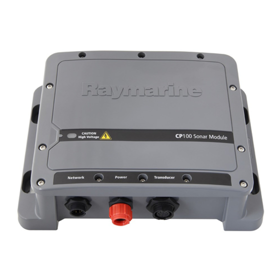
Page 8: Product Overview
• Waterproof to IPX 6 and IPX 7. • Robust and waterproof high-speed network connection. CP200 product overview The CP200 is a CHIRP sonar module with SideVision capabilities. In conjunction with a compatible multifunction display, the CP200 provides a detailed view of the water’s bottom structure on... -
Page 9: Chirp Sonar Overview
2.4 CHIRP Sonar overview 2.5 CHIRP DownVision overview CHIRP sonar produces a conical shaped beam, the DownVision produces a wide–angle side-to-side coverage of the conical beam is the water column beam and a thin fore-to-aft beam. The coverage of directly beneath the vessel the DownVision beam is a water column directly beneath and to the sides of the vessel. - Page 10 The narrow angle the beams make with the bottom at longer ranges can reveal the shadows of structures that protrude from the bottom. CHIRP SideVision™ screen example CP100 / CP200...
- Page 11 2.7 Interpreting SideVision™ images The following illustration shows how SideVision™ images on your multifunction display are related to the water column and sea floor to the sides of your vessel. Interpreting SideVision images Ve s s e l S TARBOARD direction dire ction Distance...
- Page 12 1. A DownVision™ sounder: either an internal sounder in a DownVision™ variant multifunction display, or an external DownVision™ sonar module (such as a CP100). 2. An external SideVision™ sonar module (such as a CP200). CP100 / CP200...
-
Page 13: Chapter 3: Planning The Installation
Chapter 3: Planning the installation Chapter contents • 3.1 Installation checklist • 3.2 Required additional components • 3.3 Compatible multifunction displays • 3.4 Software updates • 3.5 Compatible transducers • 3.6 Tools required • 3.7 Typical systems • 3.8 Warnings and cautions •... -
Page 14: Installation Checklist
Obtain all required equipment and tools. mount. Refer to 3.5 Compatible transducers for a list of compatible products. Site all equipment. • Compatible Raymarine multifunction display. Route all cables. Refer to 3.3 Compatible multifunction displays for Drill cable and mounting holes. -
Page 15: Compatible Multifunction Displays
This product is compatible with the following The software running on the product can be updated. LightHouse powered Raymarine multifunction • Raymarine periodically releases software updates displays. to improve product performance and add new • a Series, c Series, e Series. -
Page 16: Compatible Transducers
Bronze Down- hull Vision Adhesive tape trans- ducer CP200 compatible transducers This product is compatible with the following Note: * The appropriate drill bit size is dependent Raymarine transducers. on the thickness and material of the mounting surface. Part Descrip-... -
Page 17: Typical Systems
Note: The following illustrations show the various products that can be connected in a typical system. • Systems that include a CP200 sonar module can use a SideVision transducer in place of the illustrated DownVision transducer. -
Page 18: Warnings And Cautions
In this situation, when choosing the installation location for your product, ensure that the compass is not affected by the product when it is in a powered state. CP100 / CP200... -
Page 19: Product Dimensions
3.10 Product dimensions 72 mm (2.8 in) 205 mm (8.1 in) 225 mm (8.9 in) D12941-1 Planning the installation... -
Page 20: Chapter 4: Cables And Connections
Chapter 4: Cables and connections Chapter contents • 4.1 General cabling guidance • 4.2 Connections overview • 4.3 Power connection • 4.4 Transducer connections • 4.5 Network connection Cables and connections... -
Page 21: General Cabling Guidance
3rd party audio amplifier. of the correct type, supplied by Raymarine. • Always use an RS232/NMEA converter with • Ensure that any non-Raymarine cables are of the optical isolation on the signal lines. correct quality and gauge. For example, longer •... -
Page 22: Connections Overview
2-wire cable from the unit to the vessel's battery or connector fully onto the corresponding connector distribution panel. on the unit. • Raymarine recommends a minimum wire gauge 4. Turn the locking collar clockwise to secure the of 18AWG (0.82 mm ) for any length of cable cable. -
Page 23: Sharing A Breaker
If your vessel does not have a distribution panel accordance with the instructions in this or an RF ground point then your product may be guide. wired directly to the battery with the drain wire also connected to the battery’s negative terminal. CP100 / CP200... -
Page 24: Transducer Connections
Transducer connection — SideVision The CP200 sonar module is designed for use with SideVision transducers. • Refer to CP200 compatible transducers for a list of compatible transducers. • Transducers must be installed in accordance with the instructions provided with the transducer. -
Page 25: Network Connection
Item Description list of suitable transducer extension cables. Sonar module. • Raymarine recommends a maximum of one cable Connector panel for compatible Raymarine extension for any single transducer cable. multifunction display. • For best performance, keep all cable lengths to RayNet cable. - Page 26 Multiple multifunction display configuration A Raymarine network switch can be used to connect the unit to more than 1 multifunction display. Note: Ensure network cables and connections are tight and secure using any cable ties provided with your network hardware.
-
Page 27: Chapter 5: Mounting
Chapter 5: Mounting Chapter contents • 5.1 Mounting Mounting... -
Page 28: Mounting The Unit
Mounting the unit the unit is to be mounted on. Having chosen a suitable location, install the unit as follows: Note: Raymarine recommends mounting the unit vertically. 1. Secure the mounting template in the required location using adhesive tape. ri n... -
Page 29: Chapter 6: System Checks And Troubleshooting
Chapter 6: System checks and troubleshooting Chapter contents • 6.1 Initial power on test • 6.2 Troubleshooting • 6.3 Sonar troubleshooting • 6.4 Sonar crosstalk interference • 6.5 LED indications • 6.6 Resetting the sonar module System checks and troubleshooting... -
Page 30: Initial Power On Test
From powering on through to normal operation, the LED status indicator should be All Raymarine products are, prior to packing and green. If the LED status indicator is not green then shipping, subjected to comprehensive test and refer to the troubleshooting section of this handbook. -
Page 31: Sonar Troubleshooting
Refer to the instructions supplied with the unit. SeaTalk / RayNet network Check that the unit is correctly connected to a Raymarine problem. network switch. If a crossover coupler or other coupler cable / adapter is used, check all connections (as applicable). -
Page 32: Sonar Crosstalk Interference
• Adjust the Interference Rejection Filter. The you may experience some operating in overlapping default setting for all Raymarine MFDs is “Auto”. minor crosstalk interference frequency ranges, you may Changing this setting to “High” might help to... - Page 33 Note: Due to physical size and other constraints that vary from vessel to vessel, it may not be possible to completely eliminate crosstalk interference from your system. However, this will not impede your ability to benefit from the full capabilities of your sonar system. Being able to easily identify the way in which interference is displayed in the Fishfinder application can sometimes be the best and easiest route to dealing...
-
Page 34: Led Indications
• Ensure transducer cable and connections are blink disconnected secure and free from damage. • Power cycle unit to recover transducer information. • If problem persists contact Raymarine technical support. Amber 2 No network • Ensure network is powered. blinks detected •... - Page 35 6.6 Resetting the sonar module You can use the reset function on a compatible Raymarine multifunction display to restore the sonar module to its factory default settings. In the fishfinder application: 1. Select Menu. 2. Select Set-up. 3. Select Sounder Set-up.
-
Page 36: Chapter 7: Maintenance
Chapter 7: Maintenance Chapter contents • 7.1 Routine checks • 7.2 Unit cleaning instructions • 7.3 Transducer care and cleaning Maintenance... -
Page 37: Routine Checks
This product contains high voltage. Adjustments require specialized service procedures and tools only available to qualified service technicians. There are no user serviceable parts or adjustments. The operator should never remove the cover or attempt to service the product. CP100 / CP200... -
Page 38: Transducer Care And Cleaning
7.3 Transducer care and cleaning Growth can collect on the bottom of the transducer, this can reduce performance. To prevent the build-up of sea growth, coat the transducer with a thin layer of water-based antifouling paint, available from your local marine dealer. Reapply paint every 6 months or at the beginning of each boating season. -
Page 39: Chapter 8: Technical Support
Chapter 8: Technical support Chapter contents • 8.1 Raymarine customer support • 8.2 Viewing product information Technical support... -
Page 40: Chapter 9: Technical Specification
Chapter 9: Technical specification Chapter contents • 9.1 Technical specification Technical specification... - Page 41 Environmental specification Operating temperature 0°C to +55°C (+32°F to +131°F) Storage temperature –30°C to +70°C (-22°F to +158°F) Relative humidity Waterproof rating IPX6 and IPX7 CP100 / CP200...
-
Page 42: Chapter 10: Spares And Accessories
Chapter 10: Spares and accessories Chapter contents • 10.1 Spares and accessories • 10.2 Network hardware • 10.3 Network cable connector types • 10.4 RayNet to RayNet cables and connectors • 10.5 RayNet to RJ45 adapter cables • 10.6 SeaTalk cables and accessories Spares and accessories... -
Page 43: Network Hardware
(in conjunction with vessels with a trolling motor suitable adapter cables). • Enables 2 RJ45 SeaTalk CP200 spares and accessories cables to be connected together to extend the The following accessories and spare parts are length of the cabling. -
Page 44: Network Cable Connector Types
10.3 Network cable connector types There are 2 types of network cable connector — RayNet, and RJ45 SeaTalk RJ45 SeaTalk connector. RayNet connector. Spares and accessories... -
Page 45: Raynet To Raynet Cables And Connectors
This adapter features a RayNet (female) socket at one end, and a RayNet (male) plug at the other end. Adapter cable with a RayNet (male) Suitable for joining (female) RayNet cables together for plug on both ends. longer cable runs. CP100 / CP200... -
Page 46: Raynet To Rj45 Adapter Cables
• E55051 (10 m). • A62135 (15 m). • E55052 (20 m). Adapter cable with a RayNet (female) Directly connect a Raymarine radar scanner with an RJ45 socket on one end, and a waterproof SeaTalk (male) cable to a RayNet network switch (e.g. -
Page 47: Seatalk Ng Cables And Accessories
10.6 SeaTalk cables and accessories Description Part No Notes SeaTalk cables and accessories for use with SeaTalk Power A06049 compatible products. cable Description Part No Notes SeaTalk A06031 Terminator SeaTalk starter kit T70134 Includes: SeaTalk T-piece A06028 Provides 1 x spur •...
Need help?
Do you have a question about the CP200 and is the answer not in the manual?
Questions and answers