
Related Manuals for Raymarine DS600X


Summary of Contents for Raymarine DS600X
- Page 1 DS600X Digital Fishfinder Owner’s Handbook Document number: 81235-2 Date: April 2004...
-
Page 3: Conventions Used
Raymarine. Warranty To register your DS600X Digital Fishfinder ownership, please take a few minutes to fill out the warranty registration card found at the end of this handbook. It is very important that you complete the owner information and... -
Page 4: Intended Use
Raymarine DS600X Digital Fishfinders are intended for recreational fishfinding. EMC Conformance All Raymarine equipment and accessories are designed to the best industry standards for use in the recreational marine environment. Their design and manufacture conforms to the appropriate Electromagnetic Compatibility (EMC) standards, but correct installation is required to ensure that performance is not compromised. -
Page 5: Safety Notices
WARNING: Do not disconnect the transducer cable without first powering off the display unit. Removal of the transducer cable from the DS600X while power is turned on can cause sparks. Mount unit where it is well ventilated and free from gasoline fumes. -
Page 6: Raymarine Products And Services
Raymarine Products and Services Raymarine products are supported by a network of Authorized Service Representatives. Raymarine’s Technical Services representatives or your local dealer will be available to answer any questions you may have. For information on Raymarine products and services, contact either of the... -
Page 7: Table Of Contents
Warranty ...iii Important Information ...iv Intended Use ... iv EMC Conformance ... iv Safety Notices ... v Raymarine Products and Services ... vi Chapter 1: Overview ...1 1.1 Introduction ... 1 Features ... 2 General ... 3 Transducer ... 3 Chapter 2: Installation ...5... - Page 8 Chapter 4: Main Menu ...25 4.1 Introduction ... 25 Selecting MENU Items ... 25 4.2 Fishfinder Operation Controls ... 29 Scroll Speed ... 30 Range ... 30 Frequency ... 32 A-Scope ... 33 GAIN MODE..34 GAIN ... 35 Color Gain ...
- Page 9 EMC Servicing and Safety Guidelines ... 64 7.2 Problem Solving ... 65 Common Problems and Their Solutions ... 65 7.3 How to Contact Raymarine ... 66 On the Internet ... 66 Customer Support ... 66 In the US ... 66 Accessories and Parts ...
- Page 10 DS600 Digital Fishfinder Worldwide Support ... 68 Appendix A: Specifications ...69 Index ...71...
-
Page 11: Chapter 1: Overview
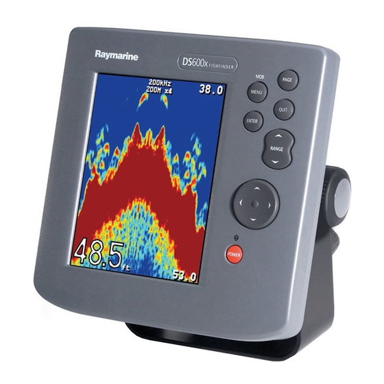
Figure 1-1: The DS600X employs a very high transmission repetition or “ping” rate which, along with the digital adaptive high sample rate receiver, ensures that fish and bottom structure are presented in superb detail and optimal color allocation. -
Page 12: Features
• Speedometer-style digital data screen overlay • NMEA 0183 compliant • Easy Bracket or Flush mounting • Waterproof to IPX7 Figure 1-2: Transducer Basic Fishfinder System using the DS600X DS600X Digital Fishfinder Fishfinder... -
Page 13: General
Chapter 1: Overview General The DS600X system, illustrated below, is comprised of the digital fishfinder, transducer and associated cables. The DS600X is waterproof to IPX7 and can be installed either above or below deck. The unit includes connections to: •... - Page 14 DS600X Digital Fishfinder...
-
Page 15: Chapter 2: Installation
Chapter 2: Installation 2.1 Introduction This chapter provides installation instructions for your DS600X. Note: If you wish to practice using the unit before installation, connect the power cable and use the simulator mode as described in Chapter 3. For pow- er, connect a 12VDC power supply, attaching the red wire to positive and the black wire to negative. -
Page 16: Selecting The Equipment Location
Bronze Thru-hull Transducer for DS400X/DS500X/DS600X (B744V) 2.3 Selecting the Equipment Location Mounting Location The DS600X is waterproof to IPX7 is and designed to be mounted either above or below deck. The unit should be protected from physical damage and excessive vibration. -
Page 17: Cable Runs
The power cable may be extended by up to 60 ft (20 m) using a wire gauge of AWG 12 or greater. The DS600X is intended for use on the boat’s DC power systems rated from 10-18 Volts DC (13.8V nominal). - Page 18 DS600X Digital Fishfinder 1.57 in (39.9 mm) 5.08 in (129 mm) 2.52 in (64 mm) 7.00 in (178 mm) 5.12 in (130 mm) plug clearance D6455-1 4.72 in (120 mm) 1.38 in 1.38 in (35 mm) (35 mm) Figure 2-1:...
-
Page 19: Mounting The Fishfinder
Chapter 2: Installation 2.5 Mounting the Fishfinder The DS600X can be mounted on a dash, chart table, bulkhead or deckhead using the supplied hardware. The unit can also be flush mounted directly into the console. Bracket Mounting ➤ To mount the DS600X on the supplied bracket: 1. - Page 20 8. Hand tighten the studs into the holes provided at the rear of the unit. 9. Place the gasket on the rear of the fishfinder. 10. Run the Power/NMEA cable and transducer cables through the back of the cutout and connect to the unit. Avoid tight bends in the cables.
-
Page 21: System Connections
Figure 2-3: DC Power and NMEA Connection The DS600X is intended for use on boat’s DC power systems rated from 10- 18 Volts DC (13.8V nominal). A 5 ft (1.5 m) cable is supplied for connecting the boat’s DC power and NMEA interface to the unit. - Page 22 Figure 2-5: CAUTION: If the power connections are accidentally reversed the system will not work. Use a multimeter to ensure that the input power leads are connected for correct polarity. Installing the Fuse DS600X Digital Fishfinder Color Black White Green Gray...
-
Page 23: Transducer Connection
If the cable is cut, it must be replaced—it cannot be repaired. Cutting the cable will also void the warranty. WARNING: Removing the transducer cable from the rear of the DS600X while the fishfinder is powered on can cause sparks. Only remove the transducer cable after power has been removed from the DS600X. - Page 24 DS600X Digital Fishfinder...
-
Page 25: Chapter 3: Getting Started
POWER on the connector panel. Press the POWER button on the DS600X. Details on setting up your DS600X and display are given in Chapter 6. 3.3 Simulator Mode If you have not fully installed the fishfinder, you can still operate in Simulator mode by connecting the fishfinder to a 12VDC power supply. -
Page 26: Lcd Display
Fishfinder Page, is displayed. This is a graphical representation of the echoes seen by the DS600X. As time passes, this display scrolls from right to left and becomes a record of the echoes seen. A typical display is shown in Figure 3- The images at the right hand side of the display are the most recent echoes. -
Page 27: Interpreting The Sounder Image
The DS600X uses sound waves to find fish and show bottom structure. The transducer sends sound waves into the water; these sound waves strike fish, the bottom, or other objects in the water and return as echoes. The DS600X interprets these echoes to present an image of the fish and bottom. -
Page 28: Target Indications
44. The size of the target The larger the target, the larger the return on the fishfinder display. The size of a fish target is however dependent upon the size of the fish’s swim bladder rather than its overall size. -
Page 29: Keypad Operation
Press again to display Navigation data: Lat/Lon, Speed Over Ground (SOG), Course Over Ground (COG), Waypoint location, Range and Bearing and Time of day. This information is only available if the fishfinder is connected via NMEA to another device outputting navigation data. -
Page 30: Using The Variable Range Marker (Vrm)
VRM’s position on the screen. POWER POWER Press to turn on the fishfinder. Press and hold for three seconds to turn unit off. Press and release as a shortcut to the DISPLAY SET UP... Brightness setting. 3.7 Using the Variable Range Marker (VRM) The VRM (Variable Range Marker) key is used to determine the distance behind the boat of an object on the display. -
Page 31: Selecting The Display Page
ENTER Figure 3-4: 3.8 Selecting the Display Page The DS600X Fishfinder provides you with three Display Pages for presenting information. • Fishfinder Page Displays sounder data. This is the default screen; it appears when you first power on the unit. - Page 32 Each key press advances the Page screen. Press 26°15:512 W 080°04:664 26°16:322 W 080°03:846 00 :16 1 . 25 4:01:38 10/12/2004 Figure 3-5: to return to Fishfinder Screen Press to display Nav Data Display Pages DS600X Digital Fishfinder Press to display Temp Screen Minutes D6634-1...
-
Page 33: Menu Operation
Chapter 3: Getting Started 3.9 Menu Operation DS600X Fishfinder Page functions can be accessed using the controls that are displayed when you press the MENU key. The Main Menu is displayed. These function control: • General Fishfinder Operations • Display Control Functions •... - Page 34 NAV. SET UP ALARMS SOUNDER SETUP UNITS NMEA-OUT SETUP Language Key Beep Key Help Depth Offset Speed Calibrate Temp Calibrate Sounder Simulator DS600X Digital Fishfinder Speed Selection Temperature Background Color Battery Trip Auto Scroll LAT/LONG Analog Gauges Waypoint RNG/BRG Bearing Mode...
-
Page 35: Chapter 4: Main Menu
Chapter 4: Main Menu Chapter 4: Main Menu 4.1 Introduction This chapter provides basic menu functions for using the DS600X Digital Fishfinder. More detailed information on using the Display controls and sounder setup is provided in Chapter 5 and Chapter 6, respectively. -
Page 36: Main Menu
4. To edit the highlighted menu item, press the trackpad < or > keys to scroll through the available options. Once the item is changed, the change is accepted; you need not use the ENTER key to select. MAIN MENU MAIN MENU GAIN MODE GAIN MODE DS600X Digital Fishfinder D6643-1 D6644-1... - Page 37 Chapter 4: Main Menu 5. For some numerical settings you will press the ENTER key to select and then use the trackpad to increment or decrement the value. For example, to change a manual setting: i. Use the trackpad to browse to MANUAL. ii.
- Page 38 Note: Menu items that are displayed in all caps followed by an ellipsis (GAIN MODE..., for example) contains sub-menus. Use the trackpad keys to scroll through the sub-menus. MAIN MENU MAIN MENU DS600X Digital Fishfinder ARROW and ENTER key-help symbols prompting you to use Trackpad and ENTER keys to change this menu item.
-
Page 39: Fishfinder Operation Controls
Chapter 4: Main Menu 4.2 Fishfinder Operation Controls The fishfinder operation menu items are outlined in Table 4-1 . Table 4-1: Fishfinder Menu Items Menu Scroll Speed Range Frequency A-Scope GAIN MODE... Sub-Menu Options — PAUSED — AUTOMATIC, MANUAL —... -
Page 40: Scroll Speed
Select MANUAL to enable the RANGE key for setting the range. • If you press the RANGE key to manually set the range while the automatic setting is enabled displays, the fishfinder displays the following message: Sub-Menu Options View... - Page 41 Chapter 4: Main Menu The range mode must be set to MANUAL before the range will change. Press UP, DOWN, or MENU. Pressing Range field in the MAIN MENU so you can make the change if desired. If you wish to remain in Automatic Range mode, press QUIT. The following range/shift values are available: Table 4-2: Range Values Feet...
-
Page 42: Frequency
Frequency The DS600X uses dual frequency sonar—50 kHz and 200 kHz—and can be used in either auto or manual modes. The DS600X can automatically select the appropriate frequency, based on the current display range. As the depth increases while in Auto Frequency mode, the fishfinder shifts from 200 kHz to 50 kHz. -
Page 43: A-Scope
Chapter 4: Main Menu A-Scope Use the A-Scope screen to show raw sonar data directly from the transducer beam. This gives you a “real time” image of fish and bottom structure directly below the transducer. This function is very useful in showing the strength of the echo returned from a fish. -
Page 44: Gain Mode
Note: Automatic Gain settings take advantage of the hardware’s advanced digital technology. As a result, the sounder typically performs better in auto- matic mode than manual. For better performance Raymarine recommends selecting AUTO mode for all Gain options. Note that this menu item is in all caps and in followed by an ellipsis (...). This is an indicator that the setting contains sub-menus. -
Page 45: Gain
The DS600X provides three pre-defined automatic gain settings: AUTO FISHING is the highest automatic gain setting. It gives the best •... -
Page 46: Time Variable Gain (Tvg)
Increasing the TVG value increases the maximum depth to which TVG is applied. Decreasing reduces the maximum depth. Although you can manually set the TVG level, Raymarine recommends letting the unit choose the proper level for you by selecting AUTOMATIC. -
Page 47: Second Echo Rejection
Chapter 4: Main Menu Second Echo Rejection A so-called “second echo” can caused by the sonar signal returning from the bottom, reflecting off the water’s surface, bouncing off the bottom again and returning. This option helps eliminate identifying a false bottom. Select from the following: OFF, which offers no rejection •... -
Page 48: View
FULL SCREEN zooms the entire screen. • Note: If also displaying dual frequencies, the zoomed image is displayed ful- ly in both frequency windows. Figure 4-3: Zoom with Split Screen DS600X Digital Fishfinder D6641-1... -
Page 49: Zoom X2, X3, X4 Magnification
Chapter 4: Main Menu Zoom x2, x3, x4 Magnification This parameter sets the level of display magnification. The greater the zoom, the smaller the area you are viewing, so the smaller the Zoom Range Bar. Select from: • • • Mode AUTOMATIC adjusts the position of the zoom window so that bottom •... - Page 50 DS600X Digital Fishfinder...
-
Page 51: Chapter 5: Display Set Up
5.1 Introduction This chapter will help you to become familiar with the functions of the display’s controls. A general discussion of the fishfinder’s menu items was provided in Chapter 4. Information on setting up the sounder is provided in Chapter 6. - Page 52 DS600X Digital Fishfinder MAIN MENU MAIN MENU MENU MAIN MENU MAIN MENU DISPLAY SET UP DISPLAY SET UP ENTER Figure 5-1: Accessing Display Set Up Menu Items...
- Page 53 Chapter 5: Display Set Up The Display Set Up menu items are listed in Table 5-1 and then described following that. Table 5-1: DISPLAY SET UP... Menu Menu Brightness Target Depth ID Depth Digit Size Transparent Menu PALETTE... DATA ITEMS... NAV.
-
Page 54: Brightness
Sub Menu Options OFF, Bearing Mode TRUE, MAGNETIC Time Offset UTC, –13 to +13 hours Time Format 12 HOUR, 24 HOUR Time OFF, ALARM CLOCK OFF, Date Format MM/DD/YY, DD/MM/YY Date OFF, DS600X Digital Fishfinder Default TRUE 12 HOUR MM/DD/YY... -
Page 55: Depth Digit Size
Chapter 5: Display Set Up 44.2 Figure 5-2: Depth Digit Size This setting controls the size of the digital depth readout at the lower left of the screen. Choose from the following: LARGE (default) • SMALL • Transparent Menu This option removes the background white from the menu dialog box, enabling you to see data that would normally be hidden. -
Page 56: Palette
Figure 5-3: PALETTE... The DS600X offers you six different display color combinations. You can select the color set, for a bold or soft color palette. The brightness of the screen can be adjusted over a wide range, suitable for viewing in daylight (high brightness level) or at night (low brightness level). -
Page 57: Analog Gauges
Chapter 5: Display Set Up Background Color When the CLASSIC palette is selected, you can also choose the background color used. Three colors are available for the sonar display background – black, white and blue. You will probably find that you need to change the background color in different light conditions. -
Page 58: Nav. Set Up
Note: When analog gauges are selected, the Navigation Items cannot be dis- played on the Fishfinder page. You must switch to the Nav Data page using the PAGE key to view that information. Figure 5-4: NAV. SET UP... (Navigation Data) Similar to Data Items, this is a list of navigation data you can display on the screen as separate data items. -
Page 59: Time Offset
• Display ON or OFF Note: When analog gauges are selected as Data Items, the Navigation Items cannot be displayed on the Fishfinder page. You must switch to the Nav Data page using the PAGE key to view this information. - Page 60 DS600X Digital Fishfinder D6903-1 Figure 5-5: Displaying Navigation Data...
-
Page 61: Chapter 6: Sounder Set Up
Chapter 6: Sounder Set Up 6.1 Introduction Once you have installed your DS600X and are familiar with its basic operation, you need to set it up so that it displays information according to your preferences. The SYSTEM SET UP option enables you to set up your system configuration and personal preferences. - Page 62 Figure 6-1: MAIN MENU MAIN MENU MENU MAIN MENU MAIN MENU SOUNDER SET UP SOUNDER SET UP ENTER Accessing Sounder Set Up Menu Items DS600X Digital Fishfinder...
- Page 63 Chapter 6: Sounder Set Up The following table lists the setup menus and their options and shows the factory default setting. Each parameter is described in the following subsections. Table 6-1: SOUNDER SET UP... Menu Items Menu Sub-Menu ALARMS... Fish Alarm Shallow Alarm Shallow Range Deep Alarm...
- Page 64 TRUE, MAGNETIC MM/DD/YY, DD/MM/YY 12 HOUR, 24 HOUR OFF, — ENGLISH (UK), ENGLISH (US), DANISH, FRENCH, GERMAN, DUTCH, ICELANDIC, ITALIAN, NOWEGIAN, PORTUGUESE, SPANISH, SWEDISH, FINNISH — — DS600X Digital Fishfinder Default KNOTS NAUTICAL MILES TRUE MM/DD/YY 12 HOUR ENGLISH (US)
-
Page 65: Alarms
Chapter 6: Sounder Set Up Menu Sub-Menu Depth Offset Speed Calibrate Temp Calibrate Sounder Simulator ALARMS... This menu group is used to set up alarms that are available to alert you of certain conditions. Each alarm can be toggled ON and OFF and you set the threshold at which the alarms are triggered, except for the fish and battery voltage alarms. -
Page 66: Fish Alarm
DS600X Digital Fishfinder 41 40 44.2 D6900-1 Figure 6-2: FISH & DEPTH Target Depth IDs Fish Alarm If this alarm is ON, the unit sounds a beeper whenever it finds a fish. The default setting is OFF. Shallow Alarm If this alarm is ON and the depth below the boat is less than the value set using the Shallow Range setting, the beeper sounds and moving arrow indicators point to the digital depth display. -
Page 67: Deep Alarm
Chapter 6: Sounder Set Up Deep Alarm If this alarm is ON and the depth below the boat is greater than the value set using the Deep Range setting, the beeper sounds and moving arrow indicators point to the digital depth display. You cannot set the deep alarm to be shallower than the shallow alarm. -
Page 68: Temp. Rng. High
4. Press the < or > trackpad key to decrement/increment the alarm time. 5. When the time at which you want the alarm to sound is displayed, press ENTER again. The word ON and the time are highlighted again. The alarm is set. -or- 71.9 DS600X Digital Fishfinder Indicator scrolling Indicator flashing... -
Page 69: Units
Chapter 6: Sounder Set Up 6. When the alarm clock sounds, it is accompanied by a message box labeled ALARM CLOCK displaying the time. The default setting is OFF. Figure 6-5: UNITS... You can set the units for each system parameter. The units you set will be used to display all data, including information received from other instruments on the system. -
Page 70: Bearing Mode
Bearing & Distance to Waypoint – Rhumb Line Depth Below Transducer Depth Geographic Position – Latitude/Longitude Water Temperature Water Speed and Heading Distance Travelled through the Water Course Over Ground and Ground Speed Time and Date Data repeated from external device DS600X Digital Fishfinder... -
Page 71: Language
Chapter 6: Sounder Set Up Language Select the language in which you wish information to be displayed. The selected language will be used for all screen text. Select from the following: ENGLISH (UK) • ENGLISH (US) (default) • DANISH • FRENCH •... -
Page 72: Depth Offset
This area is informational only; it is not editable. SW Version displays the software version of the DS600X. Serial Number displays the serial number of the DS600X, which should also be marked on the label on the rear of the unit. -
Page 73: Chapter 7: Maintenance And Problem Solving
Check that the cable connectors are firmly attached. Cleaning Instructions Cleaning the Unit The DS600X is a sealed unit and does not require regular cleaning. However, if you find it necessary to clean the unit, please follow these basic procedures: •... -
Page 74: Cleaning The Hull
To minimize these effects and enable you to get the best possible perfor- mance from your Raymarine equipment, guidelines are given in the installation instructions, to enable you to ensure minimum interaction between different items of equipment, i.e. -
Page 75: Problem Solving
Chapter 7: Maintenance and Problem Solving 7.2 Problem Solving All Raymarine products are, prior to packing and shipping, subjected to comprehensive test and quality assurance programs. However, if this unit should develop a fault, please refer to the following table to identify the most likely cause and the corrective action required to restore normal operation. -
Page 76: How To Contact Raymarine
Clicking the Find Answers link routes you to our solution database. Search questions and answers by product, category, keywords, or phrases. If the answer you are seeking is not available, click the Ask Raymarine tab to submit your own question to our technical support staff, who will reply to you by e-mail. -
Page 77: Technical Support
Technical Service is available Monday through Friday 4:00 AM to 6:00 PM Eastern Time. Please have the Raymarine item or part number ready when calling if placing an order. If you are not sure which item is appropriate for your unit, you... -
Page 78: Worldwide Support
Accessories and Parts Raymarine accessory items and parts are available through your authorized Raymarine dealer. Please refer to the lists of component part numbers and optional accessories in the Installation chapter of this manual and have the Raymarine part number ready when speaking with your dealer. -
Page 79: Appendix A: Specifications
Appendix A: Specifications Appendix A: Specifications General Size Weight Environmental Power Input Mounting Controls Display Display type Interface Connector Sounder Output Power: Frequency Pulse Length Max. Transmit Rate Depth Conforms to 89/336/EEC (EMC) H x W x D, excluding mounting bracket 6.93 x 7.0 x 2.52 in (176 x 178 x 64 mm) 1.87 lb (848 g) Waterproofing:... -
Page 80: Nmea Data
NMEA Data Connector POWER/NMEA DS600X Digital Fishfinder Received Transmitted BWC, BWR, GLL, ZDA, BWC, BWR, DBT, DPT, RMB, VTG, HDG, HDT GLL, MTW, VHW, VLW, VTG, ZDA... -
Page 81: Index
Index Accessories 5 Obtaining 66 Alarm Clock 49 Alarms 55 Alarm Clock 58 Deep Alarm 57 Deep Range 57 Fish Alarm 56 Shallow Alarm 56 Shallow Range 56 Target Depth ID 55 Temp Alarm 57 Temp Range 58 Analog Gauges 47 A-Scope 33 Auto Scroll 47 Background Color 47... - Page 82 Color Gain 35 Gain Mode 34 Int Rej 36 Max Ping Rate 37 Power 37 Second Echo Rejection 37 TVG 36 Help from Raymarine 66 Installation 5 Cables 7 EMC Guidelines 5 Location 6 Mounting 9 Int Rej 36 Key Beep 61...
- Page 83 Cable 11 Connection 11 POWER key 20 Power on 15 QUIT key 19 Range 30 Range and Bearing 49 RANGE key 20 Raymarine Addresses 67 Phone numbers 67 Website 66 Repair 67 RNG/BRG 49 Routine Checks 63 Safety EMC Guidelines 5...
- Page 84 Bearing Mode 60 Date Format 60 Depth Units 59 Distance Units 59 Speed Units 59 Temp Units 59 Time Format 60 VRM 19 Warranty iii DS600X Digital Fishfinder Waypoint 48 Website 66 Zoom 20 Magnification 39 Mode 39 View 38...
Need help?
Do you have a question about the DS600X and is the answer not in the manual?
Questions and answers